


VRB410

machine numbers | VRB210 | VRB410 | VRB420
operating guide / warranty
As an ENERGY STAR ® Partner, Zenith Electronics
Corporation has determined that this product
meets the ENERGY STA R® guidelines for energy
efficiency.
WARNING:
TO REDUCE THE RISK OF ELECTRIC SHOCK DO NOT REMOVE COVER (OR BACK). NO USER SERVICEABLE PARTS INSIDE.
REFER SERVICING TO QUALIFIED SERVICE PERSONNEL.
The lightning flash with arrowhead symbol, within an equilateral triangle, is intended to alert the user to the presence
of uninsulated “dangerous voltage” within the product’s enclosure that may be of sufficient magnitude to constitute a
risk of electric shock to persons.
The exclamation point within an equilateral triangle is intended to alert the user to the presence of important
operating and maintenance (servicing) instructions in the literature accompanying the appliance.
WARNING:
TO REDUCE THE RISK OF FIRE OR ELECTRIC SHOCK, DO NOT EXPOSE THIS APPLIANCE TO RAIN OR MOISTURE.
POWER CORD POLARIZATION:
CAUTION: To Prevent Electric Shock, match wide blade of plug to wide slot, fully insert.
ATTENTION: Pour éviter les chocs électriques, introduire la lame la plus large de la fiche dans la borne correspondante
de la prise et pousser jusqu’au fond.
NOTE TO CABLE/TV INSTALLER:
This reminder is provided to call the cable TV system installer’s attention to Article 820-40 of the National Electric Code
(U.S.A.). The code provides guidelines for proper grounding and, in particular, specifies that the cable ground shall be
connected to the grounding system of the building, as close to the point of the cable entry as practical.
REGULATORY INFORMATION:
This equipment has been tested and found to comply with the limits for a Class B digital device, pursuant to Part 15
of the FCC Rules. These limits are designed to provide reasonable protection against harmful interference when the
equipment is operated in a residential installation. This equipment generates, uses and can radiate radio frequency
energy and, if not installed and used in accordance with the instruction manual, may cause harmful interference to
radio communications. However, there is no guarantee that interference will not occur in a particular installation. If
this equipment does cause harmful interference to radio or television reception, which can be determined by turning
the equipment off and on, the user is encouraged to try to correct the interference by one or more of the following
measures:
• Reorient or relocate the receiving antenna.
• Increase the separation between the equipment and receiver.
• Connect the equipment into an outlet on a circuit different from that to which the receiver is
connected.
• Consult the dealer or an experienced radio/TV technician for help.
CAUTION:
Do not attempt to modify this product in any way without written authorization from Zenith Electronics
Corporation. Unauthorized modification could void the user’s authority to operate this product.
This class B digital apparatus meets all requirements of the Canadian Interference-Causing Equipment
Regulations.
“Ce appareil numérique de la class b respecte toutes les exigences du Règulement sur le matériel brouillier du
Canada.”
Zenith is a trademark of ZEC © Copyright Zenith Electronics Corporation 1999
RECORD YOUR MODEL NUMBER
(Now, while you can see it)
The model and serial number of your new VCR are located
on the back of the VCR cabinet. For your future convenience,
we suggest that you record these numbers here:
MODEL NO.____________________________________
SERIAL NO.____________________________________
WARNING
RISK OF ELECTRIC SHOCK
DO NOT OPEN
IMPORTANT SAFETY INSTRUCTIONS
SAFETY TIPS
PAGE 3
1. Read Instructions
Read all of the safety and operating instructions before
operating the product.
2. Retain Instructions
Keep all safety and operating instructions for future
reference.
3. Heed Warnings
Follow warnings on the product and in the operating
guide.
4. Follow Instructions
Follow all operating and use instructions.
5. Cleaning
Unplug this product from the wall outlet before
cleaning. Do not use liquid cleaners or aerosol cleaners.
Use a damp cloth for cleaning.
6. Attachments
Do not use attachments not recommended by product
manufacturer as they may cause hazards.
7. Water and Moisture
Do not use this product near water—for example, near
a bathtub, wash bowl, sink, or laundry tub, in a wet
basement, or near a swimming pool.
8. Accessories
Do not place product on an unstable cart, stand,
tripod, bracket, or table. Product may fall, causing
serious injury to a child or adult, and serious damage
to the product. Use only with a cart, stand, tripod,
bracket, or table recommended by the manufacturer or
sold with the product. Any mounting of product should
follow manufacturer’s instructions and should use a
mounting accessory recommended by manufacturer.
9. Transporting Product
Move product and cart combinations
with care. Quick stops, excessive
force, and uneven surfaces may cause
product and cart combination to
overturn.
10. Ventilation
Slots and openings in cabinet must not be blocked or
covered. They are provided for ventilation, to ensure
reliable operation, and to protect from overheating.
Never block openings by placing product on a bed,
sofa, rug, or other similar surface. Do not place product
in built-in installation such as a bookcase or rack
unless proper ventilation is provided or manufacturer’s
instructions have been adhered to.
11. Power Sources
Operate product only from type of power source
indicated on marking label. If you are not sure of the
type of power supply to your home, consult your
product dealer or local power company. For products
intended to operate from battery power or other
sources, refer to manual.
12. Line-Cord Polarization
Product is equipped with a polarized alternating-
current line plug (a plug having one blade wider than
the other). As a safety feature, this plug will fit into
power outlet only one way. If you’re unable to insert
plug fully into outlet, try reversing the plug. If plug
still fails to fit, contact an electrician to replace your
obsolete outlet. Do not defeat safety purpose of
polarized plug.
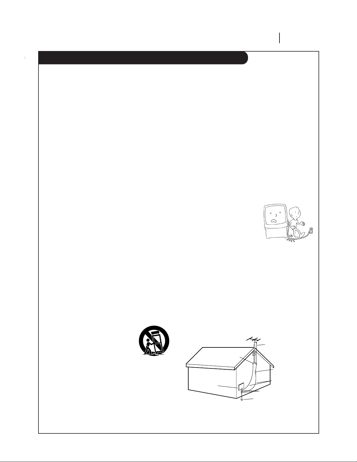
13. Power-Cord Protection
Route power-supply cords so
they are not likely to be
walked on or pinched by items
placed upon or against them,
paying particular attention to
cords at plugs, convenience
receptacles, and the point
where they exit from product.
14. Outdoor Antenna Grounding
If an outside antenna or cable system is connected to
this product, be sure antenna or cable system is
grounded so as to provide some protection against
voltage surges and built-up static charges. Article 810
of the National Electrical Code (USA), ANSI/NFPA 70
provides information on grounding of mast and
supporting structure, grounding of lead-in wire to an
antenna discharge unit connection to grounding
electrodes, and requirements for grounding electrode.
( See Fig. 1 below. )
These simple precautions will help ensure that you get many years of safe enjoyment from your new product.
Antenna Lead-in Wire
Antenna Discharge Unit
NEC Section 810-20
Grounding Conductors
NEC Section 810-21
Ground Clamps
Power Service Grounding
Electrode System
NEC Art 250, Part H
Ground
Clamp
Electric Service
Equipment
NEC: National Electrical Code
Antenna grounding per NEC Code, ANSI/NFPA 70
Fig. 1
IMPORTANT SAFETY INSTRUCTIONS
PAGE 4
SAFETY TIPS
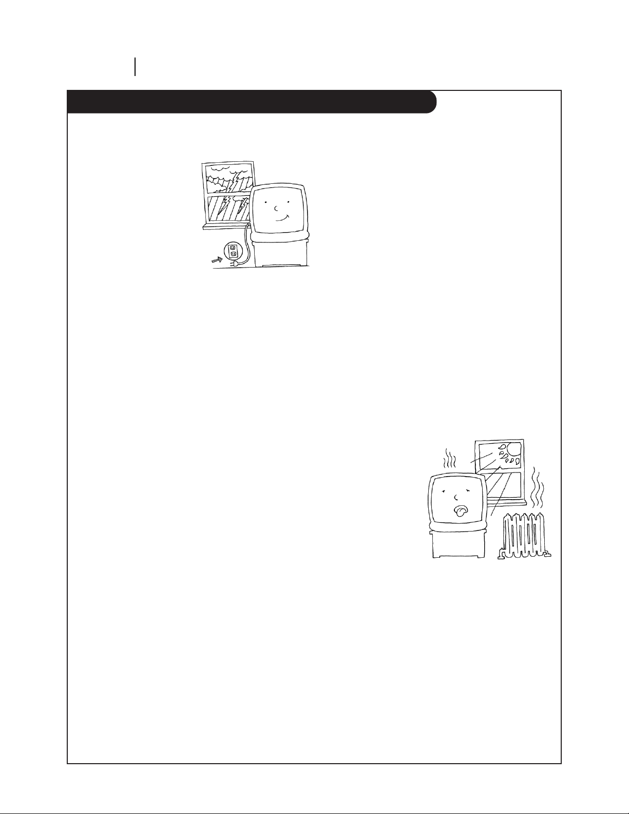
15. Lightning
For added protection for
this product during a
lightning storm, or when
product is left unattended
and unused for long
periods of time, unplug it
from the wall outlet and
disconnect antenna or
cable system. This will
prevent damage to product
due to lightning and
power line surges.
16. Power Lines
An outside antenna system should not be located in
the vicinity of overhead power lines or other electric
light or power circuits, or where it can fall into such
power lines or circuits. When installing an outside
antenna system, take extreme care to keep from
touching such power lines or circuits, as contact with
them might be fatal.
17. Overloading
Do not overload wall outlets, extension cords or
integral convenience receptacles, as this can result in
risk of fire or electric shock.
18. Object and Liquid Entry
Never push objects of any kind into this product
through openings, as they may touch dangerous
voltage points or short-out parts that could result in
fire or electric shock. Never spill liquid of any kind on
product.
19. Servicing
Do not attempt to service this product yourself, as
opening or removing covers may expose you to
dangerous voltage or other hazards. Refer all servicing
to qualified service personnel.
20. Wall or Ceiling Mounting
Mount product to wall or ceiling only as recommended
by manufacturer.
21. Replacement Parts
When replacement part(s) are required, be sure service
technician has used replacement part(s) specified by
manufacturer or have same characteristics as original
part(s). Unauthorized substitutions may result in fire,
electric shock, or other hazards.
22. Damage Requiring Service
Unplug this product from the wall outlet and refer
servicing to qualified service personnel under these
conditions:
a. If power-supply cord or plug is damaged.
b. If liquid has been spilled or objects have fallen into
product.
c. If product has been exposed to rain or water.
d. If product doesn’t operate normally by following
handbook instructions. Adjust only those controls
covered by handbook instructions; improper
adjustment of other controls may result in damage
and often requires extensive work by a qualified
technician to restore product to normal operation.
e. If product has been dropped or cabinet has been
damaged.
f. If product exhibits a distinct change in performance.
23. Heat
Keep product away
from heat sources
such as radiators,
heat registers, stoves,
or other products
(including amplifiers)
that produce heat.
24. Safety Check
Upon completion of any service or repairs to this
product, ask service technician to perform safety
checks to determine that product is in proper operating
condition.
These simple precautions will help ensure that you get many years of safe enjoyment from your new product.

Contents/Index
INSTALLATION PAGE 5
CONTENTS
SAFETY TIPS. . . . . . . . . . . . . . . . . . . . . . . . . . . . . 2-4
INSTALLATION . . . . . . . . . . . . . . . . . . . . . . . . . . 6-12
VCR Features Chart. . . . . . . . . . . . . . . . . . . . . . . . 6
Connections for Your VCR . . . . . . . . . . . . . . . . . . 7-8
Before you operate your VCR . . . . . . . . . . . . . . . 9-12
CONTROLS AND DISPLAYS. . . . . . . . . . . . . . . . . . 13-14
Front Panel Diagram . . . . . . . . . . . . . . . . . . . . . . 13
VCR Status Displays . . . . . . . . . . . . . . . . . . . . . . 14
OPERATION . . . . . . . . . . . . . . . . . . . . . . . . . . . 15-27
The Buttons on Your Remote . . . . . . . . . . . . . . . . 15
Clock Menu . . . . . . . . . . . . . . . . . . . . . . . . . . . . 16
Timer Menu. . . . . . . . . . . . . . . . . . . . . . . . . . . . 17
Setup Menu . . . . . . . . . . . . . . . . . . . . . . . . . . . 18
Audio Menu . . . . . . . . . . . . . . . . . . . . . . . . . . . 19
Watching TV Through the VCR . . . . . . . . . . . . . . . . 20
Camcorder Connected to VCR . . . . . . . . . . . . . . . . 21
Playing Tapes . . . . . . . . . . . . . . . . . . . . . . . . 22-23
Instant Recording . . . . . . . . . . . . . . . . . . . . . 24-26
Recording While You’re Away . . . . . . . . . . . . . . . . 27
TROUBLESHOOTING . . . . . . . . . . . . . . . . . . . . . . 28-30
SPECIFICATIONS. . . . . . . . . . . . . . . . . . . . . . . . . . . 31
INDEX
Audio Menu . . . . . . . . . . . . . . . . . . . . . . . . . . . . . .19
Auto Channel Search . . . . . . . . . . . . . . . . . . . . . .11, 18
Connections . . . . . . . . . . . . . . . . . . . . . . . . . . .7-8, 21
Channel Add/Del . . . . . . . . . . . . . . . . . . . . . . . .11, 18
Clock Set . . . . . . . . . . . . . . . . . . . . . . . . . . . . .11, 16
Features Chart . . . . . . . . . . . . . . . . . . . . . . . . . . . . .6
Front Panel Diagram . . . . . . . . . . . . . . . . . . . . . . . .13
Instant Recording . . . . . . . . . . . . . . . . . . . . . . . .24-26
Language Menu . . . . . . . . . . . . . . . . . . . . . . . . . . . .18
Main Menus . . . . . . . . . . . . . . . . . . . . . . . . . . . . . . .9
Playing Tapes . . . . . . . . . . . . . . . . . . . . . . . . . . .22-23
Remote Control . . . . . . . . . . . . . . . . . . . . . . . . . . . .15
Safety Information . . . . . . . . . . . . . . . . . . . . . . . . .2-4
Setup Menu . . . . . . . . . . . . . . . . . . . . . . . . . . . . . .18
SpeakEZ Function . . . . . . . . . . . . . . . . . . . . . . . . . .10
Timer Menu . . . . . . . . . . . . . . . . . . . . . . . . . . . . . .17
Timer-Controlled Recording . . . . . . . . . . . . . . . . . . . .27
Troubleshooting . . . . . . . . . . . . . . . . . . . . . . . . .28-30
VCR Status Displays . . . . . . . . . . . . . . . . . . . . . . . . .14
Warranty . . . . . . . . . . . . . . . . . . . . . . . . . . . . . . . .36
Watching TV through the VCR . . . . . . . . . . . . . . . . . .20

PAGE 6 INSTALLATION
VCR Features Chart
This page shows the features of your VCR and the differences between the models.
FEATURES VRB210 VRB410 VRB420
SpeakEZ Function X X X
2-Heads X N/A N/A
4-Heads (Special Video Effects) N/A X X
Full Load/Quick Start X X X
Auto Head Cleaner X X X
Audio System Monaural Monaural MTS Hi-Fi Stereo
Audio/Video (A/V) Jacks Monaural Monaural Stereo
Remote Control SC411Z X X X
Auto/Manual Band Select X X X
Auto/Manual Channel Search X X X
Channel Capability (CATV & TV) 181 181 181
Record Speeds SP/EP X X X
Playback Speeds SP/LP/EP X X X
Auto Playback System X X X
Auto/Manual Digital Tracking X X X
Instant Recording X X X
Timer-Controlled Recording X X X
Auto Playback Tape Speed Adjust X X X
Forward/Reverse Slow-Motion
N/A
XX
Video (4-head VCR) Variable 1/10 to 1/32 Variable 1/10 to 1/32
Pause/Still Video Noise Clear Clear
Real-Time Tape Counter X X X
Speed Search X X X
CM Skip X X X
English/Spanish/French Menus X X X
1-Year, 8-Event Timer X X X
LED Front Panel Indicator X X X
Auto Daylight Savings Time X X X
Hook-up Cable (VCR to TV) X X X
Energy Saving X X X
1. Model VRB420 is used for the description, operation, and details provided in this operating guide.
2. VCR design and specifications are subject to change without prior notice.
X = Feature is provided N/A = Feature is Not Available
INSTALLATION PAGE 7
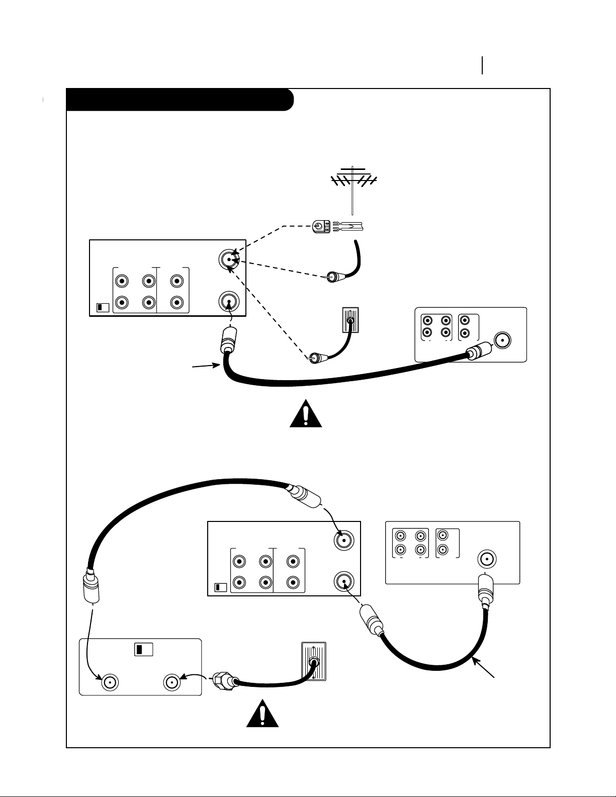
Connections for your VCR
Required connections for your VCR.
Connections With a Cable Box
Connections Without a Cable Box
Back Panel of Stereo VCR
Back Panel of Typical TV
Antenna
Flat Wire
(300 ohm)
300/75 ohm
Adaptor
(Not provided)
Cable TV
Wall Jack
This cable is provided
with your VCR.
OR
OR
IN
OUT OUT
IN
R
L
AUDIO
VIDEO
VHF/UHF/CATV
ANT
IN
ANT
IN
OUT
TO
TV
VHF/UHF/CATV
VIDEOR-AUDIO-L
OUT
IN
OUT
CH3 CH4
IN
Turn off power or unplug VCR
before making any connections.
Back Panel of
Typical Cable Box
CH3 CH4
CABLE
OUT IN
Back Panel of Stereo VCR Back Panel of Typical TV
IN IN
OUTOUT
R
L
AUDIO VIDEO
VHF/UHF/CATV
ANT
IN
Cable TV
Wall Jack
This cable is provided
with your VCR.
ANT
IN
OUT
TO
TV
VHF/UHF/CATV
VIDEOR-AUDIO-L
OUT
IN
OUT
CH3 CH4
IN
Turn off power or unplug VCR
before making any connections.
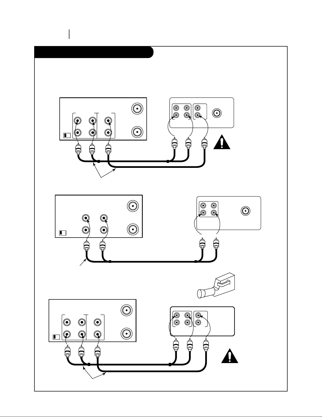
Connections for your VCR
PAGE 8 INSTALLATION
Optional connections for your VCR.
Audio/Video (A/V) Connections to TV
Use A/V connections for a better picture.
Accessory Audio/Video (A/V) Connections to VCR
CH3 CH4
OUT
IN
OUT
IN
R-AUDIO-L VIDEO
VHF/UHF/CATV
ANT
IN
Back Panel of Typical TV
ANT
IN
A/V cable is not provided with VCR.
ANT
IN
OUT
TO
TV
VHF/UHF/CATV
VIDEOAUDIO
OUT
IN
Back Panel of Monaural VCR
Back Panel of Stereo VCR
OUT
AUDIO VIDEO
IN
VHF/UHF/CATV
A/V cable is not provided with VCR.
ANT
IN
OUT
TO
TV
VHF/UHF/CATV
VIDEOR-AUDIO-L
OUT
IN
OUT
CH3 CH4
IN
Back Panel of Typical Monaural TV
Note: If the back panel
on your TV is different,
refer to the TV’s operating
guide.
ANT
IN
OUT
TO
TV
VHF/UHF/CATV
VIDEOR-AUDIO-L
OUT
IN
OUT
CH3 CH4
IN
Back Panel of Stereo VCR
OUT
IN
OUT
IN
R-AUDIO-L VIDEO
Jack panel of Accessory
A/V cable is not provided with VCR.
Turn off power
or unplug VCR
before making
any connections.
Turn off power
or unplug VCR
before making
any connections.
Accessory
Component:
Another VCR,
Camcorder,
Video Camera,
Satellite Receiver,
Laser Disc Player

INSTALLATION PAGE 9
Before you operate your VCR
Things you must do before you can operate your VCR.
Press number keys
QUIT = exit
SpeakEZ
CLOCK : 1
TIMER : 2
SETUP : 3
AUDIO : 4
PROGRAM 1
MONTH :
DAY :
START :
STOP :
CHANNEL :
SPEED :
REPEAT:
(1-8) to select program
ENTER to adjust program
Press number keys
QUIT = exit
SETUP MENU
AUTO PROGRAM: 1
CH. ADD/DEL: 2
SOURCE: 3
ON-SCREEN DISPLAY: 4
LANGUAGE SELECT: 5
CLOCK
MAIN MENU
TIMER SETUP AUDIO
Press NUMBER (1, 2, 3, 4) button
CLOCK MENU
AUTO DAYLIGHT SAVING:ON
1 ON 2 OFF
MANUAL CLOCK SET: 3
Press number keys
QUIT = exit
Press number keys
then ENTER QUIT = exit
AUDIO MENU
SpeakEZ: ON 1 ON 2 OFF
PLAYBACK: HI-FI
RECORD: STEREO
How to Access Menus
Menu operation is easy—just follow the instructions shown
at the bottom of the menu.
1. Press MENU to see main menu.
2. Press NUMBER (1, 2, 3, or 4) to see desired sub menu to
be used.
3. Press NUMBER to choose desired option to be changed.
4. Press QUIT to exit menu, or wait a few minutes and the
VCR returns to normal operation.
Note:
Perform menu operations with the VCR and TV on, and tune
the TV to channel 3 or 4. The VCR must also be in the VCR
mode of operation. Press the TV/VCR button repeatedly
until VCR indicator light appears in the front panel.
power
eject
ch
ch
menu
quit
sp/ep
enter
memory
rec/itr
123
456
789
tv/vcr
trk
0
cm skip
p
a
u
s
e
s
t
o
p
play
rew f fwd
Point remote toward VCR
Note:
Audio menu’s PLAYBACK and
RECORD options are available only
with stereo VCRs.
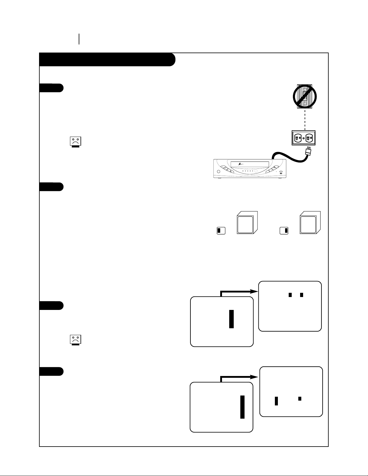
Before you operate your VCR
PAGE 10 INSTALLATION
Things you must do before you can operate your VCR.
Connect the Power
(Required) Plug your VCR into an unswitched
120 Vac, 60 Hz household power outlet. Turn on
the VCR by pressing the POWER on the remote
or on the VCR’s front panel. While plugged into
an AC outlet, the VCR consumes 3W of electrical
power in OFF condition.
Do not plug the VCR into a switched power
outlet. Otherwise, when the power is
switched off, the VCR turns off. You may
then have to reset the time and date, and
reprogram operational features.
Set Position of the CH3/CH4 Switch
(Required) The CH3/CH4 switch on the VCR’s
back panel determines which channel the VCR
uses to send video signals to your TV. The TV
must be tuned to the same channel you set with
the CH3/CH4 switch to see tape playback and
status displays from the VCR. To determine
which video channel provides the best picture
for your system, try the switch in CH3 position
and tune your TV to channel 3; then try the CH4
position and tune your TV to channel 4.
For a test display, press the TV/VCR button on
remote repeatedly until the VCR indicator light
appears in the VCR’s front panel display. Press
MENU on the remote to see the main menu.
Select SpeakEZ Function (On/Off)
A voice tells you how to use the features in the
menus if SpeakEZ is ON. (ON is recommended.).
See the AUDIO Menu for details.
SpeakEZ only functions with
ENGLISH.
Select Language for VCR Menus/Displays
(Optional) Select English, Spanish, or French
for VCR menus and status displays. See the
LANGUAGE SELECT option on the SETUP menu for
details.
Press number keys
QUIT = exit
SETUP MENU
AUTO PROGRAM: 1
CH. ADD/DEL: 2
SOURCE: 3
ON-SCREEN DISPLAY: 4
LANGUAGE SELECT: 5
Press number keys
then ENTER QUIT = exit
SETUP MENU
LANGUAGE SELECT : ENGLISH
1 ENGLISH 2 ESPAÑOL
3 FRANÇAIS
SETUP MENU
Press NUMBER (1, 2, or 3)
to select the desired
language
Press 5.
3
4
1
2
TYPICAL ZENITH VCR
WALL
SWITCH
POWER
OUTLET
Tune
TV to
Ch.3
CH3 CH4
Tune
TV to
Ch.4
CH3 CH4
OR
power
play
rew
f fwd
pause
power cst.in vcr rec timer
ch
rec/itr
sp/ep
ch
stop/eject
zenith
SpeakEZ
CLOCK : 1
TIMER : 2
SETUP : 3
AUDIO : 4
Press number keys
QUIT = exit
Press number keys
then ENTER QUIT = exit
AUDIO MENU
SpeakEZ: ON 1 ON 2 OFF
PLAYBACK: HI-FI
RECORD: STEREO
MAIN MENU
Press NUMBER (1 or 2) to
choose ON or OFF
Press 4.
INSTALLATION PAGE 11
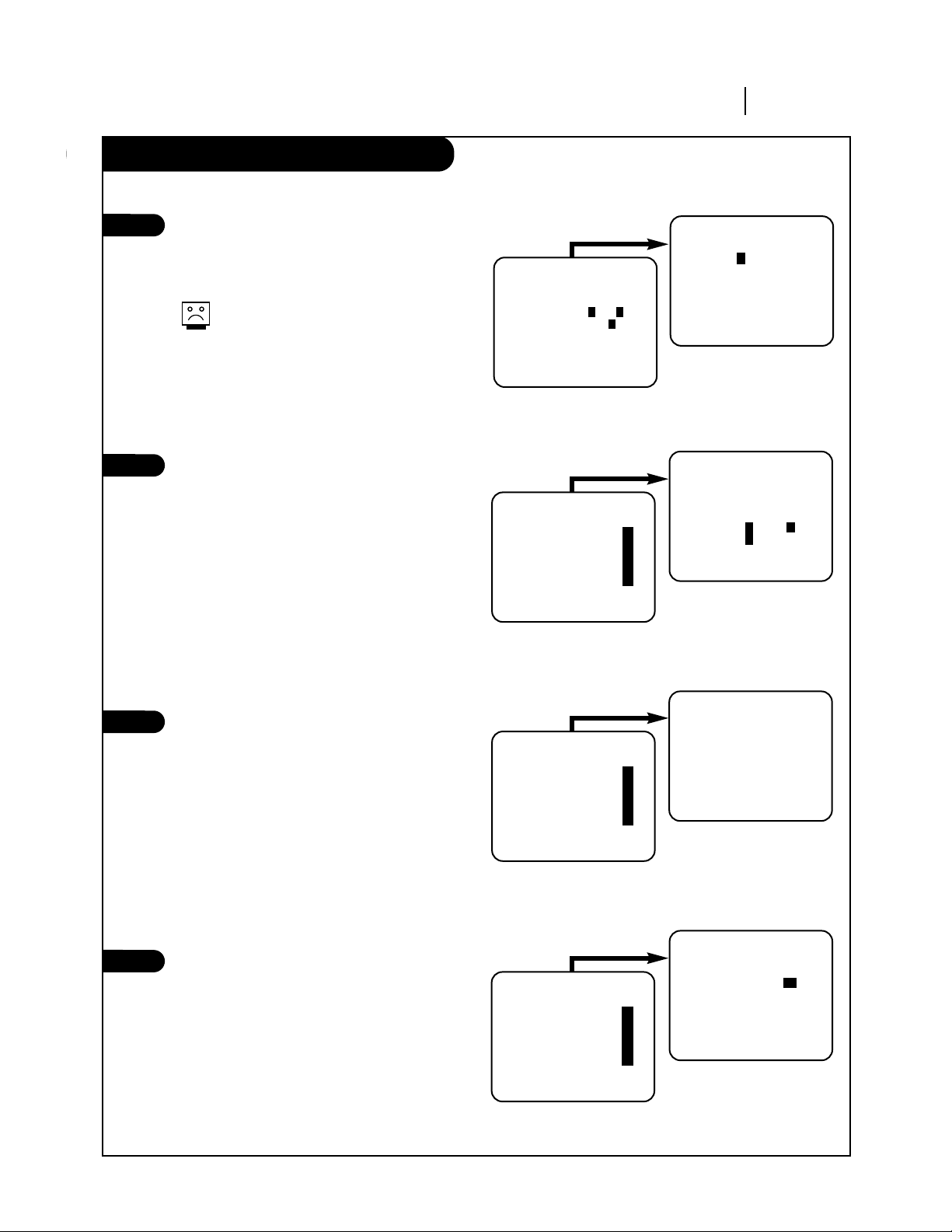
Before you operate your VCR
Some things you must do and others you may want to do before you can operate your VCR.
Set Date and Time for Clock
(Required) Set the clock in the VCR to the
current date and time. See CLOCK Menu on page
16 for details.
You must set the clock before you can use
any Timer-controlled VCR features, e.g.
TIMER recordings.
Select Source for VCR
(Optional) Set the source of the VCR for the
type of program signal you have connected to
the ANT IN jack on the back of the VCR. Choose
TV if you have an antenna connected to the VCR.
Choose CATV if you have a cable system (with or
without a cable box) connected to the VCR.
Choose AUX if you have an accessory
Audio/Video (A/V) connected to the VCR. See
SOURCE option on SETUP menu (page 18) for
details.
Use Auto Program to Find Channels
(Required) Use AUTO PROGRAM to find active
channels in your broadcast area. AUTO PROGRAM
stores the active channels that you can access
by using the CH (▼/▲). See AUTO PROGRAM on
the SETUP Menu (page 18) for details.
Use CH. ADD/DEL to Create Favorite
Channels
(Optional) Use CH. ADD/DEL to change the list
of active channels found when using AUTO
PROGRAM, so you can list your favorites. See
CH. ADD/DEL on the SETUP Menu (page 18) for
details.
7
8
6
Press number keys
QUIT = exit
SETUP MENU
AUTO PROGRAM: 1
CH. ADD/DEL: 2
SOURCE: 3
ON-SCREEN DISPLAY: 4
LANGUAGE SELECT: 5
Press number keys
then ENTER QUIT = exit
SETUP MENU
SOURCE: TUNER (TV)
1 TV 2 CATV
3 AUX
SETUP MENU
Press NUMBER (1, 2, or 3)
to select the desired
source
Press 3.
Press number keys
QUIT = exit
SETUP MENU
AUTO PROGRAM: 1
CH. ADD/DEL: 2
SOURCE: 3
ON-SCREEN DISPLAY: 4
LANGUAGE SELECT: 5
QUIT = exit
SETUP MENU
AUTO PROGRAM: SEARCHING
SETUP MENU
Press 1.
Press number keys
QUIT = exit
SETUP MENU
AUTO PROGRAM: 1
CH. ADD/DEL: 2
SOURCE: 3
ON-SCREEN DISPLAY: 4
LANGUAGE SELECT: 5
Press number keys
then ENTER QUIT = exit
SETUP MENU
CH. ADD/DEL: CH. 2 ADD
SETUP MENU
Press NUMBER (0-9)
then ENTER
Press 2.
CLOCK MENU
AUTO DAYLIGHT SAVING:ON
1 ON 2 OFF
MANUAL CLOCK SET: 3
Press number keys
QUIT = exit
CLOCK MENU
MONTH : 1 JANUARY
DAY : 1 FRI
YEAR : 1999
TIME : 12:00 AM
Press number keys
then ENTER QUIT = exit
CLOCK MENU
Press NUMBER (0-9) then
ENTER to set date and time
Press 3.
5
 Loading...