


Zenith A32B84R, A27B41, A36B41W, A36B41D, A32B41D OPERATING GUIDE
...machine numbers |
A27B41 |
A32B41 |
A32B84 |
A36B41 |
Thanks for choosing Zenith!
h o o k u p d i r e c t o r y
p a g e 3
y o u r o n - s c r e e n m e n u s |
16 |
p a g e |
i n d e x
p a g e 47
o p e r a t i n g g u i d e / w a r r a n t y
RECORD YOUR MODEL NUMBER (Now, while you can see it)
The model and serial number of your new TV are located on the back of the TV cabinet. For your future convenience, we suggest that your record these numbers here:
MODEL NO.____________________________________
SERIAL NO.____________________________________
WARNING
RISK OF ELECTRIC SHOCK
DO NOT OPEN
WARNING:
TO REDUCE THE RISK OF ELECTRIC SHOCK DO NOT REMOVE COVER (OR BACK). NO USER SERVICEABLE PARTS INSIDE. REFER SERVICING TO QUALIFIED SERVICE PERSONNEL.
The lightning flash with arrowhead symbol, within an equilateral triangle, is intended to alert the user to the presence of uninsulated “dangerous voltage” within the product’s enclosure that may be of sufficient magnitude to constitute a risk of electric shock to persons.
The exclamation point within an equilateral triangle is intended to alert the user to the presence of important operating and maintenance (servicing) instructions in the literature accompanying the appliance.
WARNING:
TO PREVENT FIRE OR SHOCK HAZARDS, DO NOT EXPOSE THIS PRODUCT TO RAIN OR MOISTURE.
POWER CORD POLARIZATION:
CAUTION: To Prevent Electric Shock, Match wide blade of plug to wide slot, fully insert.
ATTENTION: Pour éviter les chocs électriques, introduire la lame la plus large de la fiche dans la borne correspondante de la prise et pousser jusqu’au fond.
NOTE TO CABLE/TV INSTALLER:
This reminder is provided to call the cable TV system installer’s attention to Article 820-40 of the National Electric Code (U.S.A.). The code provides guidelines for proper grounding and, in particular, specifies that the cable ground shall be connected to the grounding system of the building, as close to the point of the cable entry as practical.
REGULATORY INFORMATION:
This equipment has been tested and found to comply with the limits for a Class B digital device, pursuant to Part 15 of the FCC Rules. These limits are designed to provide reasonable protection against harmful interference when the equipment is operated in a residential installation. This equipment generates, uses and can radiate radio frequency
energy and, if not installed and used in accordance with the instruction manual, may cause harmful interference to radio communications. However, there is no guarantee that interference will not occur in a particular installation. If this equipment does cause harmful interference to radio or television reception, which can be determined by turning
the equipment off and on, the user is encouraged to try to correct the interference by one or more of the following measures: • Reorient or relocate the receiving antenna.
•Increase the separation between the equipment and receiver.
•Connect the equipment into an outlet on a circuit different from that to which the receiver is connected.
•Consult the dealer or an experienced radio/TV technician for help.
CAUTION:
Do not attempt to modify this product in any way without written authorization from Zenith Electronics Corporation. Unauthorized modification could void the user’s authority to operate this product.

INSTALLATION |
GETTING STARTED |
P A G E 3 |
|
|
|
Hook-Up Directory
IMPORTANT!!
Use this page to decide where you need to begin your setup. First, find the line below that best describes what you want to do, then go to that page number. Note: Design and specifications are subject to change without prior notification.
If you are using an antenna and no other equipment, go to . . . . . . . . . . . . . . . . . . page 4
If you have cable and no other equipment, go to . . . . . . . . . . . . . . . . . . . . . . . . . page 5
Cable TV wall jack
In |
Cable box |
Out 
Antenna with VCR |
If you are using an antenna and have a VCR, go to . . . . . . . . . . . . . . . . . . . . . . . |
page 6 |
This page will direct you to which page to go to for proper hookup of your Entertainment Machine.
Cable and VCR |
If you have cable and a VCR, go to . . . . . . . . . . . . . . . . . . . . . . . . . . . . . . . . . . |
page 7 |
Cable TV |
|
|
wall jack |
|
|
In |
Cable box |
|
Out |
|
|
Other |
If you have a Super VHS VCR, a DVD Player, or Audio equipment, go to . . . . . . . . . . . |
pages 8-9 |
3374-O
P A G E 4 |
INSTALLATION |
STANDARD |
|
|
|
Connect an
antenna
to your
Entertainment
Machine.
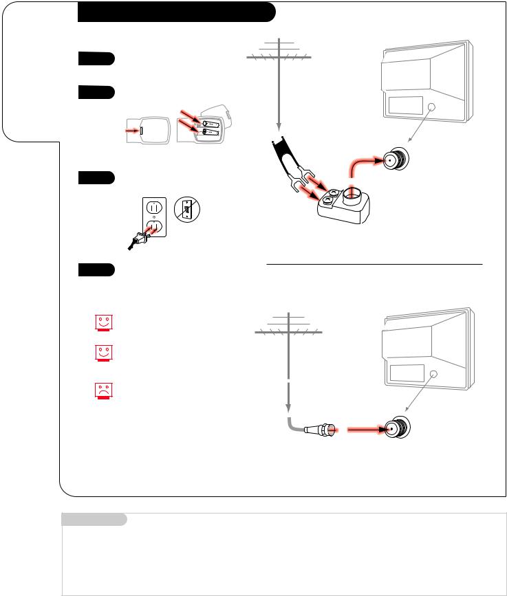
Hook Up Your Antenna to the TV |
|
|
|
1 |
Hook up your Entertainment |
|
|
|
Machine, see diagrams at right. |
Antenna |
TV back |
|
|
|
|
2 |
Remove the back of the remote |
|
|
and put in two AAA batteries. |
|
|
|
3
4
back of remote
Plug in your TV. Do not plug it into a switched outlet.
Go to page 10 to Auto Program your Entertainment Machine.
Flat wire |
TV back panel |
|
(300 ohm) |
||
(expanded view) |
||
|
Antenna
/ Cable
300/75 ohm Adapter
If you have a 75 ohm RF cable, then you don’t need any adapters!
Remember, when screwing RF cables onto jacks, clockwise tightens, and counterclockwise loosens.
TV back
Antenna
A 300 to 75 ohm adapter is not |
|
included with your Zenith |
TV back panel |
Entertainment Machine. |
(expanded view) |
|
RF coaxial wire |
|
(75ohm) |
|
Antenna |
|
/ Cable |
Mini glossary
75 OHM RF CABLE |
The wire that comes from an off-air antenna or cable service provider. Each end looks like a hex shaped nut with a wire |
|
sticking through the middle, and it screws onto the threaded jack on the back of your TV. |
300 TO 75 OHM ADAPTER |
A small device that connects a two-wire 300 ohm antenna to a 75 ohm RF jack. They are usually about an |
|
inch long with two screws on one end and a round opening with a wire sticking out on the other end. |
3374-O
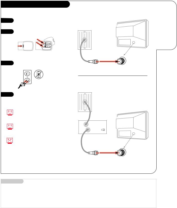
Hook Up Your Cable (CATV) to the TV
1 |
Hook up your Entertainment |
|
Machine, see diagrams at right. |
2 |
Remove the back of the remote |
|
and put in two AAA batteries. |
||
|
||
|
back of |
|
|
remote |
3 |
Plug in your TV. Do not plug it |
|
into a switched outlet. |
||
|
4 |
Go to page 10 to Auto Program |
|
your Entertainment Machine. |
||
|
If you’re using a cable box, leave your TV on channel 3 or 4 and use your cable box to change channels.
Remember, when screwing RF cables onto jacks, clockwise tightens, and counterclockwise loosens.
If you’re using a cable box, AutoProgram (page 10) might only find the channel your cable service is on (usually channel 3 or 4). Don’t worry, that’s all you need!
INSTALLATION |
STANDARD |
P A G E 5 |
|
|
|
Connect cable to your
Without Cable Box Entertainment
Machine.
Cable TV wall jack
TV back
TV back panel (expanded view)
RF coaxial wire (75ohm)
Antenna
/ Cable
With Cable Box
Cable TV wall jack
In |
|
TV back |
Cable box |
||
Out |
output |
3 4 |
|
switch |
|
TV back panel
(expanded view)
RF coaxial wire (75ohm)
Antenna
/ Cable
Mini glossary
CABLE SERVICE The wire that supplies all your cable TV (CATV) stations.
3374-O

P A G E 6 |
INSTALLATION |
STANDARD |
|
|
|
Connect your off-air antenna and VCR to your Entertainment Machine.
Hook Up Antenna and VCR to the TV
1 |
Hook up your Entertainment |
|
Machine, see diagrams at right. |
(VCR with Flat Wire Antenna Adapter)
Antenna |
Flat wire |
VCR back |
(300 ohm) |
|
2
3
4
Remove the back of the remote and put in two AAA batteries.
back of remote
Plug in your TV. Do not plug it into a switched outlet.
Go to page 10 to Auto Program your Entertainment Machine.
VCR back AV panel
300/75 ohm |
In |
output |
3 4 |
Adapter |
|
switch |
|
|
Audio |
Video |
|
|
Out |
||
|
R-L Out |
Out |
|
TV back |
|
|
|
|
RF coaxial wire |
|
|
|
(75ohm) |
|
|
|
not included |
|
|
|
with TV |
|
|
A/V cables not included with TV
TV back panel (expanded view)
Remember, when screwing
RF cables onto jacks, clockwise tightens, and counterclockwise loosens.
Use Video sources for better picture and sound.
Without A/V cables, VCRs will not play videocassettes in stereo sound.
(VCR with Round Antenna Wire)
|
VCR back |
|
|
Antenna |
|
|
|
VCR back AV panel |
|||
Round wire (75ohm) |
output |
|
|
In |
|
||
|
switch 3 4 |
||
Out |
Audio |
Video |
|
R-L Out |
Out |
||
|
|||
TV back |
|
|
|
RF coaxial wire |
|
|
|
(75ohm) |
|
|
|
not included |
|
|
|
with TV |
|
|
|
A/V cables not included with TV
TV back panel (expanded view)
3374-O
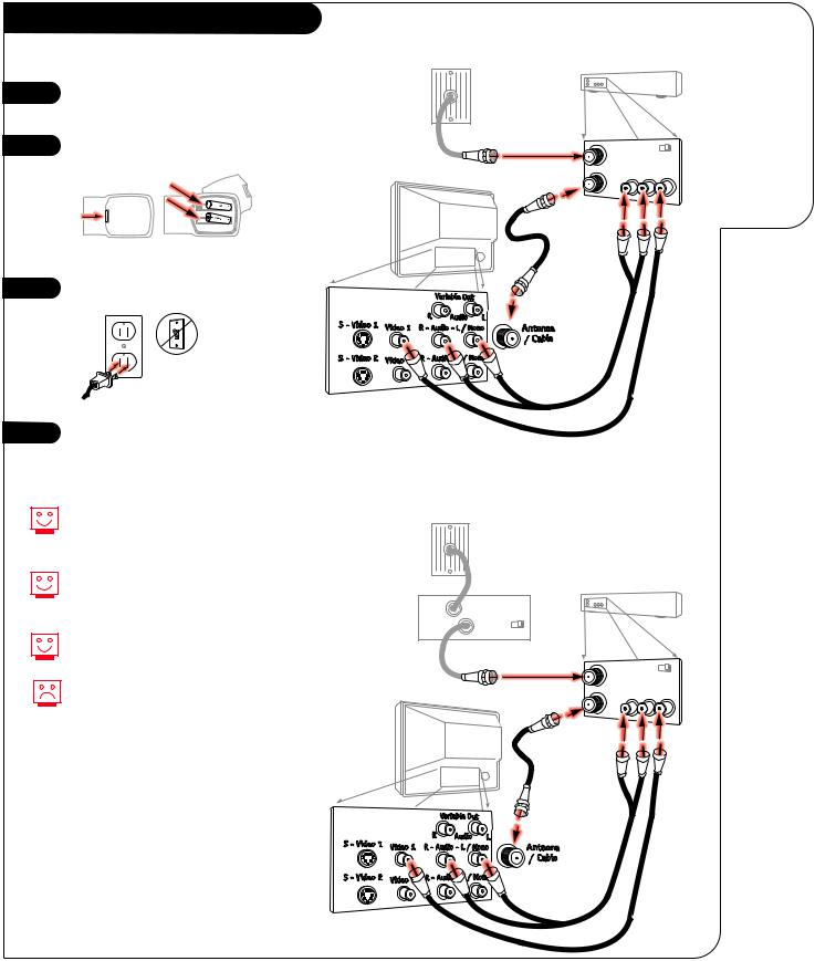
Hook Up Your Cable (CATV) and VCR
1 |
Hook up your Entertainment |
|
Machine, see diagrams at right. |
2 |
Remove the back of the remote |
|
and put in two AAA batteries. |
||
|
||
|
back of |
|
|
remote |
|
3 |
Plug in your TV. Do not plug it |
|
into a switched outlet. |
||
|
4 |
Go to page 10 to Auto Program |
|
your Entertainment Machine. |
||
|
Leave your VCR and your television tuned to channel three and use the cable box to change channels.
Remember, when screwing in RF cables onto jacks, clockwise tightens, and counterclockwise loosens.
Use Video sources for better picture and sound.
No A/V cables are included with your Zenith Entertainment Machine. Without A/V cables, VCRs will not play videocassettes in stereo sound.
INSTALLATION |
STANDARD |
P A G E 7 |
|
|
|
Without Cable Box |
|
Connect |
|
|
|
Cable TV |
|
your VCR and |
wall jack |
|
Cable to your |
|
|
|
|
VCR back |
Entertainment |
|
|
Machine. |
VCR back AV panel |
||
Round wire (75ohm) |
output |
|
In |
|
|
|
switch 3 4 |
|
Out |
Audio |
Video |
R-L Out |
Out |
|
TV back |
|
|
RF coaxial wire |
|
|
(75ohm) |
|
|
not included |
|
|
with TV |
|
|
A/V cables not included with TV
TV back panel (expanded view)
With Cable Box
Cable TV wall jack
In |
Cable box |
|
VCR back |
|
|
|
|
||
Out |
output |
|
|
|
switch 3 4 |
|
|
|
|
|
|
|
|
|
|
Round wire (75ohm) |
VCR back AV panel |
||
|
In |
output |
|
|
|
|
|
||
|
|
switch 3 4 |
||
|
|
|
||
|
|
|
Audio |
Video |
|
|
Out R-L Out |
Out |
|
|
TV back |
|
|
|
|
|
RF coaxial wire |
|
|
|
|
(75ohm) |
|
|
|
|
not included |
|
|
|
|
with TV |
|
|
A/V cables not included with TV
TV back panel (expanded view)
3374-O
P A G E 8 |
INSTALLATION |
S-VHS VCR/DVD PLAYER |
|
|
|
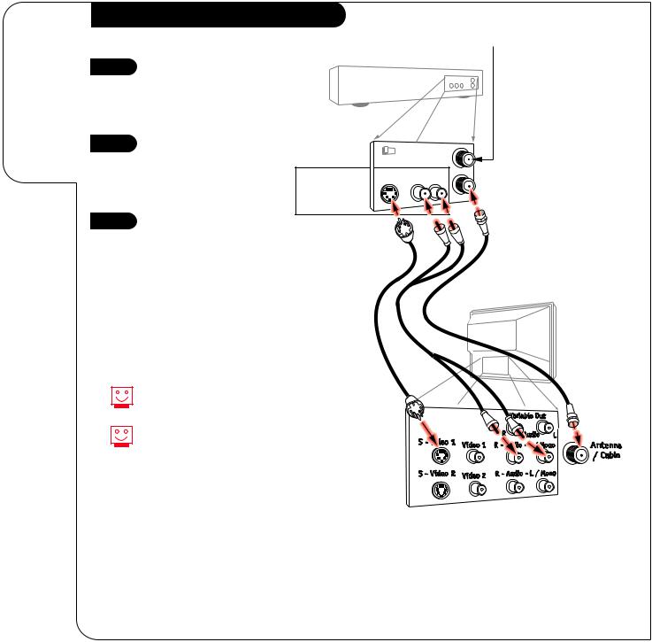
Connecting a S-VHS VCR or DVD Player to your
Entertainment Machine.
Super VHS VCR/DVD Player
Super VHS VCR
1 |
Locate the Ant In jack on the |
|
back of your S-VHS VCR. |
||
|
||
|
Connect the cable line coming |
|
|
from your wall directly to |
|
|
this jack. |
|
2 |
Now locate the Out to TV |
|
jack. Connect a cable from |
||
|
||
|
the Out to TV jack to the |
|
|
Antenna/Cable jack on |
|
|
the back of your TV. |
|
3 |
Find the audio and S-Video |
|
jacks on the back of your |
||
|
||
|
S-VHS VCR, and connect them |
|
|
following the instructions pro- |
|
|
vided with your equipment. |
DVD* Player
Simply connect the S-Video/Audio out on the DVD to the S-VHS 1, R-L Audio or S-VHS 2, R-L Audio In on the TV.
Use Video sources for better picture and sound.
To use with PIP: go to the Source Menu (page 30) and choose the jack you’ve connected your S-VHS (S-VHS 1,-2) as the Main or PIP source.
|
Attach to |
|
cable wall jack, |
Super VHS VCR |
cable box, or |
antenna |
|
Back AV panel |
|
||
|
|
|
|
In |
|
3 |
4 |
|
|
DVD Player |
S-Video |
Audio |
Out |
|
Out |
R-L Out |
|
||
Jacks |
|
|
|
|
Cables
not included with TV
TV back
* Digital Video Disk Player
3374-O |
3375-O |
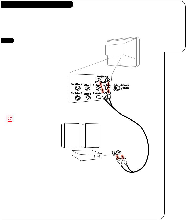
Audio Hook-ups
Before you begin plugging in your stereo system, it’s a good idea to put it in its approximate place first. That way you know how much wire you have or will need.
1 |
Locate the jacks marked |
|
Variable Out. These are for the |
|
|
|
|
|
|
stereo system. Connect the |
|
|
stereo system’s cables, accord- |
|
|
ing to their color (red is the |
|
|
right channel, white the left) |
|
|
to these jacks. |
|
|
|
|
|
|
|
These wires should be included with your stereo system.
INSTALLATION |
STEREO SYSTEM |
P A G E 9 |
|
|
|
Get the best sound possible from your
Entertainment Machine.
TV back
A/V cables not included with TV
R-L Audio
Input
Stereo
System
3375-O
P A G E 1 0 |
INSTALLATION |
AUTO PROGRAM |
|
|
|
Use Auto Program to automatically find and store all of the stations available in your area in the TV’s memory.
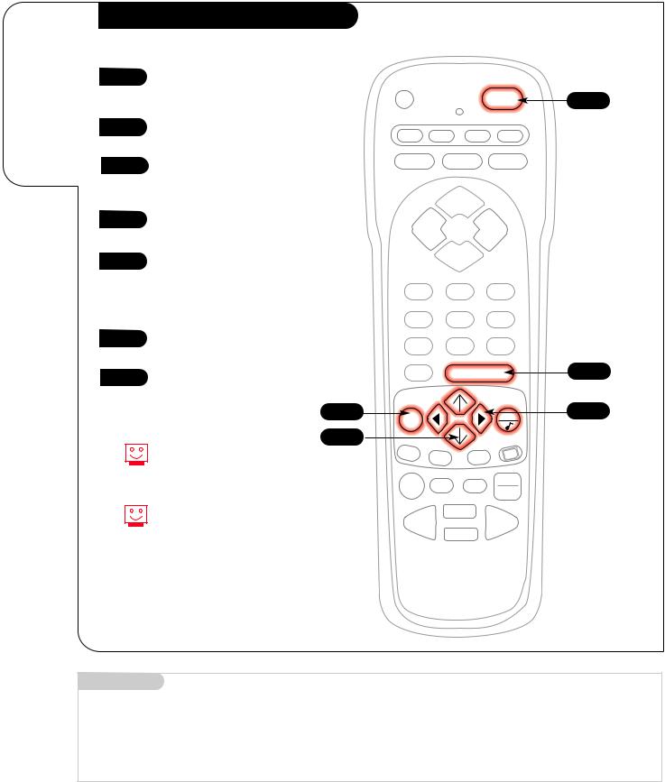
Auto Program
1 |
With the remote control in hand, |
|
press the POWER key to turn on |
||
|
||
|
your Entertainment Machine. |
|
2 |
Press the MENU key so the Setup |
|
|
||
|
menu appears. |
|
3 |
Using the UP/DOWN arrows on |
|
|
||
|
the remote control, select Auto |
|
|
Program on your screen. |
1
CABLE VCR AUX TV
 SURF FLASHBK MUTE
CHANNEL
4 |
Press a RIGHT or LEFT arrow to |
|
|
|
|
|
|
|
|
|
|
|
|
|
reach the Auto Program screen. |
VOLUME |
|
VOLUME |
||
5 |
Using the UP/DOWN arrows, |
|
|
CHANNEL |
|
|
choose either Cable TV or Off-Air |
|
|
|
|
|
|
|
|
|
|
|
|
|
|
Antenna on your screen. |
1 |
|
2 |
|
3 |
|
Note: The option that is blinking |
|
|
|||
|
and appears in white is selected. |
4 |
|
5 |
|
6 |
6 |
|
|
|
|||
Press a RIGHT or LEFT arrow to |
7 |
|
8 |
|
9 |
|
begin Auto Program. |
|
|
||||
|
|
|
||||
7 |
TV viewing. |
|
|
|
|
|
|
|
|
|
|
|
|
|
|
2 |
|
|
|
|
|
Note: Auto Program finds channels |
3/5 |
|
|
|
|
|
PIP |
|
|
|
CC |
|
|
being received by the TV Tuner. See |
PIP ch |
FREEZ |
|||
|
|
|
||||
|
|
|
|
|
|
|
|
information on page 14 for using |
|
|
|
|
TV/VCR |
|
the Cable Box or VCR Tuners. |
RECORD PAUSE |
TIMER |
|||
|
SOURCE |
|||||
|
|
|
|
|
|
|
|
To customize your channel |
|
|
PLAY |
|
|
|
selection, see page 18. |
REWIND |
|
FFWD |
||
|
|
|
|
|
|
|
STOP
Mini glossary
AUTO PROGRAM Auto Program is how your Entertainment Machine finds all the channels available in your area and stores them in memory.
3375-O
OPERATION |
REMOTE KEY FUNCTIONS |
TV MODE |
P A G E 1 1 |
|
|
|
|
TV Mode Remote Key Functions
PRG (PROGRAM)
Programs your remote to operate other products.
See page 35.
FLASHBK (FLASHBACK)
Return to the last channel viewed.
SURF
Activates custom channel select mode on your Entertainment Machine.
When Surf mode is active, CHANNEL UP/DOWN keys “Surf” through the channels you’ve selected.
CHANNEL (UP/DOWN)
Flip through available channels.
ENTER
Shows the Channel/Time display. Press after channel numbers for instant selection.
LEFT/RIGHT ARROWS
The Left/Right arrows adjust options.
MENU
Displays on-screen menus for TV mode. See page 16
PIP FEATURES
For PIP (Picture-in-Picture) operation. See page 32
PRG |
POWER |
CABLE VCR AUX TV
 SURF FLASHBK MUTE
CHANNEL
VOLUME VOLUME
CHANNEL
1 2 3
4 5 6
7 8 9
0 ENTER
MENU |
QUIT |
|
PIP |
PIP ch |
FREEZ |
|
||
RECORD PAUSE |
TV/VCR |
|
TIMER |
||
SOURCE
TIMER
Displays the Sleep Timer |
PLAY |
|
FFWD |
||
REWIND |
||
Menu. See “Timer Setup” |
STOP |
|
on page 24 for |
||
|
||
more information. |
|
Keys dedicated to VCR functions will still operate your VCR while the remote is in TV mode.
remote control part number
MBR3458
(124-212-51)
A quick list of all the keys on your remote and what they do.
POWER
Turns TV On or Off.
LED INDICATOR LIGHT
Lights when keys are pressed.
CABLE/VCR/AUX/TV
Selects remote operating mode.
MUTE
Turns sound Off and On while the picture remains.
Press once to quiet sound, press again to mute, press again to restore sound.
VOLUME LEFT/RIGHT
Adjusts the sound levels on your Entertainment Machine.
NUMBER KEY PAD
Selects channels directly and enters numeric values for some options.
UP/DOWN ARROWS
The Up/Down arrows select options.
QUIT
Removes on-screen display from view. If no display is on, switches SEQ sound feature On and Off on some TVs.
CC(CLOSED CAPTIONING)
Displays the closed caption menu.
TV/VCR-SOURCE
Switches between watching TV through your antenna/cable, or through your VCR.
3375-O
P A G E 1 2 |
OPERATION |
BUTTON FUNCTIONS |
|
|
|
|
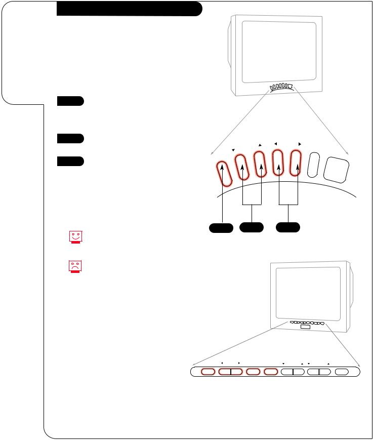
Front Panel Diagram |
How to use |
|
your front |
|
control |
Note: For model A27B41, when using the on- |
panel to |
screen menus, the buttons on the front panel |
operate |
correspond to the remote control buttons as |
the menus. |
follows: |
|
VOLUME = Adjust Left/Right |
|
CHANNEL = Select Up/Down |
1 |
To access the Setup menu, press |
|
|
||
|
the MENU button once; to get the |
|
|
other menus, keep pressing the |
|
|
MENU button. |
|
2 |
Choose the function you wish to |
|
change using the SELECT button. |
||
|
||
3 |
The ADJUST buttons act as an |
|
“adjustment” (Left/Right) func- |
||
|
||
|
tion. |
Typical 6-Button TV Front Panel
CHANNEL |
VOLUME |
POWER |
|
1 2
Menus disappear after five seconds. To get them back, push the MENU button again.
If you’ve lost your remote, you can get a new replacement by calling 1-800-255-6790 to purchase a replacement.
ENTER |
ADJUST |
SELECT MENU |
VOLUME |
CHANNEL |
POWER |
Typical 10-Button TV Front Panel
3375-O
OPERATION TV FUNDAMENTALS P A G E 1 3
Basic Television Operation
Source
The source button (TV/VCR/Source) on the remote switches between Video input and Cable/Antenna input. The Time/Channel display will read “Video” in place of a channel number if A/V inputs are selected as the picture source.
Cable/Antenna Input: This setting allows you to change cable or antenna channels and to view videocassettes on channel 3 (or 4) in mono sound.
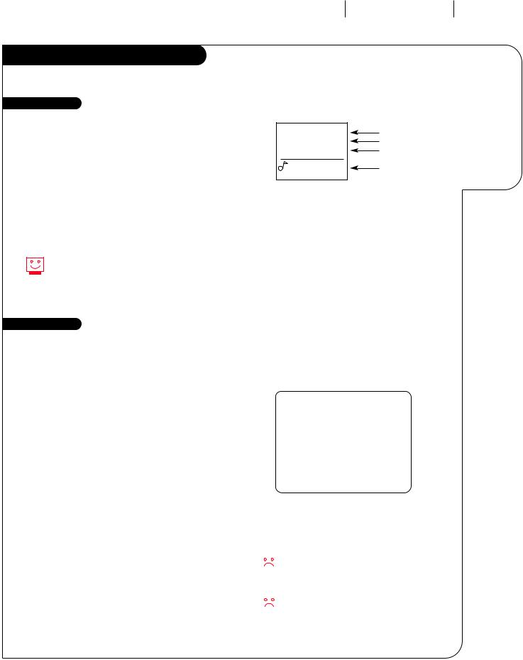
Ch 12-MTV |
10:55 |
Stereo |
PIP Ch 30-ABC |
Introducing you to the basics of your Entertainment Machine
Channel/Label or Video (Indicates Source) Time
Audio Mode
PIP Channel & Label
(Note Shows Source of sound)
Video Input: This setting allows stereo playback of videocassettes. The television cannot change channels in the Video mode, but the VCR can.
To view the current input source, press ENTER on your remote. The Time/Channel display should appear in the upper right hand corner of the screen. If the display reads ‘Video,’ then the source is an A/V input. If the display reads a channel number, then the source is your Cable or Antenna.
XDS Data Feature
XDS = Extended Data Service
Some broadcasters are including on the signal they provide additional information (data) about the program. This data (see example) appears on your TV screen when you press ENTER; if the channel has XDS.
Date |
|
|
|
|
|
|
|
|
|
Jan/30/98 |
|
|
Ch 25-MTV |
|||
|
|
|
|
|
|
|
|
|
|
|
7:55 |
|
|
|||
|
|
|
|
|
|
|
|
|
|
|
|
|
|
|
||
|
|
|
|
|
|
|
|
|
|
|
|
|
|
Stereo |
||
Channel/Time/Audio Display |
|
|
|
|
|
|
|
|
|
|
|
|
|
|
||
|
|
|
|
|
PIP Ch 30-ABC |
|||||||||||
|
|
|
|
|
|
|
|
|
|
|||||||
(shown with PIP display, if PIP is on) |
|
|
|
|
|
|||||||||||
|
|
|
|
|
|
|
|
|
||||||||
Title of Program |
|
|
|
|
NOVA |
|||||||||||
Length of Program (in hours and minutes) |
|
|
|
|
|
|
|
|
|
|||||||
|
|
|
|
|
|
|
|
|||||||||
Time Remaining (in hours and minutes) |
|
|
|
|
|
|
|
|
|
|||||||
|
|
Length 00:44 |
Time Left 00:37 |
|||||||||||||
|
||||||||||||||||
Showing XDS Data |
|
|
|
Example of an XDS Data Display |
||||||||||||
Select a channel. Press ENTER to display XDS data; if available. |
|
|
|
|||||||||||||
|
|
|
|
|
|
|
|
|
||||||||
XDS Channel Labels |
|
|
|
|
|
|
|
|
|
|||||||
XDS can provide a channel label automatically. For the pro- |
|
|
|
At this printing, XDS data is only being provided |
||||||||||||
grams to display an XDS channel label, select the dashes |
|
|
|
|
|
|
|
|||||||||
(- - - -) for that channel from the Channel ID option in the |
|
|
|
|
|
|
|
by some public broadcasting stations; and as a |
||||||||
|
|
|
|
|
|
|
||||||||||
Setup Menu. |
|
|
|
result, it is only available on some channels. |
||||||||||||
|
|
|
|
|
|
|
|
|
|
|
You must set the Clock in the Setup Menu |
|||||
|
|
|
|
|
|
|
|
|
|
|
||||||
|
|
|
|
|
|
|
|
|
|
|
before the time will appear on the |
|||||
|
|
|
|
|
|
|
|
|
|
|
||||||
|
|
|
|
|
|
|
|
|
|
|
Channel/Time Display or on the XDS display. |
|||||
3375-O
P A G E 1 4 |
OPERATION |
TV FUNDAMENTALS |
|
|
|
Introducing you to the basics of your Entertainment Machine
Basic Television Operation (cont’d)
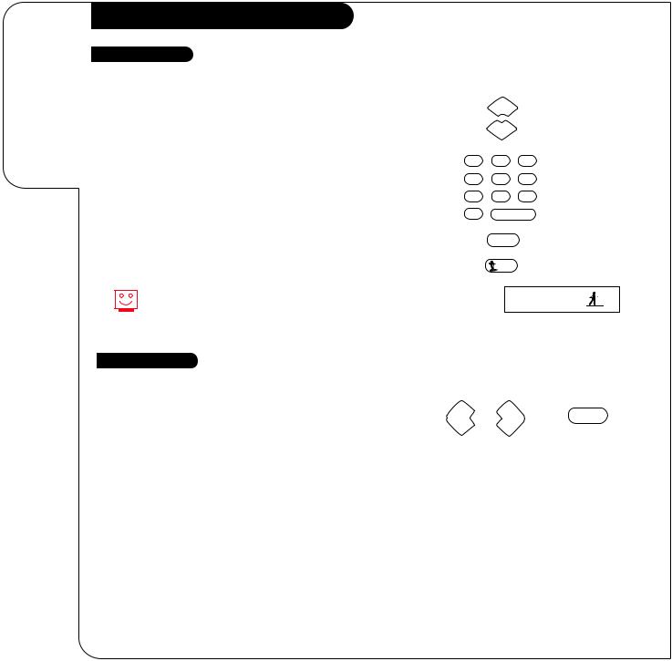
Changing Channels
CHANNEL UP/DOWN arrows: Use these arrows to change the channels. Autoprogram will have found all channels available to you.
NUMBER Key Pad: To skip to any channel, enter the number of the channel using the NUMBER key pad, then press ENTER.
CHANNEL
CHANNEL
1 2 3
FLASHBACK: To instantly return to the last channel viewed, |
4 |
5 |
6 |
|
press FLASHBACK. |
|
|||
7 |
8 |
9 |
|
|
|
|
|||
SURF: Switches between the primary channel selection and your cus- |
0 |
|
ENTER |
|
tomized surf channel selections. The surf mode icon will appear in the |
|
|
|
|
lower right corner of the screen when you change channels. Press SURF |
|
FLASHBK |
|
|
to turn surf On, press again to turn surf mode Off. |
|
|
|
|
|
|
SURF |
|
|
This is while the source is set to Antenna/Cable. For any other |
|
|
Surfing |
|
source, such as a VCR, the Main Picture channel changing will |
|
|
|
|
|
|
|
|
|
be controlled by that equipment. |
|
|
|
|
Audio |
|
|
|
|
Volume Right/Left: To adjust the volume level, use the volume |
|
|
|
|
Right/Left arrows. To silence your TV instantly, press MUTE once to |
VOLUME |
|
VOLUME |
MUTE |
|
|
|
||
soften the volume, press again to turn sound off. To get the sound back, press MUTE again.
3374-O

OPERATION |
TV FUNDAMENTALS |
P A G E 1 5 |
|
|
|
Basic Television Operation (cont’d)
There are a number of ways you can choose to integrate your Entertainment Machine with the rest of your equipment. Channels can be changed using the television, the VCR, or the cable box, with advantages to each.
USING THE TELEVISION AS THE TUNER preserves all your channel labels (not available on some models). It also reduces the number of keys on the remote control you need to worry about. (One device, one remote to learn.)
USING THE VCR AS THE TUNER has the advantage of simplifying the recording process. If the VCR is tuned to channel seven, then the VCR will record channel seven.
USING THE CABLE BOX (if you have one) to change the stations sometimes has an advantage, too, especially if your cable provider requires you to use their cable box to descramble their stations.
Setting Up a Tuner
1 |
Based on the advantages listed above, decide what |
|
device you want to use as the tuner. |
||
|
||
2 |
Connect the antenna or cable source to the input |
|
|
of your tuner. (If you chose your television as the |
|
|
tuner, then you’re done. Go watch your |
|
|
Entertainment Machine.) |
|
3 |
Connect the output of your tuner to the input of the |
|
|
next device. |
4 |
If you used A/V cables for step 3, set the “next |
|
device” to Video input. If you used an RF coaxial |
||
|
||
|
cable in step 3, then tune the “next device” to |
|
|
match the output channel of your tuner (usually |
|
|
channel 3 or 4). |
|
5 |
Repeat steps 3 and 4 until you reach your |
|
|
||
|
Entertainment Machine. Then enjoy! |
Help on combining your Entertainment Machine
with more equipment.
Mini glossary
TUNER |
The television, VCR, or cable box that you choose to change channels with. |
3374-O
 Loading...