


Color profile: Disabled
Composite Default screen
User's Guide
For the Zebra Z4000™ and Z6000™ Printers
Customer order # 77460L Manufacturer part # 77460LB Rev. 2
1
H:...uspiran2.vp
Thu Jun 18 15:49:04 1998

Color profile: Disabled
Composite Default screen
Proprietary Statement
This manual contains proprietary information of Zebra Technologies Corporation. It is intended solely for the information and use of parties operating and maintaining the equipment described herein. Such proprietary information may not be used, reproduced, or disclosed to any other parties for any other purpose without the expressed written permission of Zebra Technologies Corporation.
Product Improvements
Continuous improvement of products is a policy of Zebra Technologies Corporation. All specifications and signs are subject to change without notice.
FCC Compliance Statement
NOTE: This equipment has been tested and found to comply with the limits for a Class B digital device, pursuant to Part 15 of the FCC Rules. These limits are designed to provide reasonable protection against harmful interference in a residential installation. This equipment generates, uses and can radiate radio frequency energy and, if not installed and used in accordance with the instructions, may cause harmful interference to radio communications. However, there is no guarantee that the interference will not occur in a particular installation. If this equipment does cause harmful interference to radio or television reception, which can be determined by turning the equipment off and on, the user is encouraged to try to correct the interference by one or more of the following measures:
nReorient or relocate the receiving antenna.
nIncrease the separation between the equipment and the receiver.
nConnect the equipment into an outlet on a circuit different from that to which the receiver is connected.
nConsult the dealer or an experienced Radio/TV technician for help.
NOTE: This unit was tested with shielded cables on the peripheral devices. Shielded cables must be used with the unit to insure compliance.
“The user is cautioned that any changes or modifications not expressly approved by Zebra Technologies Corporation could void the user’s authority to operate the equipment.”
Canadian DOC Compliance Statement
This digital apparatus does not exceed the Class A limits for radio noise emissions from digital apparatus as set out in the radio interference regulations of the Canadian Department of Communications.
Liability Disclaimer
Zebra Technologies Corporation takes steps to assure that its published Engineering Specifications and Manuals are correct; however, errors do occur. Zebra Technologies Corpora tion reserves the right to correct any such errors and disclaims liability resulting therefrom.
No Liability for Consequential Damage
In no event shall Zebra Technologies corporation or anyone else involved in the creation, production, or delivery of the accompanying product (including hardware and software) be liable for any damages whatsoever (including, without limitation, damages for loss of business profits, business interruption, loss of business information, or other pecuniary loss) arising out of the use of or the results of use of or inability to use such product, even if Zebra Technologies Corporation has been advised of the possibility of such damages. Because some states do not allow the exclusion or limitation of liability for consequential or incidental damages, the above limitation may not apply to you.
Copyrights
This copyrighted manual and the label printers described herein are owned by Zebra Technologies Corporation. All rights are reserved. Unauthorized reproduction of this manual or the software in the label printer may result in imprisonment of up to one year and fines of up to $10,000 (17 U.S.C.506). Copyright violators may be subject to civil liability.
IBM® is a registered trademark of IBM Corporation.
Goo Gone® is a Registered Trademark of Magic American Corporation
Zebra®, Stripe®, ZPL®, and ZPL II® are registered trademarks, and Z Series,
Z4000, and Z6000 are trademarks of Zebra Technologies Corporation.
© Zebra Technologies Corporation
2
H:...uspiran2.vp
Thu Jun 18 15:49:05 1998

Color profile: Disabled
Composite Default screen
|
|
i |
Z Series™ User’s Guide |
||
3 |
|
|
H:...uspiran2.vp
Thu Jun 18 15:49:10 1998

Color profile: Disabled
Composite Default screen
ii |
Z Series™ User’s Guide |
|
4 |
H:...uspiran2.vp |
|
Thu Jun 18 15:49:10 1998 |
|

Color profile: Disabled
Composite Default screen
Contents
Welcome
Getting Started |
1 |
Communications |
2 |
Printer Power |
2 |
Printer Configuration
Z Series™ Configuration |
3 |
Media & Ribbon Loading
Loading Media |
5 |
Loading Ribbon |
7 |
Removing Ribbon |
8 |
Media Sensor Positioning
Media Sensor Operation |
9 |
Media Sensor Position |
9 |
Printer Operational Check |
10 |
Printer Operation
Operator Interface |
13 |
Front Panel Keys |
13 |
Front Panel LEDs |
14 |
Additional Front Panel Controls |
14 |
Z Series™ User’s Guide |
iii |
5 |
|
H:...uspiran2.vp
Wed Jul 08 11:23:52 1998

Color profile: Disabled
Composite Default screen
Media Calibration
Auto-Calibration |
17 |
Calibration Control |
17 |
Care & Adjustments
Cleaning |
19 |
Lubrication |
24 |
Printhead Pressure Adjustment |
24 |
Power Rewind/Power Peel |
|
Media Alignment |
25 |
Printer Options
LCD Display (Deluxe Front Panel) |
27 |
Power Rewind/Power Peel Option |
28 |
Value Peel Option |
30 |
Cutter Option |
31 |
Electronics Options |
33 |
Communication Options |
33 |
Troubleshooting
Power On Self-Test |
35 |
Troubleshooting Tables |
35 |
Printer Self-Tests |
38 |
Resetting Factory Defaults |
44 |
Initializing the Flash Memory and PCMCIA Card |
45 |
Automatically Executed Format |
45 |
Print Error Conditions |
46 |
iv |
Z Series™ User’s Guide |
6
H:...uspiran2.vp
Wed Jul 08 11:23:52 1998

Color profile: Disabled
Composite Default screen
Printer Specifications
General Specifications |
47 |
Printing Specifications |
48 |
Ribbon Specifications |
48 |
Media Specifications |
49 |
Zebra Programming Language (ZPL II®) |
50 |
Bar Codes |
50 |
Standard Printer Fonts |
51 |
Optional Printer Fonts |
53 |
Appendix A
Printer Configuration
Printer Configuration
(Standard Front Panel) |
55 |
(Deluxe Front Panel) |
59 |
Appendix B
Communication Interfaces |
69 |
Serial Data Communications |
69 |
Parallel Data Communications |
72 |
Appendix C
AC Power Cord |
73 |
Fuse Replacement |
74 |
Shipping |
74 |
Setting Darkness For “In-Spec” Bar Codes |
74 |
ASCII Code Chart |
77 |
Glossary
Index
Z Series™ User’s Guide |
v |
7 |
|
H:...uspiran2.vp
Wed Jul 08 11:23:52 1998

Color profile: Disabled
Composite Default screen
vi |
Z Series™ User’s Guide |
|
8 |
H:...uspiran2.vp |
|
Wed Jul 08 11:23:52 1998 |
|

Color profile: Disabled
Composite Default screen
Welcome
Congratulations! You have just purchased a high-quality thermal demand printer manufactured by the industry leader in quality, service, and value. For over 25 years, Zebra Technologies Corporation has provided customers with the highest caliber of products and support.
This user’s guide provides all the information you will need to operate the printer on a daily basis.
To create and print label formats, refer to the ZPL II Programming Guide (part # 46469L). This guide is available by contacting your distributor or Zebra Technologies Corporation.
In addition, label preparation software is available. Contact your distributor or Zebra Technologies Corporation for further information.
The Z Series™ Maintenance Manual (part # 77450L) contains the information you may need to properly maintain your printer.
Getting Started
Unpacking
Save the carton and all packing materials in case shipping is required.
Inspect the printer for possible shipping damage:
nCheck all exterior surfaces for damage.
nRaise the Media Access Door and inspect the Media Compartment for damage.
Reporting Damage
If you discover shipping damage:
nImmediately notify the shipping company and file a damage report.
nRetain the carton and all packing material for inspection.
nNotify your local Zebra distributor of the damage.
Zebra Technologies Corporation is not responsible for any damage incurred during shipment of the printer and will not cover the repair of this damage under its warranty policy. Any damage claim should be filed with the shipping company.
Z Series™ User’s Guide |
1 |
9 |
|
H:...uspiran2.vp
Mon Jun 22 10:28:44 1998
Color profile: Disabled
Composite Default screen
For shipping information, refer to Appendix C.
Communications
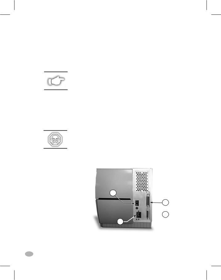
Refer to Figure 1. The Z Series™ printer comes standard with both an Electronics Industries Association (EIA) RS-232 serial data interface(a) and a bi-directional parallel interface(b) compliant with the IEEE1284 standard. The serial interface is also configured for both RS-422/ RS-485 single drop and RS-485 multi-drop communication modes.
NOTE: You must supply the interface cable for your application. See
Appendix B of this manual for specific cable requirements.
Printer Power
The Power Supply in the Z Series™ printer automatically detects the applied line voltage and works in the 90 to 265 VAC range.
Refer to Figure 1. The AC Power Cord must have a three-prong female connector on one end which plugs into the mating connector(c) at the rear of the printer. If a power cable was not included with your printer, refer to Appendix C at the back of this guide.
WARNING!! For personnel and equipment safety, always use a three-prong plug with an earth ground connection to the AC Power Source.
Refer to Figure 1. Insure that the AC Power ON/OFF Switch(d) is in the OFF (O) position before connecting the AC Power cord to a nearby electrical outlet.
d
b

 a c
a c 
Figure 1. Printer Rear View
2 |
Z Series™ User’s Guide |
10
H:...uspiran2.vp
Mon Jun 22 10:28:46 1998
Color profile: Disabled
Composite Default screen
Printer Configuration
Z Series™ Configuration
The Z Series™ printer will have one of two different styled front panels. The deluxe front panel contains an LCD (Liquid Crystal Display), but the standard front panel does not. With the deluxe front panel, the LCD displays the parameters during the configuration process. For those printers with the standard front panel, two banks of eight miniature switches located inside the printer’s front panel access door are used when configuring the printer.
Communications Parameters
The Z Series™ printer is equipped with both serial data and parallel data communication interfaces. This permits two sources to send label formats to the printer.
The first source to send a “Start of Label Format” command controls the printer. The printer will send a “printer busy” command to the second source to inhibit data transmission.
The serial interface is factory preset to match the typical PC environment with RS232 communication:
9600 Baud, 8 Data Bits,
No Parity, Xon/Xoff Handshaking.
If you need to change your printer’s serial communications settings to match those of your host computer, refer to Appendix A. If you do not know the settings of your host computer, refer to the instruction manual provided with the computer or your software application.
See Appendix B of this guide for specific data communication cable requirements.
The printer automatically senses if a parallel communications cable is connected from your host computer.
Z Series™ User’s Guide |
3 |
11 |
|
H:...uspiran2.vp
Thu Jun 18 15:51:22 1998

Color profile: Disabled
Composite Default screen
Operating Modes
When shipped from the factory, the printer is preset to the most commonly used modes of operation:
Tear-Off Mode, Thermal Transfer Printing,
Die-Cut Media, Serial Port RS-232 Communications.
Refer to Appendix A to configure the parameters for the following:
nOptions, such as Power Rewind/Power Peel, Value Peel, or Cutter
n n n n
Operating Modes
Print Darkness
Label Tear-Off/Cut-Off Position
Image Position on the label
4 |
Z Series™ User’s Guide |
|
12 |
H:...uspiran2.vp |
|
Thu Jun 18 15:51:22 1998 |
|
Color profile: Disabled
Composite Default screen
Media & Ribbon Loading
Loading Media
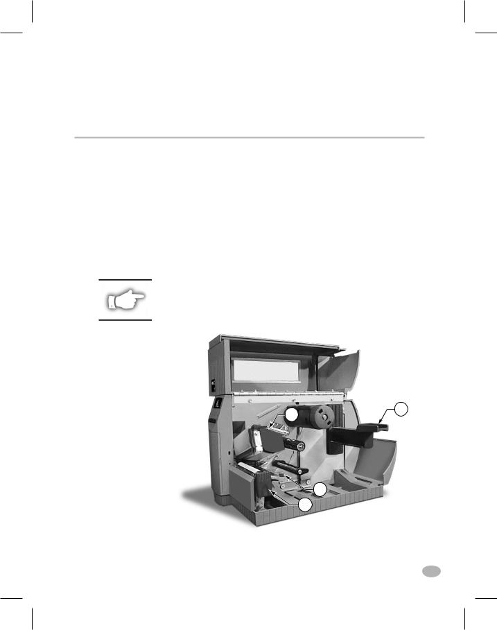
To load media, refer to Figure 2.
1.Raise the media cover.
2.Press the Printhead Open Lever(e).
[The Printhead Assembly(f) automatically springs up.]
3.Fold down the Media Supply Guide(g) and slide it out as far from the printer frame as possible.
4.Slide the Media Guide(h) out as far from the printer frame as possible.
5.Determine the type of media required for your application and follow the roll media or fanfold media loading procedure.
NOTE: If your printer has either the Power Rewind/Power Peel, Value Peel, or Cutter option installed, refer to the Options section for media loading instructions.
f |
g |
|
h |
|
e |
|
Figure 2. Loading Media |
|
Z Series™ User’s Guide |
5 |
13 |
|
H:...uspiran2.vp
Thu Jul 02 09:48:43 1998
Color profile: Disabled
Composite Default screen
Roll Media Loading
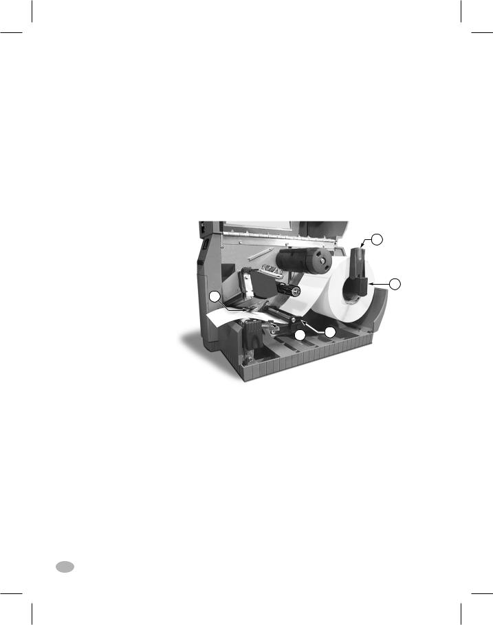
To load roll media, refer to Figure 3.
1.Place the roll of media on the Media Supply Hanger(i) and push it on all the way.
2.Fold the Media Supply Guide(g) up and slide it against the outer edge of the media roll.
3.Feed the media under the Media Spindle(j), under the Ribbon Sensor(k), and out the front of the printer.
4.Slide the Media Guide(h) in until it is against the outer edge of the media.
5.Close the Printhead Assembly and the Media Cover, or continue to "Loading Ribbon".
g
i
k
 h
h  j
j
Figure 3. Roll Media Loading
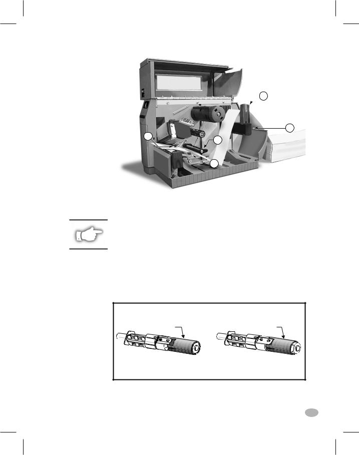
Fanfold Media Loading
To load fanfold media, place the media behind the printer and refer to
Figure 4.
1.Pass the fanfold media over the Media Supply Hanger(i).
2.Fold the Media Supply Guide(g) up and slide it against the outer edge of the media.
3.Feed the media under the Media Spindle(j), under the Ribbon Sensor(k), and out the front of the printer.
4.Slide the Media Guide(h) against the outer edge of the media.
5.Close the Printhead Assembly and the Media Cover, or continue to "Loading Ribbon".
6 |
Z Series™ User’s Guide |
14
H:...uspiran2.vp
Thu Jul 02 09:48:45 1998
Color profile: Disabled
Composite Default screen
 g
g
i
k |
j |
|
 h
h
Figure 4. Fanfold Media Loading
Loading Ribbon
NOTE: The Ribbon Supply Spindle in your printer may be a "Dual-Tension" variety. Most applications require the spindle to be in the "Normal" position. The "Low-Tension" position is recommended only when wide ribbons are used and normal tension hampers the ribbon movement.
To place this spindle in the "Normal" position, firmly pull out on the Spindle End-Cap until it clicks into place as shown in Figure 5a. To place the spindle in the "Low-Tension" position, firmly push in on the Spindle End-Cap until it clicks into place.
SPINDLE END-CAP |
SPINDLE END-CAP |
EXTENDED |
RETRACTED |
Normal Position |
Low Tension Position |
Figure 5a. Ribbon Supply Spindle Positioning
Z Series™ User’s Guide |
7 |
15 |
|
H:...uspiran2.vp
Thu Jul 02 09:48:48 1998

Color profile: Disabled
Composite Default screen
Loading the Ribbon
CAUTION: Always use ribbon that is wider than the media. The smooth backing of the ribbon protects the printhead from wear. (For Direct Thermal printing, do not load ribbon in the printer.)
To load ribbon, refer to Figures 5a and 5b.
1.Place the roll on the Ribbon Supply Spindle(l) and push it on all the way.
2.Pull the end of the ribbon over the Ribbon Sensor(k), under the Printhead assembly(f), and up over the Ribbon Guide Plate(m).
3.Wind the ribbon onto the Take-up Spindle(n) for several turns in a clockwise direction.
4.As you close the Printhead Assembly, keep the ribbon snug and free of wrinkles, and in line with the guide mark near the left edge of the Ribbon Guide Plate.
 n
n
m |
f |
|
l
 k
k
Figure 5b. Ribbon Loading
Removing Ribbon
To remove the ribbon, turn the Release Knob on the end of the Take-up
Spindle(n) counterclockwise and slide the ribbon off the Spindle.
8 |
Z Series™ User’s Guide |
16
H:...uspiran2.vp
Thu Jul 02 09:48:50 1998

Color profile: Disabled
Composite Default screen
Media Sensor Positioning
Media Sensor Operation
When the printer is turned ON, a Power ON Self Test is performed which checks the status of the electronic system and controls within the printer. Additional operating parameters are determined by the type of media being used and the position of the Media Sensor located behind the Platen and under the media.
Non-Continuous (Labels, Notched Tags) Media
This type of media has some type of physical characteristic (notch, black mark, gap between die-cut labels, etc.) which indicates the start- of-label position. The Media Sensor must be properly positioned to sense these indicators.
Continuous Media
Continuous media typically does not contain start-of-label indicators.
Label length must be specified by commands sent to the printer.
If you are using ZPL II, include a Label Length (^LL) command in each label format you send to the printer (refer to your ZPL II Programming Guide). If you are using other software to drive your printer, refer to the instructions provided with that software.
Media Sensor Position
1.To properly position the Media Sensor(o), refer to Figure 6.
2.With the Printhead Assembly open, turn the AC Power ON
3.Look through the side of the print mechanism and locate the Media Sensor Positioning Lever(p).
4.(non-continuous media - labels, notched tags) Move the lever across the width of the media to position the sensor in line with the start-of-label indicator (notch, black mark, gap between die-cut labels, etc). The glow of the red LED through the media can help to accurately position the sensor.
(continuous media - no notch or opening to sense) Position the
Z Series™ User’s Guide |
9 |
17 |
|
H:...uspiran2.vp
Thu Jun 18 15:54:02 1998

Color profile: Disabled
Composite Default screen
sensor anywhere under the media so that an “Out-of-Media” condition will still be sensed.
5.Insure the media and ribbon are properly positioned within the print mechanism. then close the Printhead Assembly.
6.Close the printer’s media cover, then turn the printer power OFF.
 o
o
 p
p
Figure 6. Sensor Positioning
Printer Operational Check
1.To insure proper setup and to check the initial printer configuration, press and hold the CANCEL key while turning the printer power ON. (Release the CANCEL key once the front panel indicators begin to turn OFF.)
2.After an initial time period when the Power ON Self Test is performed, the printer will feed out media while calibrating the label length, then print a configuration label.
3.Check the current configuration printed on the label and note any parameters which must be changed to insure the printer fits your application. For information on changing the configuration for your specific application, refer to Appendix A.
A visual check of the label also provides an indication of the print quality. Media width and media thickness vary from one application to the
10 |
Z Series™ User’s Guide |
18
H:...uspiran2.vp
Thu Jun 18 15:54:04 1998
Color profile: Disabled
Composite Default screen
next. To maintain proper print quality, refer to the Care & Adjustments section later in this guide.
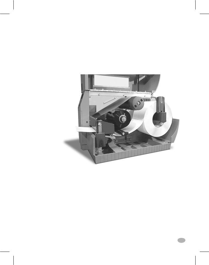
Figure 7 illustrates a properly loaded Z Series™ printer. For loading media and ribbon in printers with the Power Rewind/Power Peel, Value Peel or Cutter options, see the Options section later in this guide.
Figure 7. Printer Ready for Operation
Z Series™ User’s Guide |
11 |
19 |
|
H:...uspiran2.vp
Thu Jun 18 15:54:07 1998

Color profile: Disabled
Composite Default screen
12 |
Z Series™ User’s Guide |
|
20 |
H:...uspiran2.vp |
|
Thu Jun 18 15:54:08 1998 |
|
Color profile: Disabled
Composite Default screen
Printer Operation
Operator Interface
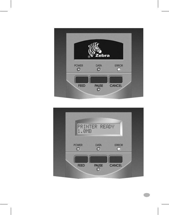
The Z Series™ family of printers features either a standard or deluxe front panel. The deluxe front panel features a Liquid Crystal Display (LCD) that provides both printer status information and configuration option menus. This section of the user’s guide presents information which is common to both printer front panels. Refer to Figures 8 and 9 to locate the keys and LEDs discussed in this section.
Front Panel Keys
Feed Key
The FEED key forces the printer to feed one blank label. If you press the FEED key while the printer is idle or paused, a blank label is fed immediately. If you press the FEED key while the printer is printing, one blank label is fed after the completion of the current batch of labels. Once the blank label has been fed, pressing the FEED key again will feed a second label.
Pause Key
The PAUSE key stops and restarts the printing process. The first time you press the PAUSE key, any partially printed label is completed; then the printing process is stopped. If the printer is idle when you press the PAUSE key, no new print requests are accepted. Press the PAUSE key a second time to resume the printing process.
Cancel Key
The CANCEL key only functions when the printer is paused. When you press the CANCEL key, the label format that is currently printing is canceled. If no label format is printing, then the next one to be printed is canceled. If there are no label formats stored in the printer and waiting to be printed, the CANCEL key is ignored.
If you press the CANCEL key for an extended period of time (more than 3 seconds) the printer performs a “cancel all formats” operation. The printer discards all of the label format data it has received, and returns to the idle state.
Z Series™ User’s Guide |
13 |
21 |
|
H:...uspiran2.vp
Thu Jun 18 15:54:51 1998

Color profile: Disabled
Composite Default screen
Front Panel LEDs
LEDs on the front panel are a quick indication of the printer's status.
The LEDs listed below are common to all Z Series™ printers .
POWER LED
The POWER LED is always ON when the printer is turned ON.
DATA LED
The DATA LED is normally OFF. When data is received, the LED acts as follows:
n SLOW BLINK - |
Printer is unable to accept more data |
|
from the host |
n FAST BLINK - |
Printer is receiving data |
n LED ON - |
No data being received - data processing |
|
or printing still occurring. |
The DATA LED will also blink once when the CANCEL key is pressed and a format is successfully canceled.
ERROR LED
The ERROR LED is normally OFF. When an error occurs that causes an interruption in the printing process, the LED acts as follows:
n SLOW BLINK - |
Ribbon In Warning, Under Temp |
|
Warning, or Over Temp Error |
n FAST BLINK - |
Printhead Open |
n LED ON - |
Media Out, Ribbon Out, or Cutter Errors |
With the Deluxe Front Panel, the type of error will also be visible on the Liquid Crystal Display.
PAUSE LED
The PAUSE LED is normally OFF. When the LED is ON it indicates the printer has stopped all printing operations. If the printer is printing when a PAUSE condition is requested, the LED turns ON at the end of the current label.
In the Peel operating mode, the PAUSE LED will blink when the label is available for removal. No printing occurs when the printer is in the Peel mode of operation and the Peel option is not installed.
Additional Front Panel Controls
The front panel door conceals the configuration and setup keys and/or switches inside. Refer to the Printer Configuration section of this guide to configure the printer for your application.
14 |
Z Series™ User’s Guide |
22
H:...uspiran2.vp
Thu Jun 18 15:54:52 1998
Color profile: Disabled
Composite Default screen
Figure 8. Standard Front Panel
Figure 9. Deluxe Front Panel |
|
Z Series™ User’s Guide |
15 |
23 |
|
H:...uspiran2.vp
Thu Jun 18 15:54:53 1998

Color profile: Disabled
Composite Default screen
16 |
Z Series™ User’s Guide |
|
24 |
H:...uspiran2.vp |
|
Thu Jun 18 15:54:55 1998 |
|

Color profile: Disabled
Composite Default screen
Media Calibration
Auto-Calibration
The auto-calibration of the Z Series™ printer occurs at power ON and each time the printer recovers from error conditions such as media errors, ribbon errors, and printhead open errors. In the process of clearing an error, open and close the printhead then take the printer out of PAUSE. The printer will begin the auto-calibration process if all errors have been cleared.
The printer automatically determines the label length, and media and ribbon sensor settings.
When non-continuous media is sensed, the calibration process is followed by the label length calculation. Once the label length is determined, the media feeds to the rest position and stops.
The results of this calibration are stored in the printer's memory and are retained even if printer power is removed. These parameters remain in effect until the next calibration is performed.
Calibration Control
The auto-calibration process will not take place if the ZPL command or the deluxe front panel setting for “Media Power Up” or “Head Close” is set to either “feed” or “no motion.” In these cases, the printer assumes the media is correctly positioned and starts printing without calibrating.
As long as the printhead is closed, a calibration may be performed. Calibration may clear error conditions that prevent media movement. Ribbon and media error conditions are cleared by calibration, unless an out-of-ribbon or out-of-media condition exists.
NOTE: If your printer has the standard front panel, the Calibration function is controlled by a ZPL II command sent from the host computer. No front panel calibration control is available.
Z Series™ User’s Guide |
17 |
25 |
|
H:...uspiran2.vp
Thu Jun 18 15:55:17 1998
Color profile: Disabled
Composite Default screen
18 |
Z Series™ User’s Guide |
|
26 |
H:...uspiran2.vp |
|
Thu Jun 18 15:55:18 1998 |
|
Color profile: Disabled
Composite Default screen
Care & Adjustments
Cleaning
CAUTION: Use only the cleaning agents indicated. Zebra Technologies Corporation will not be responsible for damage caused by any other cleaning materials used on the Z Series™ printer.
Table 1 provides a recommended cleaning schedule. Cleaning Swabs saturated with 70% Isopropyl Alcohol are available from your Zebra distributor as a Preventive Maintenance Kit (part # 01429).
|
AREA |
METHOD |
INTERVAL |
|
See Figure 10 for parts callouts. |
|
After every roll of media (or |
||
|
|
|
500 feet of fanfold media) |
|
Printhead (q) |
Alcohol |
|||
when printing in the direct |
||||
|
|
|
||
|
|
|
||
Platen Roller (r) |
Alcohol |
thermal mode. |
||
|
|
|
|
|
Media Sensor (o) |
Air Blow |
After every roll of ribbon |
||
|
|
|
||
Media Path (See Figure 3 or 4) |
Alcohol |
when printing in the |
||
thermal transfer mode. |
||||
|
|
|
||
Ribbon Sensor (k) |
Air Blow |
|||
|
||||
|
|
|
|
|
Ribbon Path (See Figure 5) |
Alcohol |
|
||
|
|
|
|
|
Cutter |
Dust build-up |
Air Blow |
After every two to three |
|
Assembly |
|
|
rolls of media. |
|
|
Adhesive build-up |
Citrus-Based |
After every roll of media or |
|
|
|
Cleaner |
more often depending upon |
|
|
|
such as |
your application and the |
|
|
|
Goo-Gone® |
type of media being cut. |
|
Tear-Off/Peel-Off Bar |
Alcohol |
Once per month. |
||
|
|
|
|
|
Peel Blade |
|
Alcohol |
After every roll of media or |
|
|
|
|
more often depending upon |
|
|
|
|
your application and media. |
|
|
|
|
|
|
Label Available Sensor (z) |
Air Blow |
Once per six months. |
||
(See Fig. 17) |
|
|
||
|
|
|
|
|
Table 1. Recommended Cleaning Schedule
Cleaning the Exterior
The exterior of the Z Series™ printer may be cleaned with a lint-free cloth. Do not use harsh, abrasive cleaning agents or solvents. If necessary, a mild detergent or desktop cleaner may be used sparingly.
Z Series™ User’s Guide |
19 |
27 |
|
H:...uspiran2.vp
Thu Jun 18 15:57:39 1998

Color profile: Disabled
Composite Default screen
Cleaning the Interior
Remove any accumulated dirt and lint from the interior of the printer using a soft bristle brush and/or vacuum cleaner.
Cleaning the Printhead and Platen Roller
Inconsistent print quality, such as voids in the bar code or graphics, may indicate a dirty printhead. For best results, perform the following cleaning procedure after every roll of ribbon.
NOTE: The printer can remain ON while you are cleaning the printhead. In this way all label formats, images, and all temporary parameter settings stored in the printer's internal memory will be saved.
To clean the printhead, refer to Figure 10 and follow these steps:
1.Open the Media Compartment Door.
2.Open the Printhead Assembly by pressing the Printhead Open Lever(e).
3.Remove the media and ribbon (if present).
4.Raise the Printhead Assembly by hand and, using a cleaning swab soaked in alcohol, wipe along the printhead(q) print elements from end to end. (The print elements are located within the brown strip just behind the chrome strip on the printhead.) Allow a few seconds for the solvent to evaporate.
5.Rotate the platen roller(r) and clean thoroughly with a cleaning swab soaked in alcohol.
6.Brush/vacuum any accumulated paper lint and dust away from the media and ribbon paths.
7.Reload media and ribbon, close the printhead assembly, close the Media Compartment Door, and continue printing.
Cleaning the Sensors
Refer to Figure 10. The Media Sensor(o) and Ribbon Sensor(k) should be cleaned on a regular basis to ensure proper operation of the printer. For printers with the Value Peel option or the Power Rewind/Power Peel option installed refer to Figure 17 and clean the Label Available Sensor(z). Brush or vacuum any accumulated paper lint and dust away from the sensors.
20 |
Z Series™ User’s Guide |
28
H:...uspiran2.vp
Thu Jun 18 15:57:40 1998

Color profile: Disabled
Composite Default screen
q
o
r
 k
k
e
Figure 10. Printhead and Platen Roller Cleaning
Z Series™ User’s Guide |
21 |
29 |
|
H:...uspiran2.vp
Thu Jun 18 15:57:44 1998
Color profile: Disabled
Composite Default screen
Cleaning the Cutter Module
(For printers equipped with the Cutter option.)
The Cutter Module requires periodic cleaning to remove paper dust and gummed label residue. If labels are not being cut properly, or if the cutter jams with labels, this is an indication that the cutter probably needs cleaning. The cleaning frequency depends on your application and the type of media you use.
When the stationary cutter blade and the v-shaped moveable cutter blade become gummed up with label adhesive and/or paper debris, clean them according to the procedure below. Steps 4 and 5 detail the method of removal of the Cutter Module from the printer. This portion of the procedure will only be required when there is an extremely heavy buildup of adhesive residue.
Refer to Figure 11 during the following cleaning procedure.
1.Turn the AC power off and unplug the printer power cord.
2.Open the Media Door and press the Printhead Open Lever to raise the Printhead Assembly.
3.Remove the thumb screw and lift off the Finger Guard (and Catch Tray if used).
4.Use a 3 mm Allen Wrench to remove the cutter mounting screw.
5.Carefully lift the Cutter Module up and away from the printer.
6.Remove all paper and label residue from the cutter blades and housing.
WARNING!! The cutter blades are very sharp. Take great care in the following step to insure personal safety.
7.Use cotton swabs soaked with a citrus-based cleaner (Goo Gone) to remove all adhesive residue from the cutter blades. (While cleaning, rotate the cutter motor to access the entire length of the moveable blade.)
8.If adhesive has accumulated on the Platen and the Tear/Peel Bar, clean these areas in a similar manner.
9.When the cleaning is completed, reinstall the Cutter Module, the Finger Guard and the Catch Tray, if used.
10.Install media, then close and latch the Printhead Assembly.
11.Connect the printer to an AC power source, and turn the printer on.
12.The printer should be ready to print and cut labels once again.
22 |
Z Series™ User’s Guide |
30
H:...uspiran2.vp
Thu Jun 18 15:57:44 1998
 Loading...