


 Loading...
RS507/RS507X
Hands-Free Imager
Product Reference Guide
72E-120802-06

Copyright
© 2020 ZIH Corp. and/or its affiliates. All rights reserved. ZEBRA and the stylized Zebra head are trademarks of ZIH Corp., registered in many jurisdictions worldwide. All other trademarks are the property of their respective owners.
COPYRIGHTS & TRADEMARKS: For complete copyright and trademark information, go to www.zebra.com/ copyright.
WARRANTY: For complete warranty information, go to www.zebra.com/warranty.
END USER LICENSE AGREEMENT: For complete EULA information, go to www.zebra.com/eula.
Terms of Use
•Proprietary Statement
This manual contains proprietary information of Zebra Technologies Corporation and its subsidiaries (“Zebra Technologies”). It is intended solely for the information and use of parties operating and maintaining the equipment described herein. Such proprietary information may not be used, reproduced, or disclosed to any other parties for any other purpose without the express, written permission of Zebra Technologies.
•Product Improvements
Continuous improvement of products is a policy of Zebra Technologies. All specifications and designs are subject to change without notice.
•Liability Disclaimer
Zebra Technologies takes steps to ensure that its published Engineering specifications and manuals are correct; however, errors do occur. Zebra Technologies reserves the right to correct any such errors and disclaims liability resulting therefrom.
•Limitation of Liability
In no event shall Zebra Technologies or anyone else involved in the creation, production, or delivery of the accompanying product (including hardware and software) be liable for any damages whatsoever
(including, without limitation, consequential damages including loss of business profits, business interruption, or loss of business information) arising out of the use of, the results of use of, or inability to use such product, even if Zebra Technologies has been advised of the possibility of such damages. Some jurisdictions do not allow the exclusion or limitation of incidental or consequential damages, so the above limitation or exclusion may not apply to you.
Revision History
Changes to the original guide are listed below:
Change |
Date |
Description |
-06 Rev A |
12/2020 |
Replaced master/slave references with central/peripheral |
-05 Rev A |
5/2018 |
Add Image Capture mode and HID Features for Apple iOS (HID only) |
-04 Rev A |
11/2017 |
Add model number RS507X |
2

Change |
Date |
Description |
-03 Rev A |
4/2017 |
Correct LED indicator indications in Table 2. |
-02 Rev A |
3/2015 |
Zebra rebranding |
-01 Rev B |
10/2011 |
Add Chapter 7 |
-01 Rev A |
10/2009 |
Release |
3

Table of Contents
Copyright ........................................................................................................................................... |
2 |
Terms of Use .................................................................................................................................... |
2 |
Revision History ................................................................................................................................ |
2 |
About This Guide |
|
Introduction ..................................................................................................................................... |
12 |
Documentation Set ......................................................................................................................... |
12 |
Model Configurations ...................................................................................................................... |
12 |
Chapter Descriptions ...................................................................................................................... |
13 |
Notational Conventions ................................................................................................................... |
13 |
Related Documents ........................................................................................................................ |
14 |
Service Information ......................................................................................................................... |
14 |
Provide Documentation Feedback .................................................................................................. |
14 |
Getting Started |
|
Introduction ..................................................................................................................................... |
15 |
RS507 Hands-Free Imager Features .............................................................................................. |
15 |
Unpacking ....................................................................................................................................... |
16 |
Cordless Configuration Features .................................................................................................... |
17 |
Corded Configuration Features ....................................................................................................... |
18 |
Trigger Swivel Assembly - Change Trigger Position ................................................................. |
19 |
Getting Started - Cordless Configuration ........................................................................................ |
20 |
Charge the Battery .................................................................................................................... |
20 |
Install the Battery ...................................................................................................................... |
20 |
Remove the Battery .................................................................................................................. |
20 |
Wearing the Imager ................................................................................................................... |
20 |
Getting Started - Corded Configuration .......................................................................................... |
21 |
Connect the Corded Adapter .................................................................................................... |
21 |
Remove the Corded Adapter .................................................................................................... |
22 |
Connect to a WT4XXX Wearable Terminal ............................................................................... |
22 |
Wearing the Imager ................................................................................................................... |
23 |
Status Indications ............................................................................................................................ |
23 |
Imager Standby Mode ..................................................................................................................... |
25 |
Bluetooth Connection ...................................................................................................................... |
25 |
Establish Bluetooth Connection ................................................................................................ |
25 |
Restore Lost Bluetooth Connection .......................................................................................... |
27 |
4

Table of Contents
Remove Bluetooth Connection ................................................................................................. |
27 |
Pairing Bar Code Format .......................................................................................................... |
28 |
Scan ................................................................................................................................................ |
28 |
Scan Triggering Modes ............................................................................................................. |
28 |
Aiming the Imager ..................................................................................................................... |
29 |
Customize the Imager ..................................................................................................................... |
30 |
Changing from Triggered to Triggerless Configuration ............................................................. |
30 |
Changing Triggerless to Triggered Configuration ..................................................................... |
30 |
Resetting the Imager ....................................................................................................................... |
31 |
Warm Boot ................................................................................................................................ |
31 |
Cold Boot .................................................................................................................................. |
31 |
Clean Boot ................................................................................................................................ |
31 |
SAC5070 8-Bay Battery Charger |
|
Introduction ..................................................................................................................................... |
32 |
Unpacking the Charger ................................................................................................................... |
32 |
Parts of the Charger ........................................................................................................................ |
33 |
Installation ....................................................................................................................................... |
34 |
Tabletop / Shelf Set Up ............................................................................................................. |
34 |
Wall Mount ................................................................................................................................ |
34 |
Inserting the Imager Battery in the Charger .................................................................................... |
35 |
Charge the Battery .................................................................................................................... |
36 |
Battery Age Test ............................................................................................................................. |
36 |
Charge Status LED ................................................................................................................... |
37 |
Troubleshooting & Maintenance |
|
Introduction ..................................................................................................................................... |
38 |
Troubleshooting .............................................................................................................................. |
38 |
Imager ....................................................................................................................................... |
38 |
Charger ..................................................................................................................................... |
39 |
Maintenance ................................................................................................................................... |
40 |
Maintaining the Imager ................................................................................................................... |
40 |
Comfort Pad Replacement ........................................................................................................ |
40 |
Trigger Swivel Assembly Replacement ..................................................................................... |
41 |
Triggerless Strap Holder Replacement ..................................................................................... |
42 |
Finger Strap Replacement (Trigger Swivel Assembly) ............................................................. |
43 |
Finger Strap Replacement (Triggerless Strap Holder) .............................................................. |
44 |
Strap Buckle Replacement ........................................................................................................ |
45 |
Field Replaceable Parts ............................................................................................................ |
45 |
Cleaning the Imager .................................................................................................................. |
46 |
Maintaining the Charger .................................................................................................................. |
47 |
Operating conditions for the Charger ........................................................................................ |
47 |
Handling the Charger ................................................................................................................ |
47 |
Cleaning the Charger ................................................................................................................ |
47 |
RS507 Update and Configuration |
|
Introduction ..................................................................................................................................... |
48 |
Configuring the Imager ................................................................................................................... |
48 |
5

Table of Contents
Introduction ............................................................................................................................... |
48 |
Control Panel Application .......................................................................................................... |
49 |
RSMSample Application ........................................................................................................... |
50 |
Imager Attributes ....................................................................................................................... |
53 |
Imager Motion and Proximity Configuration .............................................................................. |
57 |
.................................................................................................................................................. |
61 |
Real Time Logger ........................................................................................................................... |
61 |
Imager Firmware Update ................................................................................................................ |
62 |
Required Equipment ................................................................................................................. |
62 |
Updating the RS507 Firmware .................................................................................................. |
62 |
Miscellaneous Imager Options |
|
Introduction ..................................................................................................................................... |
66 |
Scanning Sequence Examples ....................................................................................................... |
66 |
Errors While Scanning .................................................................................................................... |
67 |
User Preferences/Miscellaneous Options Parameter Defaults ....................................................... |
67 |
User Preferences ............................................................................................................................ |
68 |
Set Default Parameter ............................................................................................................... |
68 |
Parameter Bar Code Scanning ................................................................................................. |
69 |
Beep After Good Decode .......................................................................................................... |
69 |
Beeper Tone ............................................................................................................................. |
70 |
Beeper Volume ......................................................................................................................... |
71 |
Imager Activity Modes ............................................................................................................... |
72 |
Picklist Mode ............................................................................................................................. |
73 |
Fuzzy 1D Processing ................................................................................................................ |
74 |
Decoding Illumination ................................................................................................................ |
75 |
Low Battery Indication Cycle ..................................................................................................... |
75 |
Bluetooth Disconnection Alert Control ...................................................................................... |
76 |
Miscellaneous Scanner Parameters ............................................................................................... |
78 |
Transmit Code ID Character ..................................................................................................... |
78 |
Prefix/Suffix Values ................................................................................................................... |
79 |
Scan Data Transmission Format ............................................................................................... |
80 |
Scan Data Transmission Format (continued) ............................................................................ |
82 |
FN1 Substitution Values ............................................................................................................ |
82 |
Transmit “No Read” Message ................................................................................................... |
83 |
Symbologies |
|
Introduction ..................................................................................................................................... |
84 |
Scanning Sequence Examples ....................................................................................................... |
84 |
Errors While Scanning .................................................................................................................... |
85 |
Symbology Parameter Defaults ...................................................................................................... |
85 |
UPC/EAN ........................................................................................................................................ |
90 |
Enable/Disable UPC-A .............................................................................................................. |
90 |
Enable/Disable UPC-E .............................................................................................................. |
90 |
Enable/Disable UPC-E1 ............................................................................................................ |
90 |
Enable/Disable EAN-8/JAN-8 ................................................................................................... |
91 |
Enable/Disable EAN-13/JAN-13 ............................................................................................... |
92 |
Enable/Disable Bookland EAN .................................................................................................. |
92 |
Decode UPC/EAN/JAN Supplementals .................................................................................... |
93 |
6

Table of Contents
User-Programmable Supplementals ......................................................................................... |
96 |
UPC/EAN/JAN Supplemental Redundancy .............................................................................. |
96 |
UPC/EAN/JAN Supplemental AIM ID Format ........................................................................... |
97 |
Transmit UPC-A Check Digit ..................................................................................................... |
97 |
Transmit UPC-E Check Digit ..................................................................................................... |
98 |
Transmit UPC-E1 Check Digit ................................................................................................... |
98 |
UPC-A Preamble ....................................................................................................................... |
98 |
UPC-E Preamble ....................................................................................................................... |
99 |
UPC-E1 Preamble ................................................................................................................... |
100 |
Convert UPC-E to UPC-A ....................................................................................................... |
101 |
Convert UPC-E1 to UPC-A ..................................................................................................... |
102 |
EAN-8/JAN-8 Extend .............................................................................................................. |
103 |
Bookland ISBN Format ........................................................................................................... |
104 |
UCC Coupon Extended Code ................................................................................................. |
105 |
ISSN EAN ............................................................................................................................... |
105 |
Code 128 ...................................................................................................................................... |
106 |
Enable/Disable Code 128 ....................................................................................................... |
106 |
Set Lengths for Code 128 ....................................................................................................... |
106 |
Enable/Disable GS1-128 (formerly UCC/EAN-128) ................................................................ |
107 |
Enable/Disable ISBT 128 ........................................................................................................ |
108 |
ISBT Concatenation ................................................................................................................ |
109 |
Check ISBT Table ................................................................................................................... |
110 |
ISBT Concatenation Redundancy ........................................................................................... |
110 |
Code 39 ........................................................................................................................................ |
111 |
Enable/Disable Code 39 ......................................................................................................... |
111 |
Enable/Disable Trioptic Code 39 ............................................................................................. |
111 |
Convert Code 39 to Code 32 .................................................................................................. |
112 |
Code 32 Prefix ........................................................................................................................ |
112 |
Set Lengths for Code 39 ......................................................................................................... |
113 |
Code 39 Check Digit Verification ............................................................................................ |
114 |
Transmit Code 39 Check Digit ................................................................................................ |
114 |
Code 39 Full ASCII Conversion .............................................................................................. |
115 |
Code 39 Buffering - Scan & Store ........................................................................................... |
115 |
Code 39 Buffering - Scan & Store (continued) ........................................................................ |
116 |
Code 93 ........................................................................................................................................ |
118 |
Enable/Disable Code 93 ......................................................................................................... |
118 |
Set Lengths for Code 93 ......................................................................................................... |
118 |
Set Lengths for Code 93 (continued) ...................................................................................... |
119 |
Code 11 ................................................................................................................................... |
120 |
Code 11 ................................................................................................................................... |
120 |
Set Lengths for Code 11 ......................................................................................................... |
120 |
Code 11 Check Digit Verification ............................................................................................ |
121 |
Transmit Code 11 Check Digits .............................................................................................. |
123 |
Interleaved 2 of 5 (ITF) ................................................................................................................. |
123 |
Enable/Disable Interleaved 2 of 5 ........................................................................................... |
123 |
Set Lengths for Interleaved 2 of 5 ........................................................................................... |
124 |
Set Lengths for Interleaved 2 of 5 (continued) ........................................................................ |
125 |
I 2 of 5 Check Digit Verification ............................................................................................... |
126 |
Transmit I 2 of 5 Check Digit ................................................................................................... |
126 |
Convert I 2 of 5 to EAN-13 ...................................................................................................... |
127 |
Discrete 2 of 5 (DTF) .................................................................................................................... |
127 |
7

Table of Contents
Enable/Disable Discrete 2 of 5 ................................................................................................ |
127 |
Set Lengths for Discrete 2 of 5 ................................................................................................ |
128 |
Set Lengths for Discrete 2 of 5 (continued) ............................................................................. |
129 |
Codabar (NW - 7) .................................................................................................................... |
130 |
Enable/Disable Codabar ......................................................................................................... |
130 |
Set Lengths for Codabar ......................................................................................................... |
130 |
Set Lengths for Codabar (continued) ...................................................................................... |
131 |
CLSI Editing ............................................................................................................................ |
131 |
NOTIS Editing ......................................................................................................................... |
132 |
MSI ................................................................................................................................................ |
133 |
Enable/Disable MSI ................................................................................................................. |
133 |
Set Lengths for MSI ................................................................................................................ |
133 |
Set Lengths for MSI (continued) ............................................................................................. |
134 |
MSI Check Digits ..................................................................................................................... |
134 |
Transmit MSI Check Digit(s) ................................................................................................... |
135 |
MSI Check Digit Algorithm ...................................................................................................... |
136 |
Chinese 2 of 5 ............................................................................................................................... |
136 |
Enable/Disable Chinese 2 of 5 ................................................................................................ |
136 |
Matrix 2 of 5 .................................................................................................................................. |
137 |
Enable/Disable Matrix 2 of 5 ................................................................................................... |
137 |
Set Lengths for Matrix 2 of 5 ................................................................................................... |
138 |
Matrix 2 of 5 Redundancy ....................................................................................................... |
139 |
Matrix 2 of 5 Check Digit ......................................................................................................... |
139 |
Transmit Matrix 2 of 5 Check Digit .......................................................................................... |
140 |
Inverse 1D ..................................................................................................................................... |
140 |
Postal Codes ................................................................................................................................. |
141 |
US Postnet .............................................................................................................................. |
141 |
US Planet ................................................................................................................................ |
141 |
Transmit US Postal Check Digit .............................................................................................. |
142 |
UK Postal ................................................................................................................................ |
142 |
Transmit UK Postal Check Digit .............................................................................................. |
143 |
Japan Postal ........................................................................................................................... |
143 |
Australian Postal ..................................................................................................................... |
144 |
Netherlands KIX Code ........................................................................................................... |
144 |
USPS 4CB/One Code/Intelligent Mail ..................................................................................... |
145 |
UPU FICS Postal .................................................................................................................... |
145 |
Mailmark ....................................................................................................................................... |
145 |
GS1 DataBar ................................................................................................................................. |
145 |
GS1 DataBar-14 ...................................................................................................................... |
146 |
GS1 DataBar Limited .............................................................................................................. |
146 |
GS1 DataBar Expanded .......................................................................................................... |
147 |
Convert GS1 DataBar to UPC/EAN ........................................................................................ |
147 |
Composite ..................................................................................................................................... |
148 |
Composite CC-C ..................................................................................................................... |
148 |
Composite CC-A/B .................................................................................................................. |
148 |
Composite TLC-39 .................................................................................................................. |
149 |
UPC Composite Mode ............................................................................................................ |
149 |
Composite Beep Mode ............................................................................................................ |
150 |
GS1-128 Emulation Mode for UCC/EAN Composite Codes ................................................... |
150 |
2D Symbologies ............................................................................................................................ |
151 |
Enable/Disable PDF417 .......................................................................................................... |
151 |
8

Table of Contents
Enable/Disable MicroPDF417 ................................................................................................. |
151 |
Code 128 Emulation ................................................................................................................ |
151 |
Data Matrix .............................................................................................................................. |
153 |
Data Matrix Inverse ................................................................................................................. |
153 |
Maxicode ................................................................................................................................. |
154 |
QR Code ................................................................................................................................. |
154 |
QR Inverse .............................................................................................................................. |
155 |
MicroQR .................................................................................................................................. |
155 |
Aztec ....................................................................................................................................... |
156 |
Aztec Inverse .......................................................................................................................... |
156 |
Redundancy Level ........................................................................................................................ |
157 |
Redundancy Level 1 ............................................................................................................... |
157 |
Redundancy Level 2 ............................................................................................................... |
157 |
Redundancy Level 3 ............................................................................................................... |
157 |
Redundancy Level 4 ............................................................................................................... |
158 |
Security Level ............................................................................................................................... |
158 |
Intercharacter Gap Size .......................................................................................................... |
159 |
Report Version .............................................................................................................................. |
160 |
Macro PDF Features ..................................................................................................................... |
161 |
Flush Macro Buffer .................................................................................................................. |
161 |
Abort Macro PDF Entry ........................................................................................................... |
161 |
Bluetooth Connection Using HID and SPP Profiles |
|
Introduction ................................................................................................................................... |
162 |
RS507 to Computer Bluetooth Connection Modes ....................................................................... |
162 |
RS507 Important hardware features ............................................................................................. |
163 |
Refreshing Boot Choices .............................................................................................................. |
163 |
HID (Human Interface Device) Mode ....................................................................................................... |
164 |
How to change to HID mode ................................................................................................... |
164 |
How to format the scanned data ............................................................................................. |
165 |
How to pair and connect with a computer running Windows 7 SP1 ............................................. |
165 |
How to pair and connect with a computer running Windows XP SP3 and Bluetooth 2.1 ........ |
167 |
How to pair and connect with other devices ............................................................................ |
171 |
Reconnecting .......................................................................................................................... |
171 |
How to demonstrate HID connection with a computer ............................................................ |
171 |
Country keyboard type change ............................................................................................... |
172 |
Connecting multiple RS507 into single device ........................................................................ |
173 |
Using random PIN code .......................................................................................................... |
173 |
How to return to SSI (SCAN) mode ........................................................................................ |
177 |
Serial Port Profile (SPP) Mode ..................................................................................................... |
178 |
How to change to SPP mode .............................................................................................................. |
178 |
How to format the scanned data the data ............................................................................... |
179 |
How to pair and connect with a computer running Windows 7 SP1 ........................................ |
179 |
How to pair and connect with a computer running Windows XP SP3 ..................................... |
185 |
SPP connection with RS507 as a Peripheral .......................................................................... |
189 |
How to pair and connect with other devices ............................................................................ |
192 |
Reconnecting .......................................................................................................................... |
193 |
How to demonstrate SPP connection with a computer ........................................................... |
193 |
Connecting multiple RS507 into single device ........................................................................ |
194 |
Special characters ................................................................................................................... |
195 |
9

Table of Contents
How to return to SSI (SCAN) mode ........................................................................................ |
195 |
Switching between SSI (SCAN), HID and SPP ....................................................................... |
195 |
Firmware upgrade ......................................................................................................................... |
198 |
Upgrading using a computer and the PC Tool application ...................................................... |
198 |
Retrieving the RS507 log file ........................................................................................................ |
202 |
Bluetooth Bar Codes ................................................................................................................................... |
206 |
Bluetooth Authentication Control ............................................................................................. |
206 |
Bluetooth Automatic Reconnection Control ............................................................................ |
207 |
Bell Indication Control ............................................................................................................. |
209 |
Bluetooth Profile Control ......................................................................................................... |
214 |
Bluetooth Pairing Control ........................................................................................................ |
215 |
Bluetooth Security Level Control ............................................................................................. |
215 |
Batch Mode ............................................................................................................................. |
216 |
Unique Identifier ...................................................................................................................... |
218 |
Force Bluetooth Role Switch (SPP only) ................................................................................. |
218 |
Image Capture (SPP only) ...................................................................................................... |
219 |
HID Features for Apple iOS (HID Only) .................................................................................. |
219 |
123Scan and Software Tools |
|
Introduction ................................................................................................................................... |
220 |
123Scan ........................................................................................................................................ |
220 |
Communication with 123Scan ................................................................................................. |
220 |
123Scan Requirements ........................................................................................................... |
221 |
123Scan Information ............................................................................................................... |
221 |
Advanced Data Formatting (ADF) ................................................................................................. |
221 |
Specifications |
|
Technical Specifications ............................................................................................................... |
222 |
Imager ..................................................................................................................................... |
222 |
8 Slot Battery Charger ............................................................................................................. |
225 |
Standard Default Parameters |
|
Standard Default Parameters Table ............................................................................................. |
226 |
Programming Reference |
|
Symbol Code Identifiers ................................................................................................................ |
231 |
AIM Code Identifiers ..................................................................................................................... |
232 |
Sample Bar Codes |
|
Code 39 ........................................................................................................................................ |
237 |
UPC/EAN ...................................................................................................................................... |
237 |
UPC-A, 100% .......................................................................................................................... |
237 |
EAN-13, 100% ........................................................................................................................ |
238 |
Code 128 ...................................................................................................................................... |
238 |
Interleaved 2 of 5 .......................................................................................................................... |
238 |
GS1 DataBar-14 ........................................................................................................................... |
238 |
10
Table of Contents
PDF417 ......................................................................................................................................... |
239 |
Data Matrix .................................................................................................................................... |
239 |
Maxicode ....................................................................................................................................... |
239 |
QR Code ....................................................................................................................................... |
240 |
US Postnet .................................................................................................................................... |
240 |
UK Postal ...................................................................................................................................... |
240 |
Numeric Bar Codes |
|
Numeric Bar Codes ....................................................................................................................... |
241 |
Cancel ........................................................................................................................................... |
242 |
Index |
|
11

About This Guide
Introduction
This Product Reference Guide provides additional information that is not covered by the Quick Reference Guide and is helpful for application developers and customers alike.
The Product Reference Guide provides information on operating the Imager for the first time, using the Imager, resetting and capturing data.
Theguidealso covers issues such as charging andtestingtheImagerbattery, troubleshooting, maintenance,firmware update and configuration of the Imager. Sample bar codes are provided for configuring and testing the Imager.
This guide applies to Model Numbers RS507 and RS507X.
Documentation Set
The documentation set for the RS507 is divided into guides that provide information for specific user needs.
•RS507/RS507X Hands-Free Imager Quick Start Guide - describes how to use the Imager.
•SAC5070 8-Bay Battery Charger Quick Reference Guide - describes how to use the Imager charger.
•EMDK Help File - provides API information for writing applications.
•Advanced Data Formatting Programmer Guide - describes how to customize data before transmission to the host device.
Model Configurations
This guide covers the following model configurations:
•RS507-IM2xxxxSTWR -Triggered RS507 with standard battery
•RS507-IM2xxxxSNWR - Triggerless RS507 with standard battery
•RS507-IM2xxxxENWR -Triggerless RS507 with extended battery
•RS507-IM2xxxxCTWR - Corded and Triggered RS507
•RS507X-IM2xxxxSTWR -Triggered RS507 with standard battery
•RS507X-IM2xxxxSNWR - Triggerless RS507 with standard battery
•RS507X-IM2xxxxENWR -Triggerless RS507 with extended battery
•RS507X-IM2xxxxCTWR - Corded and Triggered RS507
For shipping configuration of each model option, refer to Unpacking on page 16.
12

About This Guide
Chapter Descriptions
Topics covered in this guide are as follows:
•Getting Started provides information on getting the Imager up and running for the first time, basic instructions for using the Imager and instructions for resetting the Imager and capturing data.
•SAC5070 8-Bay Battery Charger provides information on charging and testing the Imager battery.
•Troubleshooting & Maintenance provides troubleshooting, cleaning, part replacement and technical specifications for the Imager.
•RS507 Update and Configuration provides instructions for firmware update and configuration of the Imager operation.
•Miscellaneous Imager Options provides information on programming the Imager to perform various functions, or activating different features.
•Symbologies details symbology features and provides programming bar codes for selecting these features.
•Bluetooth Connection Using HID and SPP Profiles describes the Bluetooth connection modes of the RS507 to a personal computer and non-Zebra terminals.
•Specifications provides Imager and charger technical specifications.
•Standard Default Parameters provides a sample of bar codes used for configuring the Imager.
•Programming Reference provides symbol code characters.
•Sample Bar Codes provides sample bar codes for Imager testing.
•Numeric Bar Codes provides a sample of numeric bar codes.
Notational Conventions
The following conventions are used in this document:
•“RS507” refers to the Zebra RS507/RS507X Hands-Free Imager.
•“Imager” refers to the Zebra RS507/RS507X Hands-Free Imager.
•“Terminal” refers to the Wearable Terminal WT4XXX or any mobile computer connected to the Imager.
•“Charger” refers to the SAC5070 8-Bay Battery Charger of the RS507/RS507X.
•Bold text is used to highlight the following:
•Dialog box, window and screen names
•Drop-down list and list box names
•Check box and radio button names
•Icons on a screen
•Key names on a keypad
•Button names on a screen.
•Bullets (•) indicate:
•Action items
•Lists of alternatives
•Lists of required steps that are not necessarily sequential.
•Sequential lists (e.g., those that describe step-by-step procedures) appear as numb lists.
13

About This Guide
Related Documents
•RS507/RS507X Hands-Free Imager Quick Start Guide, p/n 72-115987-01-xx
•SAC5070 8-Bay Battery Charger Quick Reference Guide, p/n 72-115989-01-xx
•WT4090 Quick Start Guide p/n 72-86717-02-xx
•WT41N0 Quick Start Guide p/n 72-157178-xx as well as other supported terminals'
For the latest version of this guide and all guides, go to: www.zebra.com/support.
Service Information
If you have a problem with your equipment, contact Zebra Support for your region. Contact information is available at:
www.zebra.com/support.
When contacting Support, please have the following information available:
•Serial number of the unit
•Model number or product name
•Software type and version number
The following information should be available when reporting a problem:
•Customer name
•Application used
•Configuration (corded/cordless, trigger/triggerless, standard or extended battery)
•RS507 or Cradle version number
•RS507 CAB file version and OEM version
•Use the PC Tool application to retrieve and E-mail the RS507 log to the support representative
•Occurrence (always, once out of 10 attempts, etc…)
•Suggested steps to reproduce the problem
Zebra responds to calls by E-mail, telephone or fax within the time limits set forth in support agreements.
If your problem cannot be solved by Zebra Support, you may need to return your equipment for servicing and will be given specific directions. Zebra is not responsible for any damages incurred during shipment if the approved shipping container is not used. Shipping the units improperly can possibly void the warranty.
If you purchased your business product from a Zebra business partner, contact that business partner for support.
Provide Documentation Feedback
If you have comments, questions, or suggestions about this guide, send an email to EVM-Techdocs@zebra.com.
14

Getting Started
Introduction
This chapter describes the features of the RS507 Hands-Free Imager and explains how to install and charge the battery, capture data and reset the Imager.
RS507 Hands-Free Imager Features
The RS507 Hands-Free Imager (also referred to as the Imager) is a wearable bar code scan solution for both 1D and 2D bar code symbologies. The Imager is also compatible with a wide range of mobile computers communicating over Bluetooth.
The Imager is designed for a wide range of applications from management of products in a warehouse, to processing deliveries at a courier facility to processing prescription drugs at the pharmaceutical distribution center.
The Imager uses camera-based scanning technology, designed to offer flexible hands-free operation with ergonomic comfort for right or left hand users.
15

Getting Started
Unpacking
Carefully remove all protective material from around the equipment and save the shipping container for later storage and shipping.
After opening the shipping box, inspect the contents. You should have received the following:
Table 1 RS507 Shipping Configuration Model Options |
|
|
|
|
|
|
Model |
<![if ! IE]> <![endif]>Description |
<![if ! IE]> <![endif]>StandardBattery |
<![if ! IE]> <![endif]>ExtendedBattery |
<![if ! IE]> <![endif]>CordedAdapter |
<![if ! IE]> <![endif]>Trigger |
<![if ! IE]> <![endif]>ReferenceQuick Guide or RegulatoryGuide |
blank = RS507 (legacy) |
||||||
yy: |
|
|
|
|
|
|
IM = SR focus |
|
|
|
|
|
|
DL = DL focus |
|
|
|
|
|
|
z: |
|
|
|
|
|
|
x = RS507X (new) |
|
|
|
|
|
|
RS507z-yy2xxxxSTWR |
Cordless, triggered RS507 with |
|
|
|
|
|
|
standard battery |
|
|
|
|
|
RS507z-yy2xxxxSNWR |
Cordless, triggerless RS507 with |
|
|
|
|
|
|
standard battery |
|
|
|
|
|
RS507z-yy2xxxxENWR |
Cordless, triggerless RS507 with |
|
|
|
|
|
|
extended battery. |
|
|
|
|
|
RS507z-yy2xxxxCTWR |
Corded and triggered RS507 |
|
|
|
|
|
RS507z-yy2xxxx0TWR |
Cordless, triggered RS507 with no |
|
|
|
|
|
|
battery |
|
|
|
|
|
-Standard Range (SR): The SR focusing is used to maximize the far reading distance and is the standard offering on all mobile computing products using same imager. The SR focusing is not specified to read 5 mil code 128 or
6.6 mil Databar and is thus inadequate for applications that have these somewhat higher density reading requirements. This is the default configuration and the configuration of choice where the far reading range is more important than the ability to read high density symbols.
-Driver License (DL): The DL focusing is optimized for reading all drivers license and is also specified to read higher density codes such as 5 mil code 128 and Databar and 5 Mil PDF417. As a result it has a slightly reduced range on EAN/UPC codes (typically 12" on photographic quality symbol). This is the preferred configuration where the ability to read these higher density codes is more important than range on medium or low density codes (10 mil and above). DL is recommended in electronics, pharmacy or when handling small items.
Inspect the equipment for damage. If you are missing any equipment or if you find any damaged equipment, contact the Zebra Support immediately. See Service Information on page 14 for contact information.
16

Getting Started
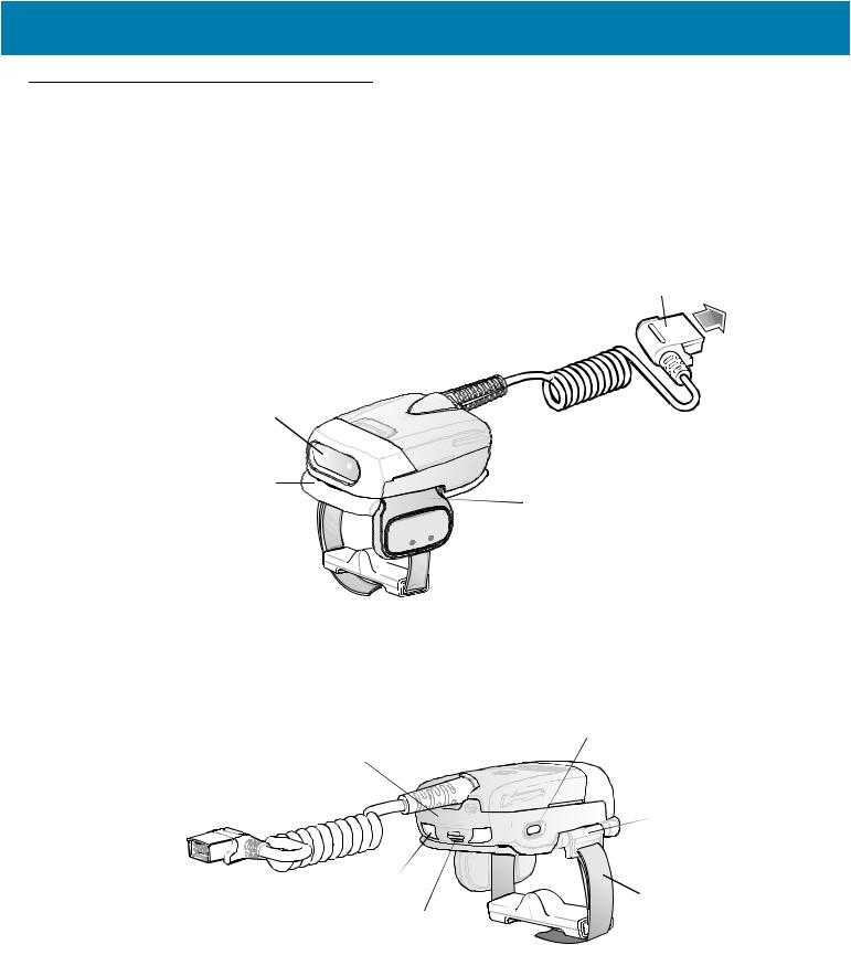
Cordless Configuration Features
Figure 1 RS507 Cordless Configuration Features
Triggered Configuration
 Battery
Imager Window 
 Battery Release Latch
Comfort Pad


 Trigger Swivel Assembly
Finger Strap


Scan Trigger
Asset Control Label |
Restore Key |
|
|
Left Scan LED |
Strap Buckle |
Beeper |
|
Right Scan LED |
Finger Strap |
|
|
|
Triggerless Configuration |
Triggerless Strap Holder
17
Getting Started
Corded Configuration Features
Figure 2 RS507 Corded Configuration Features
|
Interface Cable Connector to WT4XXX |
|
Release Latch |
Imager Window |
|
|
Corded Adapter |
Comfort Pad |
Trigger Swivel Assembly |
|
|
Finger Strap |
Scan Trigger |
|
Restore Key
Asset Control Label
 Strap Buckle
Left Scan LED
 Finger Strap
Beeper
Right Scan LED
18
Getting Started
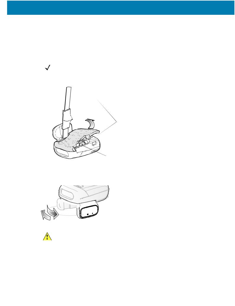
Trigger Swivel Assembly - Change Trigger Position
The Imager is worn on the index and middle fingers, and triggered with the thumb. The Trigger Swivel Assembly of the Imager rotates to provide left-hand or right-hand use.
To change the position of the Trigger:
1.From the bottom of Imager, hold and pull the Comfort Pad off the Imager.
NOTE: When removing the Comfort Pad off the Imager, It is not necessary to remove the Finger Strap from the Trigger Swivel Assembly.
Figure 3 Change Trigger Position - Release Finger Strap from Buckle and Remove Comfort Pad
Finger Strap
Comfort Pad
Trigger 
Swivel
Assembly
Strap Buckle
2.Determine whether the Imager is used on the right or left hand and rotate the Trigger Swivel Assembly.
Figure 4 Change Trigger Swivel Assembly Position


 Trigger Swivel Assembly
 Scan Trigger
CAUTION:The Trigger Swivel Assembly only rotates 180° around the front of the scan assembly. Do not rotate the Trigger Swivel Assembly past the designed stops.
3.Rotate the Trigger Swivel Assembly so that the Scan Trigger is positioned next to the thumb when the Imager is placed on the index and middle fingers.
4.Position the Comfort Pad onto the Imager.
5.Press the Comfort Pad onto the Imager. When properly installed, the Comfort Pad locks into place.
6.Insert the Finger Strap into the Strap Buckle.
19
Getting Started
Getting Started - Cordless Configuration
Charge the Battery
Before using the Imager, charge the battery. The SAC5070 8-Bay Battery Charger supports both standard and extended capacity batteries.
To charge the Imager battery, refer to the SAC5070 8-Bay Battery Charger Quick Reference Guide, p/n 72-115989-01 available at: www.zebra.com/support and search for 'SAC5070'.
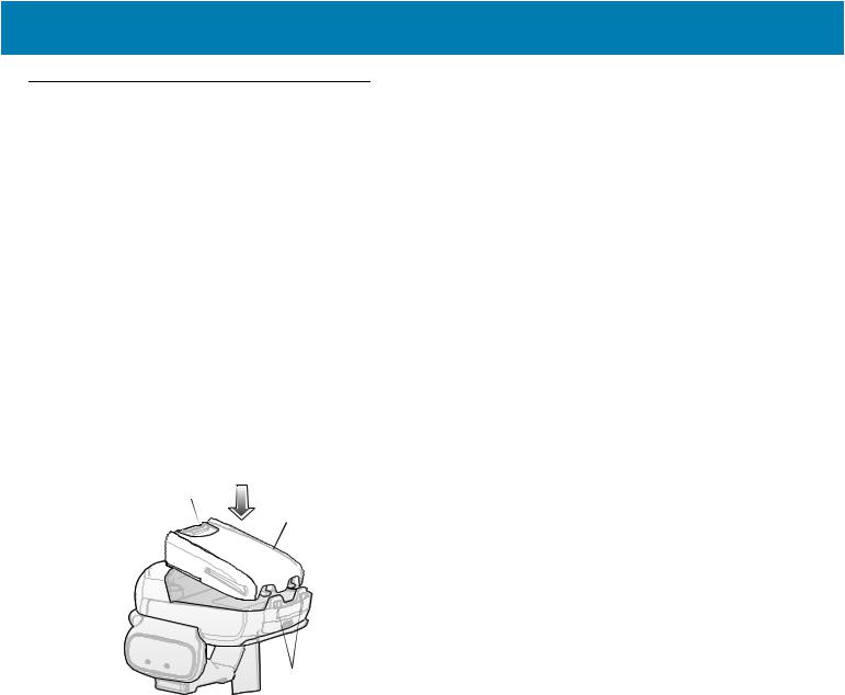
Install the Battery
1.Align the battery on top of the Imager.
2.Push the battery all the way into the Locking Slots of the Imager.
3.Firmly press the battery into the Imager until a “click” is heard ensuring the Battery Release Latch is fully engaged with the Imager.
Figure 5 Install the Battery
Battery Release Latch
Battery
Locking Slots
Remove the Battery
1.Hold the Imager in one hand.
2.Press the Battery Release Latch.
3.Pull up the battery to release it from the Locking Slots of the Imager.
Wearing the Imager
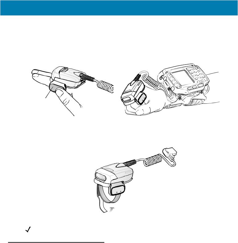
1.Slide the Imager onto the index and middle fingers with the Scan Trigger next to the thumb.
20
Getting Started
Figure 6 Wearing the Imager - Corded Configuration
Scan Trigger
2.Tighten the Finger Strap until it is snug, but not too tight.
CAUTION:To prevent user discomfort, wear the imager snug against the base of the index and middle finger. Do not over tighten.
Figure 7 Wearing the Imager - Cordless Configuration
Finger Strap
NOTE: When using the Imager for the first time, press and release the Scan Trigger to enable the manual triggering mode (this operation disables the default auto triggering mode).
Getting Started - Corded Configuration
In order to start using the Imager you must install the Corded Adapter.
Connect the Corded Adapter
To connect the Corded Adapter:
1.Align the Corded Adapter on top of the Imager.
2.Support the bottom side of the Imager and push the Corded Adapter all the way into the Locking Slots of the Imager.
3.Firmly press the Corded Adapter into the Imager until a click is heard ensuring the Adapter Release Latch is fully engaged with the Imager.
21
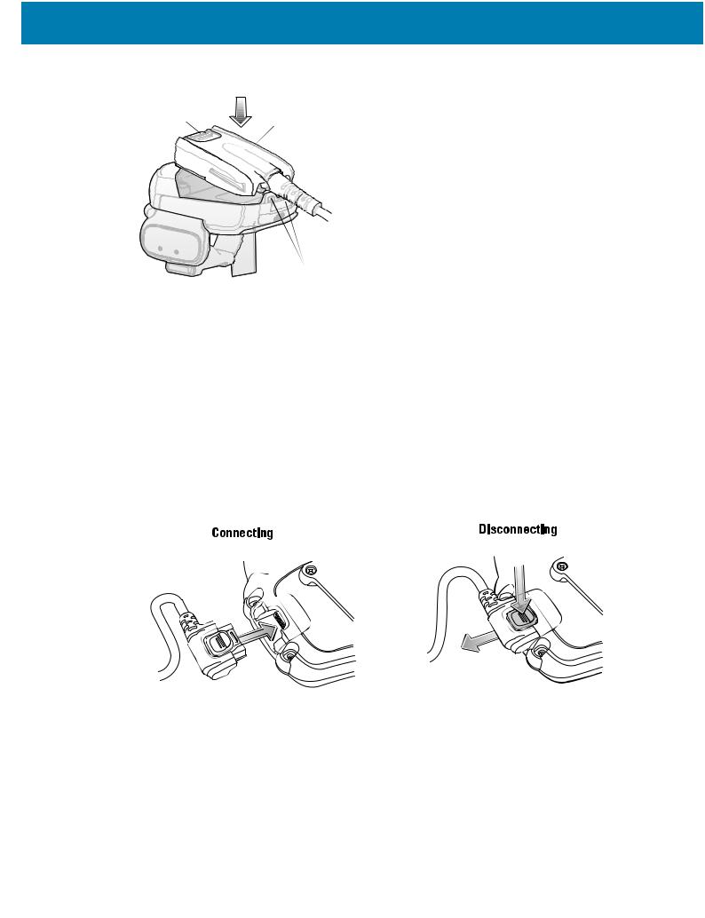
Getting Started
Figure 8 Connect Corded Adapter
Adapter Release Latch |
Corded Adapter |
Locking Slots
Remove the Corded Adapter
To remove the Corded Adapter:
1.Hold the Imager in one hand.
2.Press the Adapter Release Latch.
3.Pull up the Corded Adapter to release it from the Locking Slots of the Imager.
Connect to a WT4XXX Wearable Terminal
The Imager connects to the Wearable Terminal and mounts on the fingers.
Figure 9 Connecting and Disconnecting to a Wearable Terminal
|
WT4XXX Interface Connector |
Interface Cable Connector |
1 |
Disconnect
Button
2
To connect the Imager to the terminal:
1.On the terminal, remove the cover from the WT4XXX Interface Connector.
2.Connect the Interface Cable Connector of the Imager to the WT4XXX Interface Connector.
To disconnect the Imager from the terminal:
1.Press the Disconnect Button on the Interface Cable Connector.
2.Pull the Interface Cable Connector out of the WT4XXX Interface Connector.
22
Getting Started
Wearing the Imager
To wear the Imager:
1.Slide the Imager onto the index and middle fingers with the Scan Trigger next to the thumb (see Figure 10).
Figure 10 Wear the Imager - Corded Adapter
Scan Trigger
2.Tighten the Finger Strap.
Figure 11 Wear the Corded Adapter Imager - Finger Strap
Finger Strap

NOTE: When using the Imager for the first time, press and release the Scan Trigger to enable the manual triggering mode (this operation disables the default auto triggering mode).
Status Indications
The Imager has two Scan LEDs that provide identical indications. The Imager is also equipped with a beeper that issues different beep sequences and patterns to indicate status.
23

Getting Started
Table 2 defines the LED and beep sequences indications that occur during normal operation and bar code scanning.
Table 2 |
Status Indications |
|
|
No. |
LED |
Beep Indication |
Description |
1. |
None |
High/low |
Bluetooth communication is disconnected |
|
|
|
. |
|
|
|
due to: |
|
|
|
• host device is powered off. |
|
|
|
• host device Bluetooth is off. |
|
|
|
• Bluetooth un-pair bar code |
|
|
|
scanned by the RS507. |
|
|
|
• Bluetooth Disconnect bar code |
|
|
|
scanned by the RS507. |
|
|
|
• RS507 is out of Bluetooth range |
|
|
|
with the host device. |
2. |
Short green flashes |
None |
Attempting to connect over Bluetooth. |
3. |
None |
Low/high |
Imager is connected over Bluetooth. |
4. |
None |
High/low/high/low |
Properly decoded scan of Bluetooth |
|
|
|
pairing bar code. |
5. |
None |
Long low/ long high/ |
Bluetooth connection attempt failed. |
|
|
|
If there is no acknowledgment from the |
|
|
|
host device. |
|
|
|
Example: Bluetooth on the host device is |
|
|
|
off. |
6. |
None |
Long low/ long high/ Long low/ |
Bluetooth connection attempt is rejected. |
|
|
long high/ |
When the RS507 tries to connect to the |
|
|
|
host and the host rejects the connection. |
|
|
|
Example: There is already a successful |
|
|
|
Bluetooth connection in the host device |
|
|
|
and it unable to create a new connection. |
7. |
One green flash |
High |
Proper scanning indication. |
8. |
None |
4 long beeps |
No Bluetooth communication after |
|
|
|
re-connection failure. |
9. |
Red flash |
2 short beeps every 15 seconds |
Low battery. |
10. |
Long red flash |
High/low High/low |
Clean Boot was performed successfully. |
|
followed by a green |
|
|
|
flash |
|
|
NOTE: When the Imager is connected by corded configuration, only “Proper scanning indication” and “Clean Boot was perform successfully” status events are indicated.
24

Getting Started
Imager Standby Mode
To save battery power, the Imager goes into Standby when not active.
The Image resumes functionality when:
•Bluetooth data is received from the mobile computer (in cordless configuration)
•Scan trigger is pressed
•Restore key is pressed
•Motion is detected (in cordless configuration)
•Incoming data from mobile computer is sensed (in corded configuration).
Bluetooth Connection
Establish Bluetooth Connection
To establish Bluetooth connection with a mobile computer:
1.Ensure that the Imager is within a range of 10 meters (30 feet) from the mobile computer.
2.Install the battery in the Imager.
3.Launch the Bluetooth Device (BD) address application (see Figure 12) from the mobile computer. Most BD
Address applications display a pairing bar code image on the screen of the mobile computer.
NOTE: To find the BD address application tap the Start button and select Programs > Display_BD_Address or Start > Programs > BT Information and then tap the Generate Local BD Address Barcode button to display the BD address bar code.
25

Getting Started
Figure 12 Icon of Bluetooth Device (BD) Address Application
BluetoothDevice(BD) address icon
on WT4XXXApplication screen
BluetoothDevice(BD) address icon |
Bluetooth Device (BD) address icon on |
on MC909X Demo screen |
Windows Mobile Programs screen |
Bluetooth pairing application for |
BTUI pairing application for WT41N0 |
WT6000 |
4.Scan the pairing bar code on the mobile computer screen (see Figure 13) or a provided pairing label. When scanning, the Imager emits one string of high/low/high/low beeps.
NOTE: To create printed pairing bar code label, refer to Pairing Bar Code Format on page 28.
Figure 13 Pairing Bar Code Example as Shown on the Mobile Computer Screen
26

Getting Started
5.The Scan LED starts flashing green indicating that the Imager is attempting to establish connection with a mobile computer.
NOTE: If the Imager default PIN code is required for establishing connection, enter the following code: "12345". You may also need to set the authentication and encryption to Enabled.
6.When connection is established, the Scan LED turns off and the Imager emits one string of low/high beeps.
The Imager is connected and ready for scanning.
NOTE: When replacing the Imager battery, the Imager memory retains the pairing information of the last paired mobile computer.
Restore Lost Bluetooth Connection
The Imager maintains Bluetooth communication with a mobile computer within a range of 10 meters (30 feet).
When the Imager fails to establish connection or connection is lost during operation, the Imager emits one string of high/low beeps.
To reestablish the Bluetooth connection with a mobile computer:
1.Ensure that the Imager is within a range of 10 meters (30 feet) from the mobile computer.
2.Ensure that the mobile computer is on and “awake” (not in Suspend mode).
3.The Imager automatically attempts reconnecting to the mobile computer for 30 seconds (Scan LED flashes green). If automatic re-connection fails, verify that the Imager is within Bluetooth range and briefly press the Restore Key on the Imager to reconnect.
NOTE: You can also reconnect by scanning a pairing bar code from the mobile computer screen or provided label. When scanning, the Imager emits one string of high/low/high/low beeps.
4.The Scan LED starts flashing green indicating that the Imager is attempting to establish connection with a mobile computer. The Scan LED turns off and the Imager emits one string of low/high beeps indicating that the
Imager is connected and ready for scanning.
Remove Bluetooth Connection
Remove Bluetooth connection to allow the Imager to connect to another mobile computer or to enable the a mobile computer to accept the connection from another Imager.
NOTE: Removing Bluetooth connection is only required if the Imager is configured to auto-connect upon power-up (permanent pairing is enabled) and has to be paired with a different mobile computer.
To remove Bluetooth connection:
1.Scan an un-pairing bar code for disconnecting the Imager from the mobile computer.
Figure 14 Un-pairing Bar Code
2.The Imager emits one string of high/low beeps indicating that Bluetooth communication with the mobile computer is disconnected.
27

Getting Started
Pairing Bar Code Format
In order to pair the Imager with a mobile computer over Bluetooth, a pairing bar code must be created. You can use the Display_BD_Address application on the mobile computer, or create and print a pairing bar code label. To create a pairing bar code label, the Bluetooth address of the mobile computer should be available (refer to the mobile computer user guide).
Pairing bar codes are Code 128, Data Matrix or Aztec symbologies formatted as follows: <Fnc3>Bxxxxxxxxxxxx
Where xxxxxxxxxxxx represents the 12-character Bluetooth address.
Pairing Bar Code Example
If the mobile computer to which the Imager connects has a Bluetooth address of 11:22:33:44:55:66, then the pairing bar code is:
Figure 15 Creating a Pairing Bluetooth Bar Code
Paring Bar Code Content: <Fnc 3> ‘B’ + Bluetooth Address
Scan
The Imager uses digital camera technology to take an image of a bar code and software decoding algorithms are executed to extract the bar code data from the image.
Scan Triggering Modes
Manual Triggering (Triggered models only)
1.Launch a scanning software application on the mobile computer.
2.Position the Imager approximately 22.8 cm (9 inches) from a bar code and press the Scan Trigger. Position the cross hair laser beam to cover the bar code. The Imager takes a digital picture (image) of the bar code and stores it in memory for decoding.
NOTE: After battery is inserted or a corded adaptor is connected (on both sides), the first trigger press disables the auto triggering mode.
3.One green flash of the LEDs is given and a high beep sounds to indicate that the bar code was properly decoded.
NOTE: In some configurations proper decoding of a bar code is indicated by the software application running on the mobile computer.
Auto-triggering (Triggerless models only)
The Imager is provided with auto-triggering capability. In auto-triggering mode, both motion and proximity sensors are used to trigger the Imager when the user intends to scan a bar code.
28
Getting Started
With auto-triggering activated, the Imager automatically scans when motion stops and a bar code is placed within the depth of field of the Imager. The Imager scans the bar code and turns off to conserve power.
To scan a bar code in auto-triggering mode:
1.Position the Imager approximately 22.8 cm (9 inches) from a bar code.
2.Aim at the bar code.
3.The Imager takes a picture (image) of the bar code and stores it in memory for decoding.
4.One green flash of the Scan LEDs and a high beep indicates that a bar code was properly decoded.
NOTE: In some applications, proper detection of a bar code is indicated by a software application running on the mobile computer.
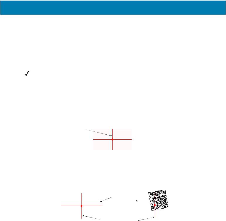
Aiming the Imager
The aiming pattern of the Imager is a cross hair laser beam with bright center dot (see Figure 16). The virtual rectangle made by the cross hair reflects the field of view of the Imager. The aiming pattern is used to position the bar code within the field of view.
Figure 16 Cross Hair Laser Beam
Cross hair laser beam
 Virtualrectanglemadeby thecrosshair laser beam
Enter the symbol in any orientation within the virtual rectangle made by the cross hair laser beam, making use of its omnidirectional reading capability within the entire field of view.
Figure 17 Symbol Scan Orientation
1D Bar Code |
2D Bar Code |
Symbol |
|
@1234@ |
|
Aiming pattern Pattern |
|
The Imager can also read a bar code presented within the aiming pattern but not centered (see the top bar codes on Figure 18). The bar codes marked with X in Figure 18, however, show bar code aiming that may result in no decode.
When using the application on your mobile computer in “Pick List” mode, the Bright Center Dot can be positioned anywhere on the symbol (see Figure 16).The top examples in Figure 18 show acceptable aiming options, while the bottom examples can not be decoded.
29
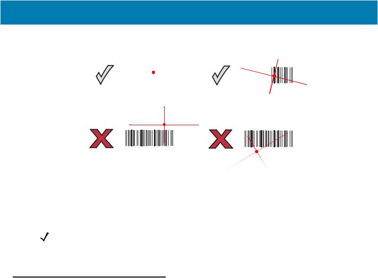
Getting Started
Figure 18 Acceptable Aiming Options
|
|
|
|
|
|
|
|
|
|
|
|
|
|
|
|
|
|
|
|
|
|
|
|
|
|
|
|
|
|
|
|
|
|
|
|
|
|
|
|
|
|
|
|
|
|
|
|
|
|
|
|
|
|
|
|
|
|
|
|
|
|
|
|
|
|
|
|
|
|
|
|
|
|
|
|
|
|
|
|
|
|
|
|
|
|
|
0 1 2 3 4 |
5 |
|
|
|
|
|
|
|
|
|
|
0 1 2 |
||||||||||||||||
|
|
|
|
|
|
|
|
|
|
|
|
|
|
|
|
|
|
|
|
|
|
|
|
|
|
|
|
|
0 1 2 3 4 5
The aiming pattern is smaller when the Imager is closer to the symbol and larger when it is farther from the symbol. Scan symbols with smaller bars or elements (mil size) closer to the Imager and those with larger bars or elements
(mil size) farther from the Imager.
1.Hold the Imager between two and eleven inches from the bar code (depending on the bar code density).
NOTE: When a symbol is under transparent plastic or on a mobile computer screen, it is recommended to use a tilt (pitch) or skew scan angle to minimize reflection.
2.Press the Scan trigger. The aiming pattern illuminates red indicating that the laser is on. One green flash of the Scan LED and a high beep indicates that a bar code was properly decoded.
Customize the Imager
Changing from Triggered to Triggerless Configuration
To change from Triggered to Triggerless configuration:
1.Remove the Comfort Pad (see Comfort Pad Replacement on page 40).
2.Remove the Trigger Swivel Assembly (see Trigger Swivel Assembly Replacement on page 41).
3.Install the Triggerless Strap Holder (see Triggerless Strap Holder Replacement on page 42).
4.Install the Comfort Pad (see Comfort Pad Replacement on page 40).
5.Perform a cold boot (see Cold Boot on page 31).
Changing Triggerless to Triggered Configuration
To change from Triggerless to Triggered configuration:
1.Remove the Comfort Pad (see Comfort Pad Replacement on page 40).
2.Remove the Triggerless Strap Holder (see Triggerless Strap Holder Replacement on page 42).
3.Install the Trigger Swivel Assembly (see Trigger Swivel Assembly Replacement on page 41).
4.Install the Comfort Pad (see Comfort Pad Replacement on page 40).
5.Perform a cold boot (see Cold Boot on page 31).
30
Loading...