


RIFLESCOPE
PHOTON 3.5x42 / 5x42
Riflescope Photon 3.5x42 / 5x42................................................................................................ |
1-10 |
|
|
Viseur Photon 3.5x42 / 5x42....................................................................................................... |
11-20 |
|
|
|
|
Zielfernrohr Photon 3.5x42 / 5x42............................................................................................... |
21-30 |
|
|
|
|
Visor Photon 3.5x42 / 5x42 ......................................................................................................... |
31-40 |
|
|
|
ITALIANO |
Cannochiale Photon 3.5x42 / 5x42 ............................................................................................ |
41-50 |
|
|
|
|
Прицел Photon 3.5x42 / 5x42 .................................................................................................... |
51-60 |
|
|
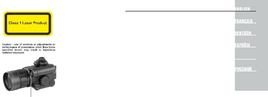
Laser aperture |
v.0313 |

SKU |
26321 |
26323 |
26324 |
26326 |
|
ENGLISH |
|
|
|||||
Model |
Photon 5x42 |
Photon-V 5x42 |
Photon 3.5x42 |
Photon-V 3.5x42 |
Max. detection range of an |
|
Optical characteristics |
|
|
|
|
* |
|
|
|
|
|
|
object measuring 1.7x0.5 m |
|
Magnification, x |
5 |
5 |
3.5 |
3.5 |
|
in natural night conditions |
Objective lens diameter, mm |
42 |
42 |
42 |
42 |
|
(0.05 lux, quarter moon). |
** |
Depending on the region of |
|||||
Field of view, degree / m |
4 / 7 |
4 / 7 |
6.5 / 11 |
6.5 / 11 |
|
sale. |
Exit pupil, mm |
8 |
8 |
8 |
8 |
|
|
Eye relief, mm |
82 |
82 |
82 |
82 |
|
|
Click value, MOA (mm) |
1/4 (7) |
1/4 (7) |
1/4 (7) |
1/4 (7) |
|
|
Close-up distance, m |
1 |
1 |
1 |
1 |
|
|
Eyepiece dioptre adjustment, D |
-2 / +2.5 |
-2 / +2.5 |
-2 / +2.5 |
-2 / +2.5 |
|
|
Max. detection range (built-in IR illuminator on), m/yds* |
190 / 208 |
150 / 164 |
160 / 175 |
120 / 131 |
|
|
Resolution, lines/mm |
36 |
36 |
36 |
36 |
|
|
Electronic specifications |
|
|
|
|
|
|
Type of array |
CMOS / 1/4" |
CMOS / 1/4" |
CMOS / 1/3" |
CMOS / 1/3" |
|
|
Camera resolution, pixel |
500x582 |
500x582 |
768x576 |
768x576 |
|
|
Built-in IR Illuminator |
Laser |
Laser |
Laser |
Laser |
|
|
Wavelength, nm |
780 |
915 |
780 |
915 |
|
|
Equivalent power, mW |
150 |
150 |
150 |
150 |
|
|
Safety class for laser equipment acc. to IEC 60825-1:2007 |
1 |
1 |
1 |
1 |
|
|
Output power for laser radiation, not more than |
13 mW |
20 mW |
13 mW |
20 mW |
|
|
Operational characteristics |
|
|
|
|
|
|
Tube diameter, mm |
30 |
30 |
30 |
30 |
|
|
Power supply (Battery type): riflescope/reticle |
3V (2xAA) / 3V (CR2032) |
3V (2xAA) / 3V (CR2032) |
|
|
||
External power supply / Power consumption |
8.4-15V / 0.9W |
8.4-15V / 0.9W |
8.4-15V / 0.9W |
8.4-15V / 0.9W |
|
|
Operation time with one set of recharg. batt. (IR off/on), hour |
4 / 3 |
4 / 3 |
4 / 3 |
4 / 3 |
|
|
Degree of protection, IP code (IEC 60529) |
IPX4 |
IPX4 |
IPX4 |
IPX4 |
|
|
Video output |
CCIR / EIA** |
CCIR / EIA** |
CCIR / EIA** |
CCIR / EIA** |
|
|
Max. shock resistance |
5000 Joules |
5000 Joules |
5000 Joules |
5000 Joules |
|
|
Operating temperature |
-10 ºC … +50 ºC / +14 ºF... +122 ºF |
-10 ºC … +50 ºC / +14 ºF... +122 ºF |
|
|
||
Dimensions, mm / inch |
350x77x80 / 13.7x2.8x3.1 |
350x77x80 / 13.7x2.8x3.1 |
|
|
||
Approx. weight, kg / oz |
0.9 / 31.7 |
0.9 / 31.7 |
0.9 / 31.7 |
0.9 / 31.7 |
|
|
1
PACKAGE CONTENTS
Riflescope Photon
Carrying case
User manual
Video cable
Cleaning cloth
Warranty card
For improvement purposes, design of this product is subject to change.
DESCRIPTION
The riflescope Photon is an original combination of a digital riflescope and daylight sight. The reticle has illuminated dot with adjustable brightness. The riflescopes are equipped with 780/915 nm built-in eyesafe laser IR Illuminators. The 915 nm IR operates in the invisible range which allows covert observation. The riflescopes can be mounted using regular mounting brackets for day sights. The riflescope is designed for observation in the twilight or in the nighttime but due to the use of CMOS array, the unit can be used in the day too. The lens cap has a light filter which reduces image brightness. The riflescopes Photon is designed for hunting, sports shooting, security, general observation.
FEATURES
3.5x/5x optical magnification 82 mm eye relief
Built-in eyesafe laser IR Illuminator (780 or 915 nm) Ability to use any standard mounts for daylight sights Reticle with illuminated red dot
Contrast image
Adjustable image brightness External power supply
Video output – ability to use external recording equipment Lightweight and compact
2

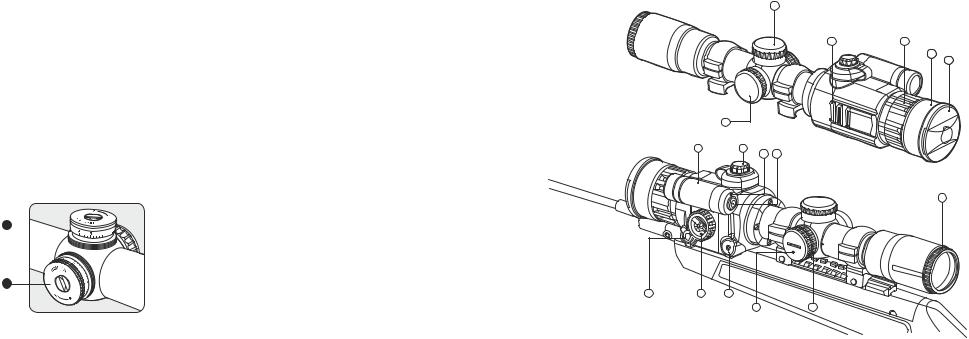
 COMPONENTS AND CONTROL ELEMENTS
1.Built-in laser IR Illuminator
2.Battery compartment knob
3.LED indicator
4.“IR” button
5.Eyepiece adjustment ring
6.Cover of reticle illumination battery compartment
7.Reticle brightness control knob
8.External power supply jack
9.Unit on/off wheel/Display brightness control wheel
10.Video output
11.Windage adjustment turret
12.Elevation adjustment turret
13.Additional Weaver rail
14.Objective lens
15.Lens focus knob
16.Lens cap
12 
|
3 |
|
4 |
|
8 |
11 |
9 |
|
|
|
10 |
12
13 |
15 |
14
165
11
1 |
2 |
3 4
5
V

DC
10 9 8
6 |
7 |
3 |
4 |
BATTERY INSTALLATION |
- |
+ |
Turn the knob (2) of the battery compartment |
/1.5V |
/1.5V |
cover 90° counterclockwise. |
AA |
AA |
Remove the cover by raising it by its lug. |
+ |
- |
Slide in two АА batteries so that the “+” and “-” |
|
|
match the polarity on the inner side of the cover; |
|
|
rechargeable AA batteries may be used. |
|
|
Close the cover of the battery compartment cover |
|
|
and turn the knob (2) of the cover 90° clockwise. |
|
|
Note: to ensure long and reliable operation it is |
|
|
recommended that you use quality rechargeable |
|
|
batteries with a capacity of at least 2500 mAh. |
|
|
Please do not use batteries of different types or |
|
|
batteries with various charge levels. |
|
|
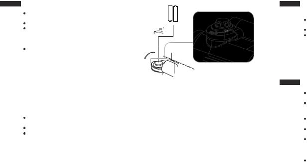
EXTERNAL POWER SUPPLY |
|
|
The riflescope can be powered with an external DC power supply (2.1mm pin) with stabilised voltage ranging from 8.4V to 15V or a 12V vehicle socket.
External power supply (AC/DC) is to be connected to “Power” (8) jack located on the right side of the device.
Note: the central pin of the power supply that you connect to the “power” jack of the riflescope, must have marking “+”.
The power supply may have marking - 
 +
+
Connection of an external power supply automatically cuts off power supply from batteries. External power supply DOES NOT charge the batteries in the riflescope!
Attention! We suggest that you use battery packs EPS3 or EPS5 ensuring up to 40 hours of continuous operation.
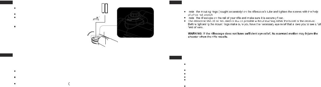
MOUNTING THE RIFLESCOPE
To ensure precise shooting the sight should be correctly mounted on a rifle. Please follow these steps:
STARTING THE SCOPE AND IMAGE SETUP
Remove the cap (16) from the lens (14). The cap is outfitted with a light filter which reduces image brightness in the daylight.
Turn on the riflescope by turning the wheel (9) clockwise until it clicks. A green LED indicator (3) will light up. Important! When the indicator changes its colour to red, please replace the batteries.
Rotate the eyepiece adjustment ring (5) to see on the display a sharp image of the reticle.
Rotate the wheel (9) to adjust brightness: clockwise – to increase brightness; counterclockwise – to decrease brightness.
To switch on the illuminated reticle, set the knob (7) against corresponding mark on the housing showing one of the illumination levels (there are 11 levels). Reticle illumination is powered by a single CR2032 Lithium battery. To replace the battery, unscrew the cover (6) of the knob counterclockwise and insert a new battery with “+” facing upwards. Screw the cover.
5 |
6 |
Aim at a target 20-30 meters away.
Rotate the lens focus knob (15) to achieve quality image.
After this adjustment no further dioptre adjustment should be required, regardless of distance or other factors. Adjust the image with the lens focus knob (15) only.
In low light conditions or in complete darkness turn on the built-in IR Illuminator (1) by pushing the “IR” (4) button. The built-in IR is not focusable.
To turn off the scope, rotate the wheel (9) clockwise until it clicks.
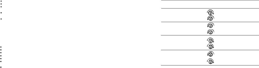
 ZEROING
Bore sighting is a preliminary procedure to achieve proper alignment of the sight with the rifle's bore.
Mount the rifle with the riflescope installed on a bench rest. Aim at a target 100 meters away.
Turn on the riflescope, adjust display brightness and achieve a sharp image of the reticle. Rotate the lens focus knob (15) to achieve a sharp image of the target.
Take aim and shoot at the centre of the target.
If the point of impact did not match with the aiming point, unscrew the caps of windage (11)/elevation (12) turrets and use the turrets to line up the centre of the reticle and the point of impact.
Take two shots. If required, re-adjust the reticle.
Turn direction |
Point of impact |
Elevation adjustment (12) |
Left up |
Windage adjustment (11) |
|
Elevation adjustment (12) |
Left down |
Windage adjustment (11) |
|
Elevation adjustment (12) |
Right up |
Windage adjustment (11) |
|
Elevation adjustment (12) |
Right down |
Windage adjustment (11) |
|
ATTENTION!
Each click of the Adjustment Scale Ring will change bullet impact by 1/4 MOA (Minute of Angle) which equates to 7 mm at 100 meters.
7 |
8 |

 VIDEO OUT JACK
“Video out” jack (10) is designed to connect external recording devices and to transmit video signal to monitors, TV sets etc.
Connect an external signal source to the “Video out” jack (10) with the supplied video cable. Turn on the scope – an image will show up on an external device.
 ACCESSORIES
With the help of the an additional Weaver rail (13) you can attach accessories like:
Accessory Pulsar-805/Pulsar-940 IR Flashlight (#79071/79076);
Laser IR Illuminator Pulsar L-808S/L-915 (#79072/79075);
External power supply EPS3/EPS5 (#79111/79112);
Video recorder CVR640 (#17044) etc.
 MAINTENANCE AND STORAGE
The riflescope features IPX4 degree of protection (protected against splash water) but cannot be submerged in water.
Attempts to disassemble or repair the scope will void the warranty!
Clean the scope's optical surfaces only if necessary, and use caution. First, remove (by blowing with a blower brush or canned air) any dust or sand particles. Then proceed to clean by using camera/lens cleaning equipment approved for use with multicoated lenses. Do not pour the solution directly onto the lens!
The riflescope can be used in operating temperatures ranging from -10 °C... +50 °C. However, if it has been brought indoors from cold temperatures, do not turn it on for 2 to 3 hours. This will prevent external optical surfaces from fogging.
Always store the unit in its carrying case in a dry, well-ventilated space. For prolonged storage, remove the batteries.
TROUBLESHOOTING
Listed below are some potential problems that may occur when using the scope. Carry out the recommended checks and troubleshooting steps in the order listed. Please note that the table does not list all of the possible problems. If the problem experienced with the scope is not listed, or if the suggested action meant to correct it does not resolve the problem, please contact the manufacturer.
problem |
possible cause(s) |
сorrective action |
The riflescope will not turn on. |
Batteries have been wrongly installed. |
Reinstall the batteries with the correct polarity orientation. |
|
Oxidized contact points in the battery |
Clean the battery compartment, focusing on the contacts. |
|
compartment due to “leaky” batteries or |
|
|
contact points becoming exposed |
|
|
to a chemically-reactive solution. |
|
|
The batteries are empty. |
Install fresh batteries. |
The image is too dark. |
Low brightness settings. |
Adjust image brightness by rotating the wheel (9). |
|
Make sure the lenses are not misted |
Clean the lenses with a cloth wetted in spirit. |
|
or dirty. |
|
Poor image quality. |
Check that the eyepiece and lens are |
Adjust in accordance with the user manual. |
|
adjusted in accordance with the user |
|
|
manual. |
|
There are several light or black dots |
Presence of dots is caused by CMOS chip production technology and is not a defect. |
|
(pixels) on the display of the device. |
|
|
|
|
|
Barely visible texture which does not impact |
This is normal for eye safe laser illuminators. |
|
detection range and efficiency of observation |
|
|
can be noticed on the display after the built-in |
|
|
laser IR Illuminator is activated. |
|
|
Peculiarities of CMOS array
CMOS arrays employed in Yukon digital night vision devices, feature high quality. However certain pixels (or groups of pixels) with increased luminosity (lighter or darker) are allowed. These defects can be seen when conducting observation not only in the nighttime but in the day time too, especially if SumLight function is active. Presence of light and dark pixels and other minor defects of a CMOS array (up to 4%) are acceptable in accordance with regulations of the producer. Visibility on the screen of light pixels also depends on the type of CMOS array,heating temperature during operation.
9 |
10 |

SKU |
26321 |
26323 |
26324 |
26326 |
Modele |
Photon 5x42 |
Photon-V 5x42 |
Photon 3.5x42 |
Photon-V 3.5x42 |
Caracteristiques optiques: |
|
|
|
|
Grossissment optique, fois |
5 |
5 |
3,5 |
3,5 |
L'objectif, mm |
42 |
42 |
42 |
42 |
Champ visuel, degré d'angle / m @100m |
4 / 7 |
4 / 7 |
6,5 / 11 |
6,5 / 11 |
Diamètre de la pupille de sortie, mm |
8 |
8 |
8 |
8 |
Degagement oculaire, mm |
82 |
82 |
82 |
82 |
Correction du point d’impact par clic, МОА (mm) |
1/4 (7) |
1/4 (7) |
1/4 (7) |
1/4 (7) |
Distance de mise au point minimale, m |
1 |
1 |
1 |
1 |
Ajustement dioptrique de l'oculaire, dioptries |
-2 / +2,5 |
-2 / +2,5 |
-2 / +2,5 |
-2 / +2,5 |
Distance maximum de la detection avec IR intégrée, m |
190 |
150 |
160 |
120 |
La résolution, lignes/mm |
36 |
36 |
36 |
36 |
Caracteristiques électroniques
* Distance max. de la detection du object avec dimensions 1,7x0,5 m à l ' é c l a i r a g e n o c t u r n e naturel 0,05 lux (un quart de la lune).
** Selon le lieu de vente.
Type de la matrice |
CMOS / 1/4" |
CMOS / 1/4" |
CMOS / 1/3" |
CMOS / 1/3" |
La résolution de la camera, pixel |
500x582 |
500x582 |
768x576 |
768x576 |
La torche IR integree |
a laser |
a laser |
a laser |
a laser |
Longueur d'onde, nm |
780 |
915 |
780 |
915 |
Puissance équivalente (plage de variation), mW |
150 |
150 |
150 |
150 |
Classe de dispositifs laser selon IEC 60825-1:2007 |
|
|
|
|
(sécurité de fonctionnement des dispositifs laser) |
1 |
1 |
1 |
1 |
Puissance de sortie pour le rayonnement laser, pas plus de |
13 mW |
20 mW |
13 mW |
20mW |
Caracteristiques fonctionnelles: |
30 |
30 |
30 |
30 |
Diametre du tube, mm |
||||
Tension de travail, V (Batteries) - viseur/réticule |
3V (2xAA)/3V (CR2032) |
3V (2xAA)/3V (CR2032) |
||
Alimentation exterieure / Énergie absorbee |
8,4-15V / 0,9W |
8,4-15V / 0,9W |
8,4-15V / 0,9W |
8,4-15V / 0,9W |
Temps de fonctionnement avec un kit de batteries |
4 / 3 |
4 / 3 |
4 / 3 |
4 / 3 |
(infrarouge intégré arrêt/marche), heure |
||||
Classe de protection, code IP (IEC 60529) |
IPX4 |
IPX4 |
IPX4 |
IPX4 |
Modele du signal |
CCIR/EIA** |
CCIR/EIA** |
CCIR/EIA** |
CCIR/EIA** |
Resistance au choc, max |
5000 J |
5000 J |
5000 J |
5000 J |
Temperature d'utilisation |
-10 ºC … +50 ºC |
-10 ºC … +50 ºC |
-10 ºC … +50 ºC |
-10 ºC … +50 ºC |
Dimensions, mm |
350x77x80 |
350x77x80 |
350x77x80 |
350x77x80 |
Poids (sans le montage), kg |
0,9 |
0,9 |
0,9 |
0,9 |
11
CONTENU DE L'EMBALLAGE
Viseur Photon
Etui de transport
Manuel d'utilisation
Cable video
Chiffonette
Carte de garantie
Le design de ce produit pourrait-être amené à changer, afin d'améliorer son utilisation.
DESCRIPTION
Le viseur Photon représente une combinaison originale d'un dispositif numérique et d'un viseur optique fonctionnant aux conditions d'éclairage naturel. Le dispositif est destiné à être utilisé pour l'observation effectuée au crépuscule ou pendant la nuit, grâce à sa matrice photosensible on peut l'utiliser aussi aux conditions d'éclairage naturel. Pour le fonctionnement aux conditions de la nuit le dispositif est muni soit d'un éclaireur à laser incorporé, ce qui permet d'améliorer sensiblement la qualité de l'image et d'augmenter la distance de détection.
Les viseurs Photon sont destinés à être employé pour la chasse, le tir sportif, la garde, l'observation visuelle générale.
CARACTERISTIQUES SPECIFIQUES
Agrandissement optique 3,5x/5x
Eloignement de la pupille de sortie de 82 mm
Torche infrarouge incorporé 780 ou 915 nm
Possibilité d'utiliser tous les éléments de fixation standard pour les lunette de visée
Réticule au point rouge éclairé
Image contrastée
Réglage de la brillance de l'image
Alimentation externe
Sortie vidéo rendant possible l'enregistrement vidéo sur d'autres dispositifs
Poids et encombrement peu importants
12
 ELEMENTS DU VISEUR ET ORGANES DE COMMANDE
1.Torche infrarouge à laser incorporé
2.La manivelle du compartiment de batterie
3.Indicateur à LED
4.Bouton “IR”
5.Anneau d'ajustage dioptrique de l'oculaire
6.Couvercle du compartiment de batterie d'éclairage du repère de visée
7.Poignee de réglage de la luminosite du réticule
8.Connecteur d'alimentation externe
9.Anneau d'enclenchement de dispositif/de réglage de brillance de l'ecran
10.Sortie vidéo
11.Disque de réglage (vers la droite/vers la gauche)
12.Disque de réglage (vers le haut/vers le bas)
13.Rail Weaver supplémantaire
14.L'objectif
15.Anneau de focalisation interne de l'objectif
16.Couvercle d'objectif
12 
|
3 |
|
4 |
|
8 |
11 |
9 |
|
|
|
10 |
12
13 |
15 |
14
165
11
1 |
2 |
3 4
5
V

DC
10 9 8
6 |
7 |
13 |
14 |
INSTALLATION DES PILES |
- |
+ |
Tourner la manivelle du couvercle (2) du compartiment |
/1.5V |
/1.5V |
à piles, à 90° dans le sens inverse des aiguilles d'une montre. |
AA |
AA |
Installez les piles selon le marquage sur le couvercle. |
+ |
- |
Glisser à l'intérieur deux piles AA, en faisant en sorte |
|
|
que le “+” et le “-“ correspondent à la polarité indiquée à |
|
|
l'intérieur du couvercle; les piles AA rechargeables sont |
|
|
tolérées. |
|
|
Fermer le couvercle du compartiment à piles |
|
|
et tourner l'écrou du couvercle à 90° dans le |
|
|
sens des aiguilles d'une montre. |
|
|
Note: pour assurer un fonctionnement fiable et durable |
|
|
il est conseillé que vous utilisez des piles rechargeables |
|
|
de qualité avec une capacité d'au moins 2500 mAh. Veuillez ne pas utiliser de piles de différents types ou des piles avec des niveaux différents de charge.
 ALIMENTATION EXTERIEURE
L'appareil peut fonctionner à l'aide d'une source extérieure d'alimentation (prise mâle 2,1mm) ou d'un réseau d'automobile. La plage de la tension d'entrée varie de 8,4V à 15V.
Une source extérieure d'alimentation (AC/DC) doit être raccordée au port “Power” (8) qui se trouve sur le revers du panneau droit de l'appareil.
Attention! Dans la cheville de contact de l'alimentation raccordée au viseur le contact central doit être “+”. Le marquage possible sur la cheville de contact ou sur la source d'alimentation - 
 +
+
Lors du raccordement d'une source extérieure d'alimentation (sur le panneau d'affichage apparaît une icône - voir la figure) l'alimentation par piles est coupée. Pendant le fonctionnement à l'aide d'une source extérieure d'alimentation la charge des accumulateurs ne se produit pas!
Remarque: veuillez utiliser l'alimentateur externe EPS3 ou EPS5, qui permet d'assurer le fonctionnement autonome d'une durée jusqu'a 40 heures.
MONTAGE DU VISEUR SUR LE FUSIL
Veillez à ce que le viseur soit monté sur le fusil correctement, afin d'assurer la précision du tir.
Mettez en place les bagues de fixation (non fournies avec le dispositif) sur le tube de viseur et vissez les vis à l'aide d'une clé à six pans.
Montez le viseur sur la barette de visée de votre fusil et rassurez-vous que sa fixation est fiable. Mettez le viseur le plus bas possible, en évitant son contact avec le tube ou avec la boîte de culasse.
Avant de bloquer les bagues de fixation, rassurez-vous que le viseur assure l'éloignement nécessaire de la pupille de sortie et permet de voir le champs de vue total.
ATTENTION! Le viseur peut causer une trauma à l'utilisateur au moment de tir, si l'éloignement de la pupille de sortie n'est pas suffisant.
AVERTISSEMENT: utiliser des éléments de fixation et des bagues de bonne qualité qui ne sont prévues que pour le type de votre fusil.
ENCLENCHEMENT ET AJUSTAGE DE L'IMAGE
Retirez le couvercle (16) de l'objectif (14). Le couvercle filtre de lumiere integre permet de reduire la luminosite de l'image.
Faites fonctionner le viseur, pour faire ceci tournez l'anneau (9) dans le sens horaire jusqu'à ce que vous n'entendiez un clic. Alors l'indicateur de couleur verte (3) s'allume.
ATTENTION! Si la couleur de l'indicateur change en couleur rouge, remplacez les piles!
Réglez l'image nette du repère de visée sur l'afficheur, moyennant la rotation de l'anneau d'ajustage dioptrique de l'oculaire (5).
Réglez la brillance de l'image par rotation de l'anneau (9): en sens horaire – pour augmenter le niveau de brillance, dans le sens contraire – pour le réduire.
Pour pouvoir enclencher le point lumineux du réticule, il faut mettre la manivelle (7) à la valeur voulue de luminescence (11 niveaux de luminescence au total) contre le marquage sur le corps de viseur. Une seule pile de type CR2032 est suffisante pour l'éclairage de repère. Pour changer la pile: dévissez le couvercle sur la manivelle (6) dans le sens anti-horaire et insérer la nouvelle pile, le contact “+” étant vers l'extérieur.
Vissez le couvercle.
15 |
16 |
 Loading...