


 Loading...
Operating manual
IQ SENSOR NET
MIQ/CR3; DIQ/CR3
Power
O |
K |
! |
|
IQ SENSOR NET combi output module
ba76032e01 01/2012

MIQ/CR3; DIQ/CR3
Note
For the most recent version of the manual, please visit www.ysi.com.
Contact YSI
1725 Brannum Lane
Yellow Springs, OH 45387 USA Tel: +1 937-767-7241 800-765-4974
Email: environmental@ysi.com Internet: www.ysi.com
Copyright © 2012 Xylem Inc.
2 |
ba76032e01 |
01/2012 |

MIQ/CR3; DIQ/CR3 |
List of contents |
|
|
MIQ/CR3; DIQ/CR3 - List of contents
1 |
Overview . . . . . . . . . . . . . . . . . . . . . . . . . . . . . . . . . . . . |
1-1 |
|
|
1.1 |
How to use this component operating manual . . . . . . . . |
1-1 |
|
1.2 |
Features of the combi output module . . . . . . . . . . . . . . . |
1-2 |
2 |
Safety instructions . . . . . . . . . . . . . . . . . . . . . . . . . . . . |
2-1 |
|
|
2.1 |
Authorized use . . . . . . . . . . . . . . . . . . . . . . . . . . . . . . . . |
2-2 |
|
2.2 |
General safety instructions . . . . . . . . . . . . . . . . . . . . . . . |
2-2 |
3 |
Installation . . . . . . . . . . . . . . . . . . . . . . . . . . . . . . . . . . |
3-1 |
|
|
3.1 |
Scope of delivery . . . . . . . . . . . . . . . . . . . . . . . . . . . . . . |
3-1 |
|
3.2 |
Installation in the IQ SENSOR NET . . . . . . . . . . . . . . . . . |
3-1 |
|
|
3.2.1 Software requirements of the MIQ/CR3 and |
|
|
|
IQ SENSOR NET . . . . . . . . . . . . . . . . . . . . . . . . . |
3-1 |
|
3.3 |
Electrical connections: General instructions . . . . . . . . . |
3-2 |
|
3.4 |
Connections to the relay and current outputs . . . . . . . . |
3-4 |
4 Settings . . . . . . . . . . . . . . . . . . . . . . . . . . . . . . . . . . . . . 4-1
4.1 |
Basic information on relay functions . . . . . . . . . . . . . . |
. 4-2 |
|
|
4.1.1 |
Monitoring . . . . . . . . . . . . . . . . . . . . . . . . . . . . |
. 4-2 |
|
4.1.2 |
Limit indicator . . . . . . . . . . . . . . . . . . . . . . . . . |
. 4-3 |
|
4.1.3 |
Proportional output . . . . . . . . . . . . . . . . . . . . . |
. 4-5 |
4.2 |
Entering / editing the name of an output . . . . . . . . . . . |
4-12 |
|
4.3 |
Linking the output with a sensor . . . . . . . . . . . . . . . . . . |
4-13 |
|
4.4 |
Deleting a link with an output . . . . . . . . . . . . . . . . . . . . |
4-14 |
|
4.5 |
Setting the relay outputs . . . . . . . . . . . . . . . . . . . . . . . |
4-15 |
|
|
4.5.1 |
Relay action . . . . . . . . . . . . . . . . . . . . . . . . . . |
4-16 |
|
4.5.2 |
System monitoring . . . . . . . . . . . . . . . . . . . . . |
4-17 |
|
4.5.3 |
Sensor monitoring . . . . . . . . . . . . . . . . . . . . . . |
4-18 |
|
4.5.4 |
Limit indicator . . . . . . . . . . . . . . . . . . . . . . . . . |
4-19 |
|
4.5.5 |
Frequency controller . . . . . . . . . . . . . . . . . . . . |
4-21 |
4.5.6Pulse-width contr. . . . . . . . . . . . . . . . . . . . . . . 4-22
4.5.7 Cleaning . . . . . . . . . . . . . . . . . . . . . . . . . . . . . 4-23 4.5.8 Sensor-controlled . . . . . . . . . . . . . . . . . . . . . . 4-27 4.5.9 Manual control . . . . . . . . . . . . . . . . . . . . . . . . . 4-28 4.5.10 Alarm contact . . . . . . . . . . . . . . . . . . . . . . . . . 4-28 4.6 Setting of current outputs . . . . . . . . . . . . . . . . . . . . . . . 4-29 4.6.1 Recorder . . . . . . . . . . . . . . . . . . . . . . . . . . . . . 4-30 4.6.2 PID controller . . . . . . . . . . . . . . . . . . . . . . . . . 4-32 4.6.3 Fixed current value . . . . . . . . . . . . . . . . . . . . . 4-37
ba76032e01 |
01/2012 |
0 - 1 |

List of contents |
MIQ/CR3; DIQ/CR3 |
|
|
4.7 Checking the status of the outputs . . . . . . . . . . . . . . . .4-38
4.8 Behavior of linked outputs . . . . . . . . . . . . . . . . . . . . . . |
4-39 |
|
4.8.1 |
Behavior in case of error . . . . . . . . . . . . . . . . . |
4-39 |
4.8.2 |
Behavior in non-operative condition . . . . . . . . |
4-40 |
4.9 Maintenance condition of sensors . . . . . . . . . . . . . . . .4-41
4.9.1Switching on the maintenance condition . . . . .4-42
4.9.2Switching off the maintenance condition . . . . .4-42
5 Maintenance and cleaning . . . . . . . . . . . . . . . . . . . . . 5-1
5.1 Maintenance . . . . . . . . . . . . . . . . . . . . . . . . . . . . . . . . . .5-1 5.2 Cleaning . . . . . . . . . . . . . . . . . . . . . . . . . . . . . . . . . . . . .5-1
6 Technical data . . . . . . . . . . . . . . . . . . . . . . . . . . . . . . . 6-1 7 Contact Information . . . . . . . . . . . . . . . . . . . . . . . . . . . 7-1
7.1 Ordering & Technical Support . . . . . . . . . . . . . . . . . . . . |
7-1 |
7.2 Service Information . . . . . . . . . . . . . . . . . . . . . . . . . . . . .7-1
8 Indexes . . . . . . . . . . . . . . . . . . . . . . . . . . . . . . . . . . . . . 8-1
8.1 Explanation of the messages . . . . . . . . . . . . . . . . . . . . .8-1 8.1.1 Error messages . . . . . . . . . . . . . . . . . . . . . . . . .8-1 8.1.2 Info messages . . . . . . . . . . . . . . . . . . . . . . . . . .8-1
0 - 2 |
ba76032e01 |
01/2012 |
MIQ/CR3; DIQ/CR3 |
Overview |
|
|
Structure of the
IQ SENSOR NET
operating manual
1 Overview
1.1How to use this component operating manual
IQ Sensor Net Operating Manual |
||
|
|
System |
|
Operating |
|
|
|
Manual |
|
(Ring Binder) |
|
IQ Sensor |
MIQ Module |
MIQ Terminal |
Operating |
Operating |
Operating |
Manual |
Manual |
Manual |
Component Operating Manuals |
||
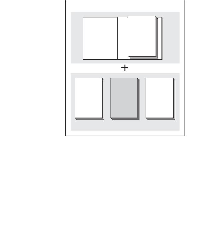
Fig. 1-1 Structure of the IQ SENSOR NET operating manual
The IQ SENSOR NET operating manual has a modular structure like the IQ SENSOR NET itself. It consists of a system operating manual and the operating manuals of all the components used.
Please file this component operating manual into the ring binder of the system operating manual.
ba76032e01 |
01/2012 |
1 - 1 |

Overview |
MIQ/CR3; DIQ/CR3 |
|
|
1.2Features of the combi output module
General characteristics The combi output module has three current outputs and three relay outputs. You can link current outputs and relay outputs to sensors. The linked current outputs and relay outputs can, for example, be used to monitor sensors or to output measurement data. Unlinked relay outputs can be used for general monitoring functions.
With the standard MIQ module housing, the combi output module has the same characteristics as all MIQ modules regarding stability, leakproofness and weather resistance. It also provides the same wide variety of installation options (stacked mounting, canopy mounting, tophat rail mounting, etc.).
Instrument types The MIQ/CR3 and DIQ/CR3 combi output modules differ in their compatibility with the individual IQ SENSOR NET system families.
System |
Compatible combi output module |
|
|
2020 XT |
MIQ/CR3 |
|
|
182 |
DIQ/CR3 |
|
|
Terminal strip The combi output module has the following electrical connections on the terminal strip inside the housing:
3 x relay contact
3 x current output
2 x SENSORNET connection
1 - 2 |
ba76032e01 |
01/2012 |

MIQ/CR3; DIQ/CR3 |
Safety instructions |
|
|
2 Safety instructions
This operating manual contains special instructions that must be followed during the installation of the combi output module. Thus, it is essential for the operator to read this component operating manual before carrying out any work with the system. In addition to this manual, the SAFETY chapter of the IQ SENSOR NET system operating manual must be followed.
Always keep this component operating manual together with the system operating manual and all other component operating manuals in the vicinity of the IQ SENSOR NET system.
Special user External circuits carrying mains voltage must only be connected to the qualifications relay contacts by a qualified electrician.
General safety Safety instructions in this operating manual are indicated by the instructions warning symbol (triangle) in the left column. The signal word (e.g.
"Caution") indicates the danger level:
Warning
indicates instructions that must be followed precisely in order to prevent serious dangers to personnel.
Caution
indicates instructions that must be followed precisely in order to avoid slight injuries to personnel or damage to the instrument or the environment.
Other labels
Note
This symbol indicates instructions that describe special features.
Note
indicates cross-references to other documents, e.g. operating manuals.
ba76032e01 |
01/2012 |
2 - 1 |

Safety instructions |
MIQ/CR3; DIQ/CR3 |
|
|
2.1Authorized use
The authorized use of the combi output module consists of providing relay and current outputs in the IQ SENSOR NET.
Please observe the technical specifications according to chapter 6 TECHNICAL DATA. Only operation according to the instructions in this operating manual is authorized.
Any other use is considered to be unauthorized. Unauthorized use invalidates any claims with regard to the guarantee.
2.2General safety instructions
The combi output module is constructed and inspected according to the relevant guidelines and norms for electronic instruments (see chapter
6 TECHNICAL DATA).
It left the factory in a safe and secure technical condition.
Function and The failure-free function and operational safety of the combi output operational safety module is only guaranteed if the generally applicable safety measures
and the special safety instructions in this operating manual are followed during its use.
The failure-free function and operational safety of the combi output module is only guaranteed under the environmental conditions that are specified in chapter 6 TECHNICAL DATA.
Safe operation If safe operation is no longer possible, the combi output module must be taken out of operation and secured against inadvertent operation. Safe operation is no longer possible if the combi output module:
has been damaged in transport
has been stored under adverse conditions for a lengthy period of time
is visibly damaged
no longer operates as described in this manual.
If you are in any doubt, contact the supplier of your combi output module.
2 - 2 |
ba76032e01 |
01/2012 |

MIQ/CR3; DIQ/CR3 |
Installation |
|
|
3 Installation
3.1Scope of delivery
The scope of delivery of the combi output module is listed in the
INSTALLATION chapter of the system operating manual.
3.2Installation in the IQ SENSOR NET
The IQ SENSOR NET provides a number of options for integrating the combi output module mechanically and electrically in the system (stacked mounting, distributed mounting, etc.). The various types of installation are described in detail in the INSTALLATION chapter of the system operating manual.
3.2.1Software requirements of the MIQ/CR3 and IQ SENSOR NET
Software requirements for the use of the Cleaning function:
MIQ/CR3: from version 2.20 up
Controller: from version 2.20 up
If you use a terminal with a software version from 2.20 up, the Clean display flashes. If you use an MIQ/T2020 terminal with a software version lower than 2.20, the Clean display does not appear.
The measured value display of the sensor flashes.
Software requirements for use of the functions, PID controller, Manual control and Fixed current value:
MIQ/CR3: from version 2.30 up
Note
It is possible to update the software if your components have older software versions. Please contact YSI.
ba76032e01 |
01/2012 |
3 - 1 |
Installation |
MIQ/CR3; DIQ/CR3 |
|
|
3.3Electrical connections: General instructions
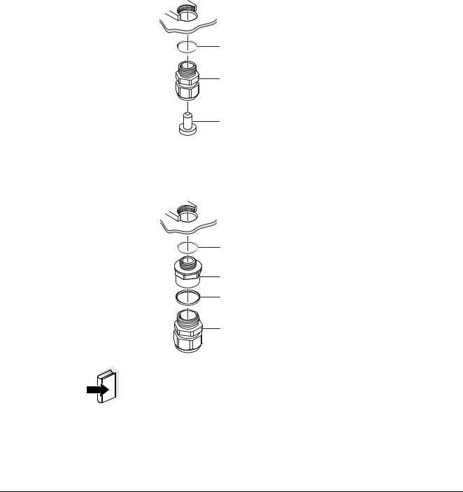
Cable glands All electric cables are fed from below via prepared openings in the enclosure of the module. Cable glands with different clamping ranges are included with the module to provide sealing between the cable and enclosure as well as for strain relief. Select the matching cable gland for the respective cable diameter:
Small, clamping range 4.5 to 10 mm. This cable gland is suitable for all IQ SENSOR NET sensor cables.
sealing ring 20 x 15 x 1 mm
cable gland M16
blind plug
Large, clamping range 7 to 13 mm. This cable gland is required for cable sheaths with an outside diameter of more than 10 mm and is screwed into the enclosure via an extension piece.
sealing ring 20 x 15 x 1 mm
extension piece M16/M20
sealing ring 24 x 19 x 2 mm
cable gland M20
Note
If necessary, you can order more large cable glands in a set of 4 pieces (Model EW/1, Order No. 480 051).
3 - 2 |
ba76032e01 |
01/2012 |
MIQ/CR3; DIQ/CR3 |
Installation |
|
|
General installation |
Observe the following points when attaching connecting wires to the |
instructions |
terminal strip |
|
Shorten all wires to be used to the length required for the installation |
|
Always fit all the ends of the wires with wire end sleeves before |
|
connecting them to the terminal strip |
|
Any wires that are not used and project into the enclosure must be |
|
cut off as closely as possible to the cable gland. |
|
Screw a small cable gland with sealing ring into each remaining free |
|
opening and close it with a blind plug. |
Warning
No free wires must be allowed to project into the enclosure. Otherwise, there is a danger that areas safe to contact could come into contact with dangerous voltages which could result in life threatening electric shock when working with the IQ SENSOR NET. Always cut off any wires that are not in use as closely as possible to the cable gland.
ba76032e01 |
01/2012 |
3 - 3 |

Installation |
MIQ/CR3; DIQ/CR3 |
|
|
3.4Connections to the relay and current outputs
Warning
If external electrical circuits that are subject to the danger of physical contact are incorrectly connected to the relay contacts, there may be a danger of life threatening electric shock. Electrical circuits are regarded to be subject to the danger of physical contact when there are voltages higher than the Safety Extra Low Voltage (SELV).
Pay attention to the following points during installation:
Electrical circuits subject to the danger of physical contact must only be connected by a qualified electrician.
Electrical circuits subject to the danger of physical contact must only be connected when they are voltage-free.
If electrical circuits subject to the danger of physical contact are switched with a relay, no circuit that is not subject to this danger (e. g. the MIQ/CHV module) may be operated in the same output module. Use an additional output module for such applications.
Switching voltages and switching currents on the relay contacts must not exceed the values specified in chapter 6 TECHNICAL DATA. Protect electrical circuits against currents that are too high with an electrical fuse.
Only single-phase consumers can be switched with the relays. Under no circumstances must multiphase consumers be switched with the aid of several relays (example three-phase current driven pumps). Always switch multiphase consumers via a protective relay.
After the output module has been installed, it may only be opened if all external voltages have been switched off beforehand.
Materials required Wire end sleeves, suitable for the connecting wires, with suitable crimping tool
4 x screwed cable gland with sealing ring (scope of delivery of the combi output module).
Tools Cable stripping knife
Wire stripper
Phillips screw driver
Small screw driver
3 - 4 |
ba76032e01 |
01/2012 |

MIQ/CR3; DIQ/CR3 |
Installation |
|
|
Connecting lines to the
1 Open the module.
terminal strip
 2
2
1 |
X18 |
|
X17 |
X16 |
|
X15 |
X14 |
|
X13 |
X12 |
|
X11 |
X10 |
|
X9 |
X8 |
|
X7 |
|||||||||||||||
3 |
250 VAC |
250 VAC |
250 VAC |
0/4...20mA |
0/4...20mA |
0/4...20mA |
|||||||||||||||||||||||||||
5 A AC |
5 A AC |
5 A AC |
|
|
|
|
|
|
|
|
|
|
|
|
|
|
|
|
|
|
|
|
|
||||||||||
|
|
|
|
|
|
|
|
|
|
|
|
|
|
|
|
|
|
|
|
|
|
|
|
|
|
|
|
|
|
|
|||
|
|
|
|
|
|
|
|
|
|
|
|
|
|
|
|
|
|
|
|
|
|
|
|
|
|
|
|
|
|
|
|
|
|
|
|
|
|
|
|
|
|
|
|
|
|
|
+ REC - |
+ REC - |
+ REC - |
||||||||||||||||||
|
R1 |
R2 |
R3 |
|
|
C1 |
|
|
|
|
|
C2 |
|
|
|
|
|
C3 |
|
|
|
||||||||||||
|
|
|
|
|
Relay |
|
|
|
|
|
Current output |
|
|
|
|||||||||||||||||||
X6 |
X5 |
X4 |
RED |
SHIELD |
GREEN |
|
|
|
SENSORNET 2
ON
OFF
 TERMINA SN TOR
X3 |
X2 |
X1 |
RED |
SHIELD |
GREEN |
|
|
|
SENSORNET 1
Fig. 3-1 Terminal strip with the relay and current connections
2Screw the cable gland (pos. 1 in Fig. 3-1) with the sealing ring (pos. 2) into the module housing.
3Loosen the coupling ring (pos. 3 in Fig. 3-1).
4Feed the line through the cable gland in the module housing.
5Connect the wires to the terminal strip. While doing so, pay attention to the specifications on the label located under the terminal strip.
6Tighten the coupling ring (pos. 3 in Fig. 3-1).
Warning
No free wires must be allowed to project into the enclosure. Otherwise, there is a danger that safe areas could come into contact with dangerous voltages. This could result in life threatening electric shock when working with the IQ SENSOR NET. Always cut off any wires that are not in use as closely as possible to the cable gland.
ba76032e01 |
01/2012 |
3 - 5 |

Installation |
MIQ/CR3; DIQ/CR3 |
|
|
7 Close the module.
3 - 6 |
ba76032e01 |
01/2012 |

MIQ/CR3; DIQ/CR3 |
Settings |
|
|
4 Settings
The combi output module has three relays outputs and three current outputs.
Relay outputs operate as openers or closers.
Current outputs provide a current that depends on the measured value.
On the terminal or Universal Transmitter, you can
assign names to the outputs (with the 2020 XT system only, see section 4.2).
link outputs with sensors (see section 4.3)
delete links of outputs with sensors (see section 4.4)
adjust outputs (see section 4.5 and section 4.6)
check the condition of the outputs (see section 4.7)
Basic information on how to use relay outputs is given in section 4.1.
|
|
|
Note |
|
|
|
|
|
|
|
|
|
|
|
The general operating principles are given in the relevant system |
|
|
|
operating manual or in the component operating manual of the terminal |
|
|
|
components. |
Functions of current and |
Relay output (see section 4.5) |
||
relay outputs |
System monitoring |
||
|
|
|
|
|
|
|
Sensor monitoring |
|
|
|
Limit indicator |
|
|
|
Frequency controller |
|
|
|
Pulse-width contr. |
|
|
|
Cleaning |
|
|
|
Sensor-controlled |
|
|
|
Manual control |
|
|
|
Alarm contact (with the 2020 XT system only) |
|
|
|
Current output (see section 4.6) |
|
|
|
Recorder |
|
|
|
PID controller |
|
|
|
Fixed current value |
ba76032e01 |
01/2012 |
4 - 1 |

Settings |
MIQ/CR3; DIQ/CR3 |
|
|
4.1Basic information on relay functions
In this chapter, you will find general basic information concerning the following relay functions:
Monitoring (see section 4.1.1)
Limit indicator (see section 4.1.2)
Proportional output (see section 4.1.3)
4.1.1Monitoring
When using a relay for monitoring, a relay action (Open, Close) occurs when certain states occur. This function is suitable, e.g. for the monitoring of errors in the system.
Note
For monitoring functions, use the relay preferably as an opener (see section 4.5.1). In the case of an error, the relay opens. As a result, the monitoring function operates even if, e.g. the supply voltage fails.
4 - 2 |
ba76032e01 |
01/2012 |

MIQ/CR3; DIQ/CR3 |
Settings |
|
|
4.1.2Limit indicator
With a limit indicator, a relay switches when a specified limiting value is exceeded or undercut.
Limit indicators can be used in the following way:
Monitoring a limiting value using a relay:
when a limiting value (upper or lower limiting value) is exceeded or undercut, a relay switches. The Open or Close relay actions are possible in each case (see page 4-4).
Monitoring two limiting values using two relays:
If the upper limiting value is exceeded or undercut, a relay switches, and if the lower limiting value is exceeded or undercut, another relay switches. The Open or Close relay actions are possible in each case (see page 4-4).
Note
If the simple monitoring function (Open, Close) with one or two relays is not sufficient, use proportional output (see section 4.1.3).
ba76032e01 |
01/2012 |
4 - 3 |
Settings |
MIQ/CR3; DIQ/CR3 |
|
|
Monitoring limiting values using one or two relays
Measured |
t1 |
|
|
|
|
value |
|
|
|
|
|
|
|
|
|
|
|
UL |
Relay 1 |
|
|
t1 |
|
|
|
|
|
Hysteresis UL |
|
|
|
|
2 |
|
|
|
|
|
|
6 |
|
|
|
1 |
3 |
4 |
|
|
|
|
|||
|
|
|
|
|
|
|
|
|
|
|
5 |
LL |
|
|
|
|
Hysteresis LL |
Relay 2 |
|
|
|
|
|
|
|
|
|
|
|
t2 t2
Time
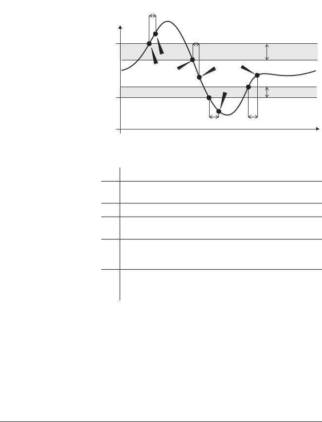
Fig. 4-1 Switching points for relays with the function of a limit indicator
1Upper limit value (relay 1) exceeded
2Selected switching delay t1 for relay 1 expired Relay 1 switches
3Hysteresis for upper limiting value (relay 1) undercut
4Selected switching delay t1 for relay 1 expired Relay 1 switches back
5Lower limit value (relay 2) undercut
Selected switching delay t2 for relay 2 expired Relay 2 switches
6Hysteresis for lower limiting value (relay 2) exceeded Selected switching delay t2 for relay 2 expired Relay 2 switches back
A switching delay (t) can be set up for each relay for switching processes. This is the time period for which a limiting value must be exceeded before the relay switches. This prevents frequent switching if the measured values are close to the limiting value.
4 - 4 |
ba76032e01 |
01/2012 |

MIQ/CR3; DIQ/CR3 |
Settings |
|
|
4.1.3Proportional output
In the case of proportional output, a relay switches cyclically on and off in a defined measured value range (proportional range). At the same time, the relay switches with a:
duration of operation that corresponds to the measured value (pulse-width output, see page 4-7) or
switching frequency (frequency output, see page 4-8).
Proportional outputs can be used in the following way:
Output with one relay:
An output range is defined with a Start value and an End value. No output takes place above and below the output range
(see page 4-6).
Output with two relays:
An output range is defined for each relay with a Start value and an End value. One relay outputs in the upper output range and a further relay in the lower output range (see page 4-6).
ba76032e01 |
01/2012 |
4 - 5 |
Settings |
MIQ/CR3; DIQ/CR3 |
|
|
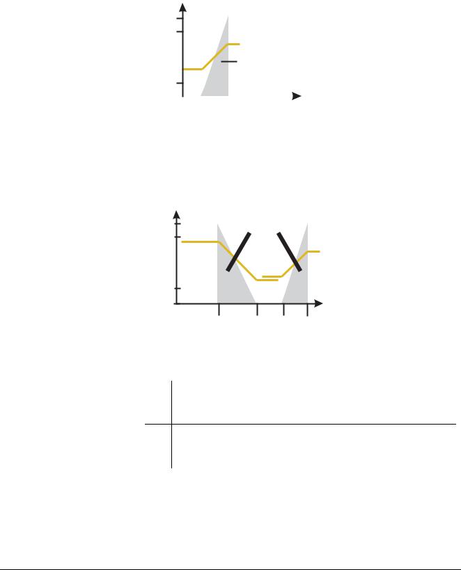
Output with one relay
Output with two relays
Switching frequency f or
Pulse width v
100
90
Proportional band
10
0 |
|
|
|
|
Measured value |
|
|
|
|
||
|
|
|
|
|
|
1 2
Fig. 4-2 Output with one relay
Switching frequency f or |
|
|
|
Pulse width v |
Proportional bands |
||
|
|||
100 |
Relay 1 and 2 |
|
|
90 |
|
|
|
10 |
|
|
|
0 |
|
|
Measured value |
2 |
1 |
1 |
2 |
Relay 1 |
Relay 2 |
||
Fig. 4-3 Output with two relays |
|
|
|
1Start value
Measured value with a minimum pulse width or switching frequency
2End value
Measured value with a maximum pulse width or switching frequency
4 - 6 |
ba76032e01 |
01/2012 |
Loading...