


6-SERIES DRINKING WATER SYSTEMS
600DW-B Sonde
6920DW Sonde
650 MDS Display/Logger
6500 Process Monitor
Environmental
Monitoring
Systems

SAFETY NOTES
TECHNICAL SUPPORT AND WARRANTY INFORMATION
Contact information for technical support and warranty information on YSI’s Environmental Monitoring Systems products can be found in Section 8, Warranty and Service Information.
COMPLIANCE
When using the YSI 6-Series sondes in a European Community (CE) country, please be aware that electromagnetic compatibility (EMC) performance issues may occur under certain conditions, such as when the sonde is exposed to certain radio frequency fields.
If you are concerned with these issues, consult the Declaration of Conformity that was enclosed with your instrument. Specific conditions where temporary sensor problems may occur are listed in this document.
If you are unable to locate the Declaration of Conformity that was shipped with your instrument, contact your local YSI representative, or YSI Customer Service in Yellow Springs, Ohio for a copy of the document. See Section 8, Warranty and Service Information for contact information.
SPECIFICATIONS
For general specifications for all YSI Environmental Monitoring Systems products included in this manual, please see Appendix M, Specifications.
GENERAL SAFETY CONSIDERATIONS
For Health and Safety issues concerning the use of the calibration solutions with the sondes, please see Appendix A, Health and Safety.
NOTICE
Information contained in this manual is subject to change without notice. Effort has been made to make the information contained in this manual complete, accurate, and current. YSI shall not be held responsible for errors or omissions in this operations manual.
WARNING:
When caring for your sonde, remember that the sonde is sealed at the factory, and there is never a need to gain access to the interior circuitry of the sonde. In fact, if you attempt to disassemble the sonde, you would void the manufacturer's warranty.
TABLE OF CONTENTS
SECTION 1 INTRODUCTION |
|
|
1.1 ABOUT YSI |
1-1 |
|
1.2 HOW TO USE THIS MANUAL |
1-1 |
|
1.3 UNPACKING AND INSPECTION |
1-2 |
|
SECTION 2 6920DW AND 600DW-B SONDES |
|
|
2.1 |
GETTING STARTED |
2-1 |
2.2 |
CONNECTING YOUR SONDE |
2-2 |
2.3 |
PREPARING THE SONDE FOR USE |
2-5 |
2.4 |
ECOWATCH FOR WINDOWS – GETTING STARTED |
2-18 |
2.5 |
SONDE SOFTWARE SETUP |
2-18 |
2.6 |
GETTING READY TO CALIBRATE |
2-26 |
2.7 |
TAKING READINGS |
2-39 |
2.8 |
USING ECOWATCH TO UPLOAD AND ANALYZE DATA |
2-45 |
2.9 |
SONDE MENU |
2-59 |
2.10 CARE, MAINTENANCE, AND STORAGE |
2-95 |
|
SECTION 3 650 MDS DATA LOGGER |
|
|
3.1 INTRODUCTION |
3-1 |
|
3.2 GETTING STARTED |
3-1 |
|
3.3 SETTING UP THE 650 |
3-18 |
|
3.4 SONDE MENU INTERFACE |
3-21 |
|
3.5 LOGGING DATA WITH THE 650 |
3-27 |
|
3.6 MANAGING 650 FILES |
3-46 |
|
3.7 UPLOADING DATA FROM SONDES |
3-51 |
|
3.8 USING GPS WITH 650 |
3-51 |
|
3.9 USING THE 650 BAROMETER |
3-53 |
|
3.10 UPGRADING 650 SOFTWARE |
3-55 |
|
3.11 TROUBLESHOOTING |
3-56 |
|
3.12 FERRITE BEAD INSTALLATION |
3-57 |
|
3.13 SAFETY CONSIDERATIONS |
3-58 |
|
3.14 650 MDS SPECIFICATIONS |
3-61 |
|
SECTION 4 ECOWATCH FOR WINDOWS |
|
|
4.1 |
INTRODUCTION |
4-1 |
4.2 |
DATA ACQUISITION AND ANALYSIS |
4-7 |
4.3 ECOWATCH MENU |
4-12 |
|
SECTION 5 PRINCIPLES OF OPERATION |
|
|
5.1 |
CONDUCTIVITY |
5-1 |
5.2 |
SALINITY |
5-2 |
5.3 |
TOTAL DISSOLVED SOLIDS (TDS) |
5-2 |
5.4 |
OXIDATION REDUCTION POTENTIAL (ORP) |
5-3 |
5.5 pH |
5-4 |
|
5.6 TEMPERATURE |
5-5 |
|
5.7 FREE CHLORINE |
5-5 |
|
5.8 NITRATE |
5-9 |
|
5.9 AMMONIUM AND AMMONIA |
5-10 |
|
5.10 CHLORIDE |
5-12 |
|
5.11 TURBIDITY |
5-14 |
|
5.12 CHLOROPHYLL |
5-16 |
|
5.13 RHODAMINE WT |
5-23 |
|
SECTION 6 TROUBLE SHOOTING |
|
||
6.1 |
CALIBRATION ERRORS |
6-1 |
|
6.2 |
SONDE COMMUNICATION PROBLEMS |
6-2 |
|
6.3 |
SENSOR PERFORMANCE PROBLEMS |
6-3 |
|
SECTION 7 COMMUNICATION |
|
||
7.1 |
OVERVIEW |
7-1 |
|
7.2 |
HARDWARE INTERFACE |
7-1 |
|
7.3 RS-232 INTERFACE |
7-2 |
||
7.4 SDI-12 INTERFACE |
7.2 |
||
SECTION 8 WARRANTY AND SERVICE INFORMATION |
|
||
8.1 |
LIMITATIONS OF WARRANTY |
8-1 |
|
8.2 |
AUTHORIZED SERVICE CENTERS |
8-2 |
|
8.3 CLEANING INSTRUCTIONS |
8-2 |
||
APPENDIX A HEALTH AND SAFETY |
A-1 |
||
APPENDIX B |
REQUIRED NOTICE |
B-1 |
|
APPENDIX C ACCESSORIES AND CALIBRATION STANDARDS |
C-1 |
||
APPENDIX D |
EMC PERFORMANCE |
D-1 |
|
APPENDIX E |
SPECIFICATIONS |
E-1 |
|
APPENDIX F QUICK START GUIDE TO DRINKING WATER APPLICATIONS |
F-1 |
||
APPENDIX G USING YOUR DW SONDE WITH A YSI 6500 PROCESS MONITOR |
G-1 |
||
APPENDIX H FREQUENTLY ASKED QUESTION ABOUT DW SYSTEMS |
H-1 |
||

Introduction |
Section 1 |
SECTION 1 INTRODUCTION
1.1 ABOUT YSI INCORPORATED
From a three-man partnership in the basement of the Antioch College science building in 1948, YSI has grown into a commercial enterprise designing and manufacturing precision measurement sensors and control instruments for users around the world. Although our range of products is broad, we focus on four major markets: water testing and monitoring, health care, bioprocessing, and OEM temperature measurement.
In the 1950s, Hardy Trolander and David Case made the first practical electronic thermometer using a thermistor. This equipment was developed to supply Dr. Leland Clark with a highly sensitive and precise temperature sensor for the original heart-lung machine. The collaboration with Dr. Clark has been critical to the success of the company. In the 1960s, YSI refined a Clark invention, the membrane covered polarographic electrode, and commercialized oxygen sensors and meters which revolutionized the way dissolved oxygen was measured in wastewater treatment plants and environmental water. Today, geologists, biologists, environmental enforcement personnel, officials of water utilities and fish farmers recognize us as the leader in dissolved oxygen measurement.
In the 1970s, YSI again worked with Clark to commercialize one of his many inventions, the enzyme membrane. This development resulted in the first practical use of a biosensor, in the form of a membrane based on immobilized glucose oxidase, to measure blood sugar accurately and rapidly. In the next few years, this technology was extended to other enzymes, including lactate oxidase for applications in biotechnology, health care, and sports medicine.
In the early 1990s, YSI launched a line of multi-parameter water monitoring systems to address the emerging need to measure non-point source pollution. Today we have thousands of instruments in the field that operate with the push of a button, store data in memory, and communicate with computers. These instruments (described in this manual) are ideal for profiling and monitoring water conditions in industrial and wastewater effluents, lakes, rivers, wetlands, estuaries, coastal waters, and monitoring wells. If the instrument has ‘on board’ battery power, it can be left unattended for weeks at a time with measurement parameters sampled at your setup interval and data securely saved in the unit's internal memory. The fast response of YSI’s sensors make the systems ideal for vertical profiling, and the small size of some our sondes allows them to fit down 2-inch diameter monitoring wells. All of YSI’s multi-parameter systems for surface and groundwater feature the YSI-patented Rapid Pulse Dissolved Oxygen Sensor, which exhibits low-stirring dependence and provides accurate results without an expensive, bulky, and power-intensive stirrer.
YSI has established a worldwide network of selling partners in 54 countries that includes laboratory supply dealers, manufacturers' representatives, and YSI’s sales force. A subsidiary, YSI UK, distributes products in the United Kingdom, a sales office in Hong Kong supports YSI’s distribution partners in Asia Pacific, and YSI Japan supports distribution partners in Japan.
Through an employee stock ownership plan (ESOP), every employee is one of the owners. In 1994, the ESOP Association named YSI the ESOP Company of the Year. YSI is proud of its products and are committed to meeting or exceeding customers' expectations.
1.2 HOW TO USE THIS MANUAL
The manual is organized to let you quickly understand and operate the YSI 6-Series drinking water (DW) systems. However, it cannot be stressed too strongly that informed and safe operation is more than just
YSI Incorporated Drinking Water Monitoring Systems Operations Manual |
1-1 |

Introduction |
Section 1 |
knowing which buttons to push. An understanding of the principles of operation, calibration techniques, and system setup is necessary to obtain accurate and meaningful results.
Because of the many features, configurations and applications of these versatile products, some sections of this manual may not apply to the specific system you have purchased.
If you have any questions about this product or its application, please contact YSI’s customer service department or authorized dealer for assistance. See Section 8, Warranty and Service Information for contact information.
1.3 UNPACKING AND INSPECTION
Inspect the outside of the shipping box for damage. If any damage is detected, contact your shipping carrier immediately. Remove the equipment from the shipping box. Some parts or supplies are loose in the shipping box so check the packing material carefully. Check off all of the items on the packing list and inspect all of the assemblies and components for damage.
If any parts are damaged or missing, contact your YSI representative immediately. If you purchased the equipment directly from YSI, or if you do not know from which YSI representative your equipment was purchased, refer to Section 8, Warranty and Service Information for contact information.
YSI Incorporated Drinking Water Monitoring Systems Operations Manual |
1-2 |

Sondes |
Section 2 |
SECTION 2 6920DW AND 600DW-B SONDES
2.1 GETTING STARTED
The 6920DW and 600DW-B-B Drinking Water Monitoring Systems are multi-parameter, water quality measurement, and data collection systems. Their primary application is the monitoring of drinking water using a flow cell and a free chlorine sensor is provided with each instrument since this parameter is very important in assessing the quality of drinking water. However, these instruments can also be used in a variety of research, assessment, and regulatory compliance applications without a flow cell as long as the user realizes that the performance of the free chlorine sensor will be significantly compromised under these conditions. The primary difference between the “DW” instruments and those provided by YSI for surface and ground water applications is that the oxygen sensor for the standard sondes has been replaced by a free chlorine sensor in the 6920DW and 600DW-B. The free chlorine sensor also requires a different circuit board which is resident in the instrument and this means that “DW” sondes are not capable of dissolved oxygen measurement and, vice versa, standard sondes are not capable of free chlorine measurement even though the probes themselves will fit in either of the instruments. Section 2 concentrates on how to set up operate the “DW” sondes. For the purpose of terminology in this manual it should be realized that a sonde is a torpedo-shaped water quality monitoring device that is placed in the water to gather water quality data. Sondes may have multiple probes. Each probe may have one or more sensors that read water quality data.
The following list contains parameters that your sonde may measure. See Appendix E Specifications for the specific parameters of each sonde.
•Free Chlorine
•Conductivity
•Specific Conductance
•Salinity
•Total Dissolved Solids
•Resistivity
•Temperature
•pH
•ORP
•Turbidity
•Nitrate-N
•Ammonia-N
•Ammonium-N
•Chloride
•Chlorophyll
•Rhodamine WT
This section is designed to quickly familiarize you with the hardware and software components of the “DW” sondes and their accessories. You will then proceed to probe installations, cable connections, software installation and finally basic communication with your Sonde. Diagrams, menu flow charts and basic written instructions will guide you through basic hardware and software setup.
YSI Incorporated Drinking Water Monitoring Systems Operations Manual |
2-1 |
Sondes |
Section 2 |
2.2 CONNECTING YOUR SONDE
There are a number of ways in which you may connect the sondes to various computers, data collection devices and VT-100 terminal emulators. To utilize the configuration that will work best for your application, make sure that you have all of the components that are necessary. The following list and diagrams provide a few possible configurations.
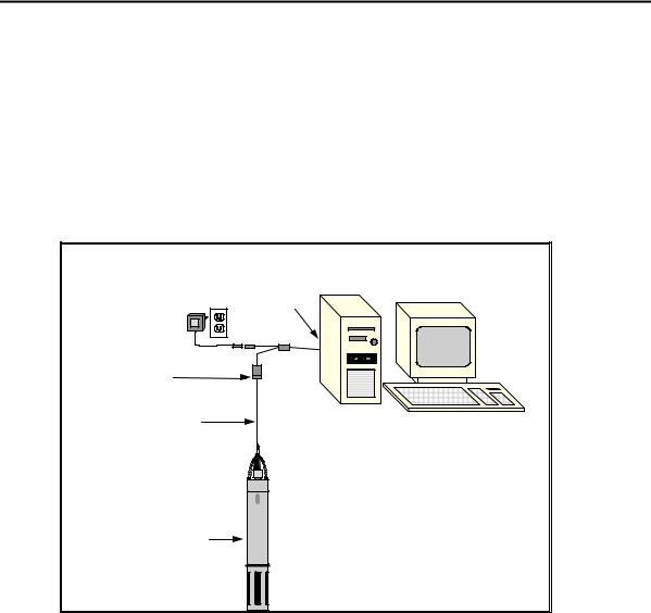
Sonde to Lab Computer (recommended for initial setup)
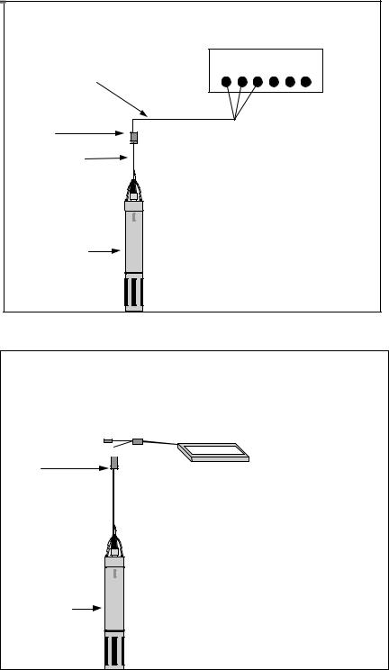
Sonde to Data Collection Platform
Sonde to Portable Computer
Sonde to YSI 650 MDS Display/Logger
Sonde to Lab Computer
|
DB-9 |
|
Power Supply* |
6095B |
|
6651: 220 VAC |
||
|
||
6038: 110 VAC |
Adapter |
|
MS-8 |
|
|
Field Cable |
|
You will need...
Sonde
*Not required if you use sonde battery power.
+
-
YSI 6920
θSonde
θField Cable
θComputer with Com Port
θ6095B MS-8/DB-9 Adapter
θPower Supply *
YSI Incorporated Drinking Water Monitoring Systems Operations Manual |
2-2 |
Sondes |
Section 2 |
Sonde to Data Collection Platform
DCP
6096 MS-8 Adapter with Flying Leads
MS-8 |
|
Field Cable |
You will need... |
|
Sonde
+
-
YSI 692 0
TSonde
TField Cable
T6096 Adapter with leads
TData Collection Platform
Sonde to Portable Computer
DB-9 6095B

 Adapter
MS-8
Field Cable 
You will need...
T Sonde
Sonde
+
-
YSI 692 0
TField Cable
TComputer with Com Port
T6095B MS-8/DB-9 Adapter
YSI Incorporated Drinking Water Monitoring Systems Operations Manual |
2-3 |
Sondes |
Section 2 |
Sonde to 650 Display/Logger
MS-8 
Field Cable 
+
-
YS
I
Sonde 69
20
650 MDS
You will need...
TSonde
TField Cable
T650 MDS Display/Logger
YSI 650 operates on C-cells or rechargeable batteries.
Sonde to 650 Display/Logger Sonde to 6500 Process Monitor
You will need...
Sonde
-
Field Cable
650 MDS Display/Logger
YSI 6500 operates on 90-230 V AC Power.
YSI Incorporated Drinking Water Monitoring Systems Operations Manual |
2-4 |
Sondes |
Section 2 |
2.3 PREPARING THE SONDE FOR USE
To prepare the sonde for calibration and operation, you need to install probes (sensors) into the connectors on the sonde bulkhead. In addition to probe installation, you need to install a new membrane on the YSI 6572 Free Chlorine Probe. It is highly recommended that you install the free chlorine membrane before installing the probe onto the bulkhead. The next step is providing power for the sondes, through batteries or AC, and then connecting a cable. The four steps necessary for getting your sonde ready for use are listed below.
Step 1 Installing the Free Chlorine Membrane – Section 2.3.1
Step 2 Installing the Probes – Section 2.3.2
Step 3 Supplying Power – Section 2.3.3
Step 4 Connecting a Cable – Section 2.3.4
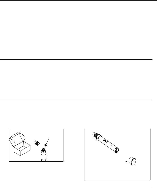
2.3.1 STEP 1 - INSTALLING THE FREE CHLORINE PROBE MEMBRANE
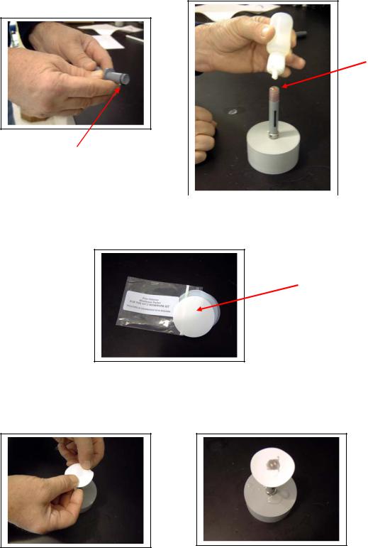
The 6572 Free Chlorine probe is shipped with a protective cap on the sensor tip which must be removed before proceeding . Handle the probe with care. It is very important not to drop the probe and/or gouge the probe tip. See Section 2.10.2, Probe Care and Maintenance, for information on how often the membrane should be replaced.
Unpack the YSI 6572 Free Chlorine Probe Kit and follow the instructions below.
FREE CHLORINE SENSOR ELECTROLYTE PREPARATION
Open the 6573 membrane kit which was shipped with your instrument and prepare the electrolyte solution. Dissolve the KCl in the dropper bottle by filling it to the neck with deionized or distilled water and shaking until the solids are fully dissolved. After the KCl is dissolved, wait a few minutes until the solution is free of bubbles.
1. |
ADD DI OR DISTILLED |
2. |
|
WATER |
|
PROTECTIVECAP
FREE CHLORINE SENSOR MEMBRANE INSTALLATION
Remove the protective Teflon membrane and O-ring from the sensor end of the YSI 6572 Free Chlorine probe. CAUTION: The Teflon membrane MUST be removed for proper sensor function.
Remove the protective cap is installed on the connector end of the probe.
YSI Incorporated Drinking Water Monitoring Systems Operations Manual |
2-5 |
Sondes |
Section 2 |
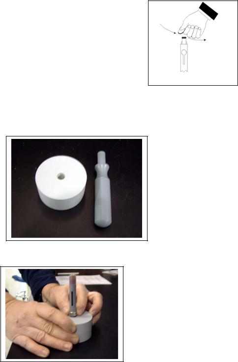
Locate the 6035 Reconditioning Kit which was supplied with your 6572 Free Chlorine Probe. Use one of circular sanding disks the 6035 Reconditioning Kit to sand the face of the 6572 Probe according to the following instructions.
•Hold the probe in a vertical position, place a sanding disk under your thumb, and stroke the probe face in a direction parallel to the platinum electrode (located between
the two silver electrodes). The motion is similar to that used in striking a match. Usually 10-15 strokes of the sanding disk are sufficient to remove black deposits on the silver electrodes.
However, in extreme cases, more sanding may be required to regenerate the original silver surface.
•Rinse the probe tip well with purified water to remove dust from sanding.
CAUTION: You must sand your free chlorine sensor as described above prior to installing a membrane to insure the surface tension for probe surface/membrane interface.
Locate the YSI 6574 O-ring Installation Kit which was shipped with your sonde. Note that the kit contains two items – a circular plate with a threaded hole and a cylindrical tool with a screwdriver-style handle as shown in the picture below.
Thread the nut on the end of the 6572 probe into the base plate as shown in the picture below.
Place an o-ring from the 6573 membrane kit in the groove at the bottom of the tool as shown in the picture below left.
YSI Incorporated Drinking Water Monitoring Systems Operations Manual |
2-6 |
Sondes |
Section 2 |
Apply a few drops of KCl solution to the tip of the probe as shown in the picture above right. The fluid should completely fill the small moat around the electrodes and form a meniscus on the tip of the sensor.
Meniscus
O-Ring in Groove |
|
|
|
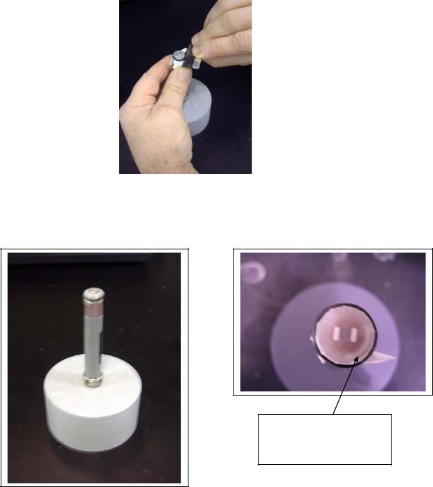
Remove a white membrane sheet from the package in the |
picture |
||
below. |
|
|
|
|
|
|
|
CAUTION: The blue sheets are simply protective spacers and CANNOT be used as membranes for the free chlorine sensor.
White Membrane
As shown in the pictures below, lay the membrane on the probe tip that contains the electrolyte so that the probe tip is approximately in the middle of the membrane.
YSI Incorporated Drinking Water Monitoring Systems Operations Manual |
2-7 |

Sondes |
Section 2 |
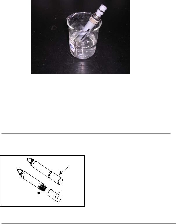
As shown in the picture below, place the bottom of the o-ring installation tool over membrane/probe face and press down securely.
As shown in the picture below left, roll the o-ring off of the end of the installation tool so that it resides in the o-ring groove of the probe. Be sure to hold onto the O-ring prior to removing the installation tool so that it does not pop out of the groove. Then, as shown below right, remove the installation tool and make certain that the o-ring is centered in the groove on probe end.
As shown in the picture below, use a razor blade or knife to trim away the excess membrane material.
YSI Incorporated Drinking Water Monitoring Systems Operations Manual |
2-8 |
Sondes |
|
Section 2 |
|
|
|
|
|
|
The pictures below show a properly installed free chlorine membrane. Note that, because the membrane will not stretch, there may be some points where the membrane is slightly “bunched up” in the o-ring groove. This effect is normal and will not affect sensor function. Also note that the presence of bubbles under the membrane is also normal and should not affect probe function
Note the presence of a bubble after installation. This is acceptable for a free chlorine membrane.
`
After installing the membrane, either proceed immediately to the sensor activation protocol described above in the Quick Start Guide or store the probe in a beaker of tap water (NOT deioinized or distilled water) as shown in the picture below to prevent drying out. Be sure to place the probe GENTLY into the beaker to avoid damaging the membrane integrity.
YSI Incorporated Drinking Water Monitoring Systems Operations Manual |
2-9 |
Sondes |
|
Section 2 |
|
|
|
|
|
|
NOTE CAREFULLY: Users who are accustomed to installing a Teflon membrane on a YSI dissolved oxygen sensor should note that the methods recommended for the Teflon installation are not likely to work well for the free chlorine membrane because this membrane cannot be stretched. Therefore, dissolved oxygen membrane installation techniques which are outline in the manuals for various YSI instruments, including standard 6-series sondes utilizing the 6562 Rapid Pulse DO sensor, are NOT RECOMMENDED for the free chlorine membrane installation.
2.3.2 STEP 2 - INSTALLING THE PROBES
Remove the calibration cup from your sonde by hand as shown below to expose the bulkhead.
TRANSPORT CUP
BULKHEAD WITH 
PROBE PORT PLUGS
REMOVING THE PORT PLUGS
Using the long extended end of the probe installation tool supplied in the YSI 6570 Maintenance Kit, remove the port plugs. Save all the port plugs
for possible future use.
YSI Incorporated Drinking Water Monitoring Systems Operations Manual |
2-10 |

Sondes |
Section 2 |
There are a variety of probe options for the sondes. The figures below and to the right illustrate the uses of the common tool for port plug removal. Note that this tool will also be used to install the various probes.
If the tool is misplaced or lost, you may use 7/64” and 9/64” hex keys as substitutes.
OPTIC |
PORT PLUG |
INSTALLATION |
TOOL |
NOTE: You may need pliers to remove the ISE port plugs, but do not use pliers to tighten the ISE probes. Hand-tighten only.
Now refer to the figures below to find the probe locations in your sonde.
DO, COND., & |
pH/ORPPORT |
PLUGS |
INSTALLATION |
TOOL |
ISE PORT PLUG |
PLIERS |
(SLIP JAWS) |
600DW-B SONDE BULKHEAD
6572 Free Chlorine = 3-pin connector
6560 Conductivity/Temperature = 6-pin connector
6561 pH = 4-pin connector
6565 Combo pH/ORP = 4-pin connector
6566 Fouling Resistant pH//ORP = 4 pin connector
6561FG pH (Flat Glass) = 4-pin connector
6565FG pH/ORP (Flat Glass) = 4-pin connector
FREE |
CONDUCTIVITY/ |
|
CHLORINE |
||
TEMPERATURE |
||
6572 |
||
6560 |
||
|
ALL ISE
PROBES
YSI Incorporated Drinking Water Monitoring Systems Operations Manual |
2-11 |

Sondes |
Section 2 |
6920DW SONDE BULKHEAD
6572 Free chlorine probe = 3-pin connector
6560 Conductivity/Temperature = 6-pin connector
6561 pH = 4-pin connector
6565 Combo pH/ORP = 4-pin connector
6566 Fouling Resistant pH//ORP = 4 pin connector
6561FG pH (Flat Glass) = 4-pin connector
6565FG pH/ORP (Flat Glass) = 4-pin connector
6882 Chloride Probe = leaf spring connector
6883 Ammonium Probe = leaf spring connector
6884 Nitrate Probe = leaf spring connector
6026 Turbidity Probe, Wiping = 8 pin connector
6136 Turbidity Probe, Wiping = 8 pin connector
6025 Chlorophyll Probe, Wiping = 8 pin connector
6130 Rhodamine WT Probe, Wiping = 8 pin connector
LUBRICATE O-RINGS
|
COND/TEMP |
|
ISE1/ISE2 |
|
FREE |
pH/ORP |
|
CHLORINE |
TURBIDITY |
|
MOUNTING SCREW |
CHLOROPHYLL |
|
|
|
1 OF 2 |
|
RHODAMINE WT |
|
|
|
|
|
|
3 |
|
|
5 |
|
ISE3 |
4 |
ISE5 |
ISE4
Apply a thin coat of O-ring lubricant, supplied in the YSI 6570 Maintenance Kit, to the O-rings on the connector side of each probe that is to be installed.
CAUTION: Make sure that there are NO contaminants
between the O-ring and the probe. Contaminants that are present under the O-ring may cause the O-ring to leak
when the sonde is deployed.
LUBRICATE O-RINGS |
NOTE: Before installing any probe into the sonde bulkhead, be sure that the probe port is free of moisture. If there is moisture present, you may use compressed air to blow out the remaining moisture.
INSTALLING THE TURBIDITY, CHLOROPHYLL, AND RHODAMINE WT PROBES
If you have a turbidity, chlorophyll, and/or rhodamine WT probe, it is recommended that the optical sensors be installed first. If you are not installing one of these probes, do not remove the port plug, and go on to the next probe installation.
YSI Incorporated Drinking Water Monitoring Systems Operations Manual |
2-12 |

Sondes |
Section 2 |
All optic probes, 6026 and 6136 turbidity, 6025 chlorophyll, and 6130 rhodamine WT are installed in the same way. Install the probe into the center port, seating the pins of the two connectors before you begin to tighten. Tighten the probe nut to the bulkhead using the short extended end of the tool supplied with the probe. Do not over-tighten.
CAUTION: Be careful not to cross-thread the probe nut.
Note that the YSI 6920DW sondes can accept only a single turbidity, chlorophyll, or rhodamine WT probe.
INSTALLATION
TOOL
OPTIC PROBE
INSTALLING THE FREE CHLORINE PROBE, CONDUCTIVITY/TEMP AND pH/ORP PROBES
Insert the probe into the correct port and gently rotate the probe until the two connectors align.
The probes have slip nuts that require a small probe |
CL2 PROBE |
|
|
installation tool to tighten the probe. With the connectors |
|
aligned, screw down the probe nut using the long extended |
|
end of the probe installation tool. Do not over-tighten. |
|
CAUTION: Do not cross thread the probe nut. |
PROBE INSTALLATION |
TOOL |
INSTALLING THE ISE PROBES
The Ammonium, Nitrate and Chloride ISE probes do not have slip nuts and should be installed without tools. Use only your fingers to tighten. Any ISE probe can be installed in any of the three ports labeled “3”, “4”, and “5” on the sonde bulkhead. Be sure to remember which sensor was installed in which port so that you will later be able to set up the sonde software correctly.
ISE PROBE
NITRATE OR AMMONIUM
INSERT ISE PROBE,
SCREW IN AND TIGHTEN WITH FINGERS.
IMPORTANT: Make sure that the probe nut or probe body of the ISE probes are seated directly on the Sonde Bulkhead. This will ensure that connector seals will not allow leakage.
PROBE BODY TO SEAT |
ON BULKHEAD |
ISE PROBE |
DO PROBE |
PROBE NUT TO SEAT |
ON BULKHEAD |
YSI Incorporated Drinking Water Monitoring Systems Operations Manual |
2-13 |
Sondes |
Section 2 |
INSTALLING THE PROBE GUARD
Included with each sonde is a probe guard although customers will seldom use this item for drinking water studies. The probe guard protects the probes during some calibration procedures and should be used if the sonde were ever used in field studies that did not involve the flow cell. Once the probes are installed, install this guard by aligning it with the threads on the bulkhead and turn the guard clockwise until secure.
CAUTION: Be careful not to damage the free chlorine membrane during installation of the probe guard.
The figure below shows the YSI 6920DW probe guard; the guard for the 600DW-B is similar.
TURN CLOCKWISE BY |
HAND TO SECURE |
PROBE GUARD |
BULKHEAD |
(PROBES INSTALLED) |
2.3.3STEP 3 - POWER
The YSI 6920DW and 600DW-B sondes have internal batteries or can run on external power.
In addition, if you have purchased a YSI 650 MDS display/logger or 6500 Process Monitor, attaching your sonde to these instruments will allow your sonde to be powered from the batteries of the 650 or the AC power of the 6500.
POWER FOR LAB CALIBRATION
Using a YSI 6038 (110 VAC) or 6651 (100-240VAC) Power Supply to power the sondes in the lab is often convenient and extends battery life. In addition, AC power will likely be available for many drinking water studies and the 6651/6038 may be the most efficient method of providing power for long term monitoring studies. After attaching the four-pin connector from the power supply to the instrument cable (see below), simply plug the power supply into the appropriate AC outlet.
See Section 2.2, Connecting Your Sonde, for specific information on cables, adapters and power supplies required for connecting your sonde to various devices.
YSI Incorporated Drinking Water Monitoring Systems Operations Manual |
2-14 |
Sondes
The system configuration best suited for initial setup is shown in the figure at the right.
Section 2
Sonde to Lab Computer
|
DB-9 |
|
|
Power Supply* |
6095B |
|
|
6651 230VAC |
|
|
|
|
|
|
|
6038: 110 VAC |
Adapter |
|
|
MS-8 |
|
|
|
Field Cable |
|
You will need... |
|
|
|
||
|
+ |
θ |
Sonde |
|
YSI 6920 |
θ |
Field Cable |
|
- |
|
|
Sonde |
|
θ |
Computer with Com Port |
* Not required if you use |
|
θ |
6095B MS-8/DB-9 Adapter |
|
θ |
Power Supply * |
|
sonde battery power. |
|
||
|
|
|
|
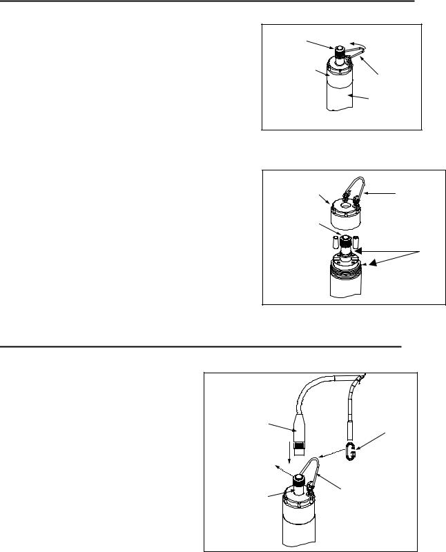
INSTALLING BATTERIES
The 6920DW and 600DW-B can also be powered by internal batteries and a set of batteries is supplied with each of these sondes. See the sections below for instructions for battery installation
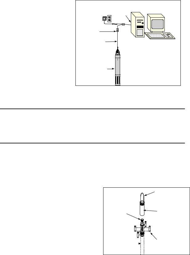
INSTALLING BATTERIES INTO THE YSI 600DW-B
To install 4 AA-size alkaline batteries into the sonde, refer to the following directions and the figure below.
Grasp the cylindrical battery cover and unscrew by hand in a counterclockwise direction. Then slide the battery lid up and over the bulkhead connector. Insert batteries, paying special attention to polarity. Labeling on the battery compartment posts describes the orientation. It is usually easiest to insert the negative end of battery first and then “pop” the positive terminal into place.
Check the O-ring and sealing surfaces for any contaminants that could interfere with the O-ring seal of the battery chamber.
Lightly lubricate the o-ring on the outside of the battery cover. DO NOT lubricate the internal o-ring.
Return the battery lid and tighten by hand.
DO NOT OVER-TIGHTEN.
|
BAIL |
|
BULKHEAD |
SCREWON |
|
CONNECTOR |
||
BATTERYCAP |
||
WITHCAP |
||
|
SONDE BODY |
|
AABATTERIES x 4 |
(NOT SHOWN) |
(NOTE POLARITY) |
|
YSI Incorporated Drinking Water Monitoring Systems Operations Manual |
2-15 |
Sondes |
Section 2 |
INSTALLING BATTERIES INTO THE 6920DW
To install the 8 AA-size alkaline batteries into the sonde, refer to the following directions and the adjacent figures.
Position the bail so that it is perpendicular to the sonde and use it as a lever to unscrew the battery cap by hand. Then slide the battery lid up and over the bulkhead connector.
Insert batteries, paying special attention to polarity. Labeling on the top of the sonde body describes the orientation.
BULKHEAD CONNECTOR
WITH CAP
BATTERY CAP
BAIL
SONDE BODY
GRASP BAIL WITH HAND.
TURN COUNTERCLOCKWISE TO LOOSEN.
F
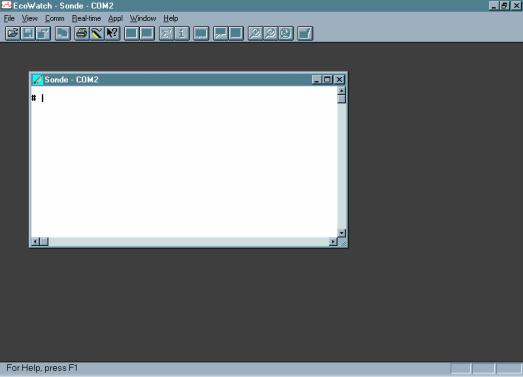
Check the O-rings and sealing surfaces for any contaminants that could interfere with the seal of the battery chamber.
Lightly lubricate the o-rings on the bottom of the threads and on the connector stem as shown in the figure at the right.
Return the battery lid and tighten by hand. DO NOT OVERTIGHTEN.
BATTERY CAP |
|
BAIL |
|
|
|
BULKHEAD |
|
|
CONNECTOR - |
+ |
O-RINGS |
+-
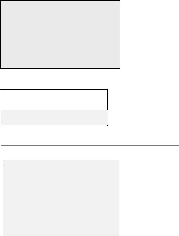
2.3.4 STEP 4 - CONNECTING A FIELD CABLE
As shown in the picture at left, the 6920DW and 600DW-B have a sonde-mounted cable connector for attachment of cables. Two types of cables are available – a “field cable” in various lengths up to 200 feet and a short 6067B laboratory calibration cable.
To attach a field cable to the sonde connector, remove the waterproof cap from the sonde connector and set it aside for later reassembly during deployment or storage. Then connect your field cable to the sonde connector.
A built-in “key” will ensure proper pin alignment. Rotate the cable gently until the “key” engages and then tighten the connectors together by rotating clockwise. Attach the strain relief connector to the sonde bail. Rotate the strain relief connector nut to close the connector's opening.
FIELD CABLE |
STRAIN RELIEF |
CONNECTOR |
CONNECTOR |
REMOVE |
|
WATERPROOF CAP |
|
SONDE |
BAIL |
|
|
CONNECTOR |
|
YSI Incorporated Drinking Water Monitoring Systems Operations Manual |
2-16 |
Sondes |
Section 2 |
The other end of the field cable is a military-style 8-pin connector (MS-8). Through use of a YSI 6095B MS-8 to DB-9 adapter, the sonde may be connected to a computer for setup, calibration, real-time measurement, and uploading files.
This MS-8 connector also plugs directly into the 650 MDS display/logger or the 6500 Process Monitor. These instruments contain microprocessors with software which provides the ability to set up and calibrate your sonde sensors in a similar way to that of a terminal interface to a PC.
As an alternative to the field cable for interface to a PC, you may use a YSI 6067B calibration cable for laboratory interaction with the sonde. In this case, simply plug the proper end of the cable into the sonde connector and attach the DB-9 connector of the cable to the Com port of your computer. Note that the 6067B will not interface to a 650 Display/Logger of 6500 Process Monitor
For drinking water studies involving only internal logging of data or real-time display of data on a PC using EcoWatch for Windows software, the 6067B may be the cable of choice.
YSI Incorporated Drinking Water Monitoring Systems Operations Manual |
2-17 |

Sondes |
Section 2 |
2.4 ECOWATCH FOR WINDOWS -GETTING STARTED
This section will describe how to get started with EcoWatch for Windows, but detailed information is provided in Section 4, EcoWatch for Windows, or a convenient Windows Help section that is part of the software. It is recommended that you thoroughly read Section 4 or use the Help function for a comprehensive understanding of EcoWatch for Windows.
2.4.1INSTALLING ECOWATCH FOR WINDOWS
EcoWatch for Windows software must be used with an IBM-compatible PC with a 386 (or better) processor. The computer should also have at least 4MB of RAM and Windows Version 3.1 or later.
Place the EcoWatch for Windows compact disk in your CD ROM drive. Select Start, then Run and type d:\setup.exe at the prompt. Press Enter or click on “OK” and the display will indicate that EcoWatch is proceeding with the setup routine. Simply follow the instructions on the screen as the installation proceeds.
2.4.2RUNNING ECOWATCH FOR WINDOWS
To run EcoWatch for Windows, simply select the EcoWatch icon on your desktop or from the Windows Program Menu. For help with the EcoWatch program, see Section 4, EcoWatch or use the Help section of the software.
2.4.3ECOWATCH FOR WINDOWS SETUP
To setup the EcoWatch software for use with a sonde, select the sonde icon  on the toolbar, and then the proper Com port (1 or 2) to which your sonde is connected. If the default setting is correct, it does not need to be changed. Click “OK” to open a terminal window.
From the Comm Menu, select the Settings option to check the baud rate. The baud rate should be 9600. If it is not, select 9600 from the list and press Enter.
From the Settings Menu, select the Font/Color and Background Color options to choose a color scheme for the EcoWatch for Windows menus.
2.5 SONDE SOFTWARE SETUP
There are two sets of software at work in any YSI environmental monitoring system. One is resident in the sonde and the other is associated with the interface device (a PC, 650 Display/Logger, or 6500 Process Monitor). If you are using a PC for your initial sonde setup as recommended, you will be using EcoWatch for Windows software which was installed as described above and you should follow the instructions in the section below to prepare your DW sonde for use. If you are using a 650 for sonde interface, see Section 5 for setup and interface instructions. If you are using a 6500 for sonde interface, see the manual which was supplied with this instrument.
YSI Incorporated Drinking Water Monitoring Systems Operations Manual |
2-18 |
Sondes |
Section 2 |
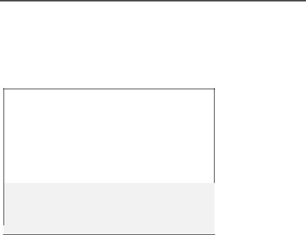
For PC-based sonde interface, run EcoWatch for Windows and click on the sonde icon,  from the toolbar Then select the proper Com port and confirm by clicking OK. A window similar to that shown below will appear indicating connection to the sonde as shown in the figure below. Type “Menu” after the
# sign, press Enter, and the sonde Main menu will be displayed.
If your sonde has previously been used, the Main menu (rather than the # sign) may appear when communication is established. In this case simply proceed as described below. You will not be required to type “Menu”.
If you are unable to establish interaction with the sonde, make sure that the cable is properly connected. If you are using external power, make certain that the YSI 6038 or 6651 power supply or other 12 vdc source is properly working. Recheck the setup of the Com port and other software parameters. Also refer to
Section 6, Troubleshooting.
The sonde software is menu-driven. You select functions by typing their corresponding numbers. You do not need to press Enter after choosing a selection. Type the 0 or Esc key to return to the previous menu.
YSI Incorporated Drinking Water Monitoring Systems Operations Manual |
2-19 |

|
Sondes |
|
|
|
Section 2 |
|
|
Sonde Main Menu |
|
|
|
|
|
|
------------------ |
|
Main----------------- |
|
|
|
|
1-Run |
5-System |
|
|
|
|
|
2-Calibrate |
6-Report |
|
|
|
|
|
3-File |
7-Sensor |
|
|
|
|
|
4-Status |
8-Advanced |
|
|
|
|
|
Select option (0 for previous menu): |
|
|
|
||
|
Sonde Menu Flow Chart |
|
|
|
|
|
|
|
|
|
|
|
|
SONDE MENU FLOW CHART |
|
|
|
|
||
|
|
Sonde |
|
|
|
|
1. |
Run |
1. Discrete sample |
|
|
1. Conductivity |
|
|
|
2. DO % |
|
|||
|
|
2. Unattended sample |
|
|
|
|
|
|
|
|
3. DO mg/L |
||
|
|
|
|
|
||
2. |
Calibrate |
|
|
|
4. Others |
|
3. |
File |
|
|
|
1. |
Directory |
Date and Time |
|
|
2. Upload |
|||
|
|
|
|
|||
|
|
Battery Voltage |
|
|
3. |
Quick Upload |
4. |
Status |
Available Memory |
1. Date & Time |
|
4. |
View File |
|
5. |
Quick View File |
||||
|
|
Logging Status |
2. Comm Setup |
|
||
|
|
|
6. |
Delete All Files |
||
|
|
|
3. Page Length |
|
||
5. |
System |
|
1. (Y) Date |
|
||
|
4. Instrument ID |
|
7. Test Memory |
|||
|
|
|
2. (Y) Time |
|
||
|
|
|
5. SDI-12 Address |
3. (Y) Temp, C |
|
|
6. |
Report |
|
|
4. ( |
) Temp, F |
|
|
|
|
MORE |
|
||
|
|
|
|
|
|
|
7. |
Sensor |
|
|
|
1. (Y) Temp |
|
|
|
|
2. |
(Y) Cond |
||
|
|
|
|
|
||
|
|
|
1. Cal Constants |
|
3. (Y) DO |
|
|
|
|
|
|
||
8. |
Advanced |
|
2. Setup |
|
4. |
( ) ISE1 pH |
|
3. Sensor |
|
|
MORE |
||
|
|
|
|
|
||
|
|
|
4. Data Filter |
|
|
|
YSI Incorporated Drinking Water Monitoring Systems Operations Manual |
2-20 |

Sondes |
Section 2 |
SYSTEM SETUP
At the Main menu, select System. The System Setup menu will be displayed.
System Setup Menu
1-Date & time
2-Comm setup
3-Page length=25
4-Instrument ID=YSI Sonde
5-Circuit board SN:00003001
6-GLP filename=00003001
7-SDI-12 address=0
8-(*)English
9-( )Fran?ais A-( )Deutsch
Select option (0 for previous menu):
Select 1-Date & time. An asterisk will appear next to each selection to confirm the entry. Press 4 and 5 to activate the date and time functions. Pay particular attention to the date format that you have chosen when entering date. You must use the 24-hour clock format for entering time. Option 4- ( ) 4 digit year may be used so that the date will appear with either a two or four digit year display. If you do not enter the correct year format (8/30/98 for 2-digit, 8/30/1998 for 4 digit) your entry will be rejected.
1------------(*)m/d/y |
Date & time setup----------- |
|
4-( )4 digit year |
||
2-( |
)d/m/y |
5-Date=08/11/98 |
3-( |
)y/m/d |
6-Time=11:12:30 |
Select option (0 for previous menu):
Select 4-Instrument ID from the System setup menu to record the instrument ID number (usually the instrument serial number), and press Enter. A prompt will appear which will allow you to type in the serial number of your sonde. This will make sure that any data that is collected is associated with a particular sonde. Note that the selection 5-Circuit Board SN shows the serial number of the PCB that is resident in your sonde (not the entire system as for Instrument ID). Unlike the Instrument ID, the user cannot change the Circuit Board SN. The 6-GLP filename and 7-SDI-12 address selections will be explained in Section 2.9.5
Press Esc or 0 to return to the System setup menu.
YSI Incorporated Drinking Water Monitoring Systems Operations Manual |
2-21 |
Sondes |
Section 2 |
At the bottom of the menu choose the language you prefer for the sonde software. For example, press 7- ( ) English to use the sonde with English menus.
1-Date & time
2-Comm setup
3-Page length=25
4-Instrument ID=YSI Sonde
5-Circuit board SN:00003001
6-GLP filename=00003001
7-SDI-12 address=0
8-(*)English
9-( )Fran?ais A-( )Deutsch
Select option (0 for previous menu):
Then press Esc or 0 again to return to the Main menu.
------------------1-Run |
-----------------Main |
5-System |
|
2-Calibrate |
6-Report |
3-File |
7-Sensor |
4-Status |
8-Advanced |
Select option (0 for previous menu):
ENABLING SENSORS
To activate the sensors that are in your sonde, select Sensor from the Sonde Main menu.
------------Sensors enabled------------
1-(*)Time
2-(*)Temperature
3-(*)Conductivity
4-(*)Free Cl2
5-(*)ISE1 pH
6-(*)ISE2 Orp
7-(*)ISE3 NH4+
8-(*)ISE4 NO3-
9-( )ISE5 NONE A-(*)Turbidity 6026
Select option (0 for previous menu):
YSI Incorporated Drinking Water Monitoring Systems Operations Manual |
2-22 |
Sondes |
Section 2 |
Note that the exact appearance of this menu will vary depending upon the sensors that are available on your sonde. Enter the corresponding number to enable the sensors that are installed on your sonde. An asterisk indicates that the sensor is enabled.
When selecting any of the ISE or Optical ports, a submenu will appear. When this occurs, make a selection so that the sensor corresponds to the port in which the sensor is physically installed. Only ORP can be enabled as ISE2. Optic T and Optic C generate a submenu on selection. Each optical port can have one of four probes (6026 turbidity, 6136 turbidity, chlorophyll, or rhodamine WT) installed as indicated by the submenus.
After all installed sensors have been enabled, press Esc or 0 to return to the Main Menu.
ENABLING PARAMETERS
In order for a specific parameter to be displayed:
1.The sensor must first be enabled as described above.
2.That parameter must be activated in the Report Setup menu described below.
Select Report from the Main menu. A Report Setup menu similar to the one shown below will be displayed.
--------------1-(*)Date |
-------------Report setup |
mV |
|
|
m/d/y |
D-(*)Orp |
|
||
2-(*)Time |
hh:mm:ss |
E-(*)NH4+ N |
mg/L |
|
3-(*)Temp |
C |
F-( )NH4+ N |
mV |
|
4-(*)SpCond mS/cm |
G-( )NH3 |
N mg/L |
||
5-( )Cond |
|
H-(*)NO3- N |
mg/L |
|
6-( )Resist |
I-( )NO3- N |
mV |
||
7-( )TDS |
|
J-(*)Cl- |
mg/L |
|
8-( )Sal ppt |
K-( )Cl- |
mV |
NTU |
|
9-(*)Cl2 mg/L |
L-(*)Turbid |
|||
A-(*)Cl2chrg |
|
|
|
|
B-(*)pH
C-( )pH mv
Select option (0 for previous menu):
Note that the exact appearance of this menu will vary depending upon the sensors that are available and enabled on your sonde. The asterisks (*) that follow the numbers or letters indicate that the parameter will appear on all outputs and reports. To turn a parameter on or off, type the number or letter that corresponds to the parameter.
Note also that since a 6026 turbidity probe was selected in the Sensor menu above, the units of turbidity are presented as “turbid NTU”. If a 6136 turbidity probe had been selected, the units of turbidity would be presented as “turbid+ NTU”. This new designation is designed to differentiate the data from the two sensors types in later analysis.
YSI Incorporated Drinking Water Monitoring Systems Operations Manual |
2-23 |
 Loading...