


 Loading...
York Commercial Comfort System
System Manager/Zone Coordinator
User’s Manual
YK-SMU2x0-0, YK-ZCU2x0-0, YK-ZCU4x0-0
YCCS System Manager / Zone Coordinator

428516-YUM-B-0908
System Manager/Zone Coordinator
User’s Manual
YK-SMU2x0-0, YK-ZCU2x0-0, YK-ZCU4x0-0
TABLE OF CONTENTS
Document Introduction . . . . . . . . . . . . . . . . . . . . . . . . . . . . . . . . . . . . . . . . . . . . . . . . . 6 Related Documentation. . . . . . . . . . . . . . . . . . . . . . . . . . . . . . . . . . . . . . . . . . . . . . . . . 6 System Manager/Zone Coordinator on the Network . . . . . . . . . . . . . . . . . . . . . . . . . 7 System Configuration . . . . . . . . . . . . . . . . . . . . . . . . . . . . . . . . . . . . . . . . . . . . . . . . . . 8 User Interface Overview . . . . . . . . . . . . . . . . . . . . . . . . . . . . . . . . . . . . . . . . . . . . . . . . 8
System Startup. . . . . . . . . . . . . . . . . . . . . . . . . . . . . . . . . . . . . . . . . . . . . . . . . . . . . . . . . . . 8
System Manager/Coordinator Menu Structure . . . . . . . . . . . . . . . . . . . . . . . . . . . . . . . . . 9
Screen Layout . . . . . . . . . . . . . . . . . . . . . . . . . . . . . . . . . . . . . . . . . . . . . . . . . . . . . . . . . . 10
Main Selection Bar. . . . . . . . . . . . . . . . . . . . . . . . . . . . . . . . . . . . . . . . . . . . . . . . . . . . . . . . 10
Title Area . . . . . . . . . . . . . . . . . . . . . . . . . . . . . . . . . . . . . . . . . . . . . . . . . . . . . . . . . . . . . . . 11
Main Display Area . . . . . . . . . . . . . . . . . . . . . . . . . . . . . . . . . . . . . . . . . . . . . . . . . . . . . . . . 11
Help Text/Paging Information Area . . . . . . . . . . . . . . . . . . . . . . . . . . . . . . . . . . . . . . . . . . . 11
Navigation Area . . . . . . . . . . . . . . . . . . . . . . . . . . . . . . . . . . . . . . . . . . . . . . . . . . . . . . . . . . 11
Enter Password Screen. . . . . . . . . . . . . . . . . . . . . . . . . . . . . . . . . . . . . . . . . . . . . . . . . . . 12
Default Passwords Provided . . . . . . . . . . . . . . . . . . . . . . . . . . . . . . . . . . . . . . . . . . . . . . . . 13
Home Screens . . . . . . . . . . . . . . . . . . . . . . . . . . . . . . . . . . . . . . . . . . . . . . . . . . . . . . . . . . 13
Display and Navigation Screens . . . . . . . . . . . . . . . . . . . . . . . . . . . . . . . . . . . . . . . . . . . 14
Data Entry Screens . . . . . . . . . . . . . . . . . . . . . . . . . . . . . . . . . . . . . . . . . . . . . . . . . . . . . . 15
Remote User Interface. . . . . . . . . . . . . . . . . . . . . . . . . . . . . . . . . . . . . . . . . . . . . . . . . . . . 16
Alarms and Alarm Priorities . . . . . . . . . . . . . . . . . . . . . . . . . . . . . . . . . . . . . . . . . . . . . . . 17
Types of Alarms . . . . . . . . . . . . . . . . . . . . . . . . . . . . . . . . . . . . . . . . . . . . . . . . . . . . . . . . . . 17
Buffer Limitation . . . . . . . . . . . . . . . . . . . . . . . . . . . . . . . . . . . . . . . . . . . . . . . . . . . . . . . . . . 18
Alarm Detection . . . . . . . . . . . . . . . . . . . . . . . . . . . . . . . . . . . . . . . . . . . . . . . . . . . . . . . . . . 18
Alarm Destinations . . . . . . . . . . . . . . . . . . . . . . . . . . . . . . . . . . . . . . . . . . . . . . . . . . . . . . 18
Pagers . . . . . . . . . . . . . . . . . . . . . . . . . . . . . . . . . . . . . . . . . . . . . . . . . . . . . . . . . . . . . . . . . 18
2 |
System Manager/Zone Coordinator User’s Manual |

428516-YUM-B-0908
E-mail Accounts . . . . . . . . . . . . . . . . . . . . . . . . . . . . . . . . . . . . . . . . . . . . . . . . . . . . . . . . . . 18
Text Messages. . . . . . . . . . . . . . . . . . . . . . . . . . . . . . . . . . . . . . . . . . . . . . . . . . . . . . . . . . . 19
Zones, Groups, and Members . . . . . . . . . . . . . . . . . . . . . . . . . . . . . . . . . . . . . . . . . . . . . 19
Event Scheduling. . . . . . . . . . . . . . . . . . . . . . . . . . . . . . . . . . . . . . . . . . . . . . . . . . . . . . . . 19
Temporary Occupancy Override . . . . . . . . . . . . . . . . . . . . . . . . . . . . . . . . . . . . . . . . . . . . . 19
All Schedules - Temporary Occupancy . . . . . . . . . . . . . . . . . . . . . . . . . . . . . . . . . . . . . . . . 20
Exception Schedules . . . . . . . . . . . . . . . . . . . . . . . . . . . . . . . . . . . . . . . . . . . . . . . . . . . . . . 20
Global and Instant Shutdown . . . . . . . . . . . . . . . . . . . . . . . . . . . . . . . . . . . . . . . . . . . . . . 20
Trend Data Collection . . . . . . . . . . . . . . . . . . . . . . . . . . . . . . . . . . . . . . . . . . . . . . . . . . . . 20
Display Units . . . . . . . . . . . . . . . . . . . . . . . . . . . . . . . . . . . . . . . . . . . . . . . . . . . . . . . . . . . 21
Maintenance Procedures . . . . . . . . . . . . . . . . . . . . . . . . . . . . . . . . . . . . . . . . . . . . . . . . . 22
Detailed Procedures . . . . . . . . . . . . . . . . . . . . . . . . . . . . . . . . . . . . . . . . . . . . . . . . . . 23
Basic Procedures. . . . . . . . . . . . . . . . . . . . . . . . . . . . . . . . . . . . . . . . . . . . . . . . . . . . . . . . 23
Waking up the Display . . . . . . . . . . . . . . . . . . . . . . . . . . . . . . . . . . . . . . . . . . . . . . . . . . . . . 23 Entering Your Password . . . . . . . . . . . . . . . . . . . . . . . . . . . . . . . . . . . . . . . . . . . . . . . . . . . 23 Logging On the Remote User Interface . . . . . . . . . . . . . . . . . . . . . . . . . . . . . . . . . . . . . . . . 24 Logging Off the Remote User Interface . . . . . . . . . . . . . . . . . . . . . . . . . . . . . . . . . . . . . . . . 24
Setup Procedures . . . . . . . . . . . . . . . . . . . . . . . . . . . . . . . . . . . . . . . . . . . . . . . . . . . . . . . 25
Setting Date and Time Parameters . . . . . . . . . . . . . . . . . . . . . . . . . . . . . . . . . . . . . . . . . . . 26 Changing the Administrator or Operator Password . . . . . . . . . . . . . . . . . . . . . . . . . . . . . . . 27 Enabling (or Disabling) Password Security . . . . . . . . . . . . . . . . . . . . . . . . . . . . . . . . . . . . . 28 Enabling (or Disabling) the Remote User Interface . . . . . . . . . . . . . . . . . . . . . . . . . . . . . . . 29 Setting up a Modem. . . . . . . . . . . . . . . . . . . . . . . . . . . . . . . . . . . . . . . . . . . . . . . . . . . . . . . 30 Specifying Ethernet Settings . . . . . . . . . . . . . . . . . . . . . . . . . . . . . . . . . . . . . . . . . . . . . . . . 31 Selecting Display Units . . . . . . . . . . . . . . . . . . . . . . . . . . . . . . . . . . . . . . . . . . . . . . . . . . . . 33 Calibrating the Display . . . . . . . . . . . . . . . . . . . . . . . . . . . . . . . . . . . . . . . . . . . . . . . . . . . . . 33 Specifying System Manager/Zone Coordinator Name. . . . . . . . . . . . . . . . . . . . . . . . . . . . . 35 Entering Job Name . . . . . . . . . . . . . . . . . . . . . . . . . . . . . . . . . . . . . . . . . . . . . . . . . . . . . . . 36
Scheduling Procedures. . . . . . . . . . . . . . . . . . . . . . . . . . . . . . . . . . . . . . . . . . . . . . . . . . . 37
Adding a Schedule. . . . . . . . . . . . . . . . . . . . . . . . . . . . . . . . . . . . . . . . . . . . . . . . . . . . . . . . 39
System Manager/Zone Coordinator User’s Manual |
3 |

428516-YUM-B-0908
Deleting a Schedule. . . . . . . . . . . . . . . . . . . . . . . . . . . . . . . . . . . . . . . . . . . . . . . . . . . . . . . 41 Adding a Member to a Schedule . . . . . . . . . . . . . . . . . . . . . . . . . . . . . . . . . . . . . . . . . . . . . 42 Deleting a Member from a Schedule . . . . . . . . . . . . . . . . . . . . . . . . . . . . . . . . . . . . . . . . . . 43 Adding an Exception Schedule . . . . . . . . . . . . . . . . . . . . . . . . . . . . . . . . . . . . . . . . . . . . . . 44 Setting up Temporary Occupancy Time . . . . . . . . . . . . . . . . . . . . . . . . . . . . . . . . . . . . . . . 45 Beginning Temporary Occupancy of a Schedule. . . . . . . . . . . . . . . . . . . . . . . . . . . . . . . . . 46 Ending Temporary Occupancy of a Schedule . . . . . . . . . . . . . . . . . . . . . . . . . . . . . . . . . . . 47 Beginning or Ending Temporary Occupancy to All Schedules . . . . . . . . . . . . . . . . . . . . . . 47
Alarm Procedures . . . . . . . . . . . . . . . . . . . . . . . . . . . . . . . . . . . . . . . . . . . . . . . . . . . . . . . 48
Configuring Pager as Alarm Destination . . . . . . . . . . . . . . . . . . . . . . . . . . . . . . . . . . . . . . . 49 Configuring E-mail Account as Alarm Destination . . . . . . . . . . . . . . . . . . . . . . . . . . . . . . . . 50 Configuring Text Message as Alarm Destination. . . . . . . . . . . . . . . . . . . . . . . . . . . . . . . . . 51 Setting Alarm Indicators. . . . . . . . . . . . . . . . . . . . . . . . . . . . . . . . . . . . . . . . . . . . . . . . . . . . 53 Viewing an Alarm Summary. . . . . . . . . . . . . . . . . . . . . . . . . . . . . . . . . . . . . . . . . . . . . . . . . 55 Deleting One or All Alarms. . . . . . . . . . . . . . . . . . . . . . . . . . . . . . . . . . . . . . . . . . . . . . . . . . 56
Summary Procedures . . . . . . . . . . . . . . . . . . . . . . . . . . . . . . . . . . . . . . . . . . . . . . . . . . . . 57
Viewing System Summaries . . . . . . . . . . . . . . . . . . . . . . . . . . . . . . . . . . . . . . . . . . . . . . . . 58
Viewing Trend Data . . . . . . . . . . . . . . . . . . . . . . . . . . . . . . . . . . . . . . . . . . . . . . . . . . . . . . . 59
Zone Setup Procedures. . . . . . . . . . . . . . . . . . . . . . . . . . . . . . . . . . . . . . . . . . . . . . . . . . . 60
Setting Up a Changeover Bypass Zone. . . . . . . . . . . . . . . . . . . . . . . . . . . . . . . . . . . . . . . . 61 Setting Up a CV RTU Zone . . . . . . . . . . . . . . . . . . . . . . . . . . . . . . . . . . . . . . . . . . . . . . . . . 62 Setting up a VAV RTU Zone . . . . . . . . . . . . . . . . . . . . . . . . . . . . . . . . . . . . . . . . . . . . . . . . 64 Editing a Zone Name . . . . . . . . . . . . . . . . . . . . . . . . . . . . . . . . . . . . . . . . . . . . . . . . . . . . . . 66 Viewing Zone Status . . . . . . . . . . . . . . . . . . . . . . . . . . . . . . . . . . . . . . . . . . . . . . . . . . . . . . 67 Copying Zone Setup to All Zones . . . . . . . . . . . . . . . . . . . . . . . . . . . . . . . . . . . . . . . . . . . . 68 Requesting Global Shutdown of all Zones in all Systems . . . . . . . . . . . . . . . . . . . . . . . . . . 69 Viewing Device Diagnostics. . . . . . . . . . . . . . . . . . . . . . . . . . . . . . . . . . . . . . . . . . . . . . . . . 70
Zoning System Setup Procedures . . . . . . . . . . . . . . . . . . . . . . . . . . . . . . . . . . . . . . . . . . 71
Setting Up a Zoning System . . . . . . . . . . . . . . . . . . . . . . . . . . . . . . . . . . . . . . . . . . . . . . . . 72
Viewing Zoning System Status . . . . . . . . . . . . . . . . . . . . . . . . . . . . . . . . . . . . . . . . . . . . . . 74
4 |
System Manager/Zone Coordinator User’s Manual |

428516-YUM-B-0908
Requesting Instant Shutdown of a Zoning System . . . . . . . . . . . . . . . . . . . . . . . . . . . . . . . 75
Balancing a Zoning System . . . . . . . . . . . . . . . . . . . . . . . . . . . . . . . . . . . . . . . . . . . . . . . . . 76
Auxiliary Points Setup Procedures . . . . . . . . . . . . . . . . . . . . . . . . . . . . . . . . . . . . . . . . . 77
Setting up Auxiliary Points . . . . . . . . . . . . . . . . . . . . . . . . . . . . . . . . . . . . . . . . . . . . . . . . . . 78 Editing an IOM Controller Name . . . . . . . . . . . . . . . . . . . . . . . . . . . . . . . . . . . . . . . . . . . . . 80 Viewing Auxiliary Points Status . . . . . . . . . . . . . . . . . . . . . . . . . . . . . . . . . . . . . . . . . . . . . . 81 Viewing IOM Controller Point Trend Data . . . . . . . . . . . . . . . . . . . . . . . . . . . . . . . . . . . . . . 82
Dial-up Communication Procedures . . . . . . . . . . . . . . . . . . . . . . . . . . . . . . . . . . . . . . . . 83
Creating a Dial-up Connection. . . . . . . . . . . . . . . . . . . . . . . . . . . . . . . . . . . . . . . . . . . . . . . 83 Dialing up a System Manager or Coordinator . . . . . . . . . . . . . . . . . . . . . . . . . . . . . . . . . . . 89
Maintenance Procedures . . . . . . . . . . . . . . . . . . . . . . . . . . . . . . . . . . . . . . . . . . . . . . . . . 90
Backing up Current Configuration . . . . . . . . . . . . . . . . . . . . . . . . . . . . . . . . . . . . . . . . . . . . 91 Restoring Configuration Information . . . . . . . . . . . . . . . . . . . . . . . . . . . . . . . . . . . . . . . . . . 92 Restoring Factory Settings. . . . . . . . . . . . . . . . . . . . . . . . . . . . . . . . . . . . . . . . . . . . . . . . . . 94 Relearning Connected Devices . . . . . . . . . . . . . . . . . . . . . . . . . . . . . . . . . . . . . . . . . . . . . . 95 Restarting the System Manager/Zone Coordinator . . . . . . . . . . . . . . . . . . . . . . . . . . . . . . . 96
System Manager/Zone Coordinator User’s Manual |
5 |

428516-YUM-B-0908
System Manager/Zone Coordinator
User’s Manual
Document Introduction
This document describes how to operate the System Manager (YK-SMU2x0-0) and Zone Coordinator (YK-ZCU2x0-0 and YK-ZCU4x0-0) with display. These products are user interface components of the York Commercial Comfort System (YCCS), which is a building automation system designed for smallto medium-sized buildings to provide occupant comfort.
Note: The term Coordinator, whenever used in this document, is shorthand for Zone Coordinator. You can also access a Coordinator without a display from a System Manager.
This document does not describe how to install the System Manager or Zone Coordinator. It also does not describe how to operate any other YCCS components.
See Related Documentation for additional information related to applying the System Manager and Zone Coordinator to your YCCS control network.
Related Documentation
Table 1: System Manager/Zone Coordinator User’s Guide Related
Documentation
For Information On |
See Document |
LIT or Part Number |
Features, Benefits, and |
York Commercial Comfort System |
428515 |
Applications of the YCCS |
Technical Guide |
|
|
|
|
Installation and Specifications |
YCCS System Manager and Zone |
428516 |
of the YCCS System Manager |
Coordinator Installation |
|
and Zone Coordinator |
Instructions |
|
6 |
System Manager/Zone Coordinator User’s Manual |
428516-YUM-B-0908
System Manager/Zone Coordinator on the Network
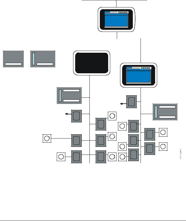
The System Manager and Zone Coordinator provide User Interfaces (UIs) to the devices in the YCCS network. The display units typically install in a main equipment or control room, and connect to the Transmission Control Protocol/Internet Protocol (TCP/IP) Ethernet network or the Master-Slave/Token-Passing (MS/TP) Bus. You can access a Coordinator without a display from a System Manager. Figure 1 shows an example of the YCCS network.
TCP/IP Ethernet
System Manager
LC-SMU-0
Thursday, May 8, 2008 |
5:23:44 PM |
Outdoor Air Temperature: |
63.1 Deg F |
Software Revision: 1.0.2445
System Bus (MS/TP)
I/O Module |
|
|
Constant Volume |
|
|
|
||||
|
|
Rooftop Controller |
|
|
|
|||||
|
|
|
|
|
|
|
|
|
|
|
|
|
|
|
|
|
|
|
|
|
|
|
|
|
|
|
|
|
|
|
|
|
|
Zone Coordinators |
|
|
LC-ZCU-10 |
|
|
Thursday, May 8, 2008 |
5:23:44 PM |
|
Zoning System Status: |
Off |
|
Outdoor Air Temperature: |
68.3 Deg F |
Zone Bus |
Software Revision: 1.0.2445 |
|
COBP Rooftop Controller (MS/TP) |
|
|
Bypass Controller
COBP Rooftop
Controller
Bypass Controller
Zone Sensors
Zone Controllers
SA Bus
Zone Sensors
Zone Sensors
Zone Controllers
Figure 1: Example of YCCS Network with System Manager and Zone Coordinators
System Manager/Zone Coordinator User’s Manual |
7 |

428516-YUM-B-0908
System Configuration
Components of the YCCS self configure as they come online. The system requires no database commissioning or programming – the System Manager detects all Coordinators on the network and displays them to the user. As the Zone Coordinator comes online to the Zone Bus network, it automatically discovers each zone and zone controller, then displays them to the user. A relearn function updates which devices are online to the Zone Bus and System Bus. During the relearn process, groups and schedules that contain any of the removed devices are also updated.
User Interface Overview
The System Manager and Zone Controller each consist of a colored Liquid Crystal Display (LCD) touch sensitive screen that you use to make all selections. No stylus pen or mouse is required. The display contains a menu-driven interface program that is stored in the embedded firmware. This program enables you to set system parameters, access system information, and monitor and control connected equipment. These operations are available from five screen types that use a common layout. The five types are the Home screen, Alarm screen, Summary screen, Schedule screen, and Setup screen. When you select a screen by touching its icon, the icon turns green, indicating that it is currently active.
System Startup
When the System Manager/Coordinator is powered on, the user interface displays a splash screen with a progress bar to indicate the status of the startup. At this point, the Alarm LED in the upper right corner of the unit is red. Seconds later, the Alarm LED turns green. Finally, the System Manager/Coordinator displays the Home screen (Figure 5 on page 13), which is the starting point for monitoring and controlling the system. The entire startup sequence takes no more than a few minutes.
8 |
System Manager/Zone Coordinator User’s Manual |
428516-YUM-B-0908
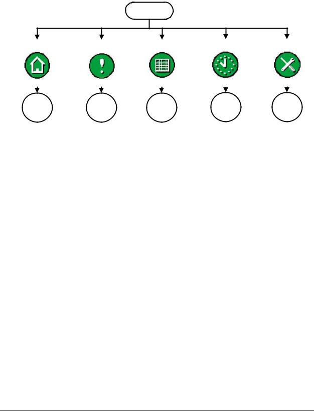
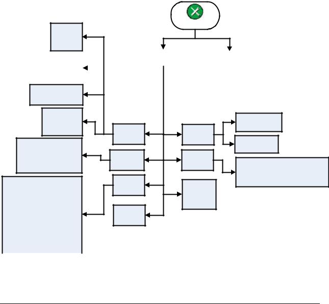
System Manager/Coordinator Menu Structure
Figure 2 is a top level flowchart of the menu structure for the System Manager/Coordinator. The menu selections are described in the following sections. See the referenced figure numbers for a detailed flowchart of the options available under each selection.
Home Screen
Home Screen |
|
Alarm Screen |
|
Summary Screen |
|
Schedule Screen |
|
Setup Screen |
|||||||||||||||
|
|
|
|
|
|
|
|
|
|
|
|
|
|
|
|
|
|
|
|
|
|
|
|
|
|
|
|
|
|
|
|
|
|
|
|
|
|
|
|
|
|
|
|
|
|
|
|
|
|
|
|
|
|
|
|
|
|
|
|
|
|
|
|
|
|
|
|
|
|
|
|
|
|
|
|
|
|
|
|
|
|
|
|
|
|
|
|
|
|
|
|
|
|
|
|
|
|
|
|
|
|
|
|
|
|
|
|
|
|
|
|
|
|
|
|
|
|
|
|
|
|
|
|
|
|
|
|
|
|
|
|
|
|
|
|
|
|
|
|
|
|
|
|
See |
|
See |
See |
See |
See |
Figure |
5. |
Figure 31. |
Figure 38. |
Figure 22. |
Figure 11. |
Figure 2: Local Controller Display Menu Structure
System Manager/Zone Coordinator User’s Manual |
9 |

428516-YUM-B-0908
Screen Layout
The screens that you access from the System Manager/Coordinator’s Home Screen share a common layout and theme. Each screen has a main selection bar, title area, main display area, help text/paging information area, and navigation area.
|
|
|
|
Main |
|
|
|
|
Selection |
|
|
|
|
Bar |
|
ZC6 - Details |
|
Title |
|
|
|
|
|
Area |
Zone Temperature: |
64.1 Deg F |
Base Setting: |
68.0 Deg F |
|
|
|
|
|
|
Zone Current Setpoint: |
62.0 Deg F |
Thermostat Alignment: |
Unavailable |
Main |
|
|
|
|
Display |
|
Unoccupied |
|
|
Area |
Occupancy Status: |
|
|
|
|
Operating Status: |
Cooling |
|
|
|
Help Text/
Zone is Requesting: None Paging Information
Area
|
|
|
|
Navigation |
Trend |
Zone Status |
Schedule |
ScrnLyt |
Area |
|
||||
|
|
Figure 3: System Manager Basic Screen Layout
Main Selection Bar
Each screen has the same main selection bar. It displays the job name (if defined) and contains the primary function icons that you push to navigate to a particular screen. The screens are Home, Alarm, Summary, Schedule, and Setup.
Table 2: Icons on Main Selection Bar
Button Description
Home icon - returns the display to the Home screen.
Alarm Summary icon - displays the Alarm summary, which is a history of alarm activity that has occurred. The alarm setup screen is also accessible from this screen. The alarm icon blinks red when a new alarm is in the system.
Summary icon - displays the Summary screen, which provides a number of summaries for the user, including trend data.
Schedule icon - displays the Schedule screen, which allows you to add, delete, and view equipment schedules.
Setup icon - displays the Setup screen, which allows you to configure the
System Manager/Coordinator and define various systems.
10 |
System Manager/Zone Coordinator User’s Manual |
428516-YUM-B-0908
Title Area
The title area shows the name of the display or edit screen and the name of the item (for example, ZC6) that is being displayed or edited.
Main Display Area
This area contains the main content for the particular screen. The area may also include touch buttons used to navigate or to display the editor screen for editing a particular parameter. This area may refresh, depending on what information appears. The normal refresh time for indicating the change in a monitored value is 5 seconds or less.
Help Text/Paging Information Area
This area displays optional help text. The text helps you understand what is displayed or how to edit a value. If the current screen is one of several pages (for example, an alarm summary), then the text Page x of y appears in this area.
Navigation Area
This area may contain one or more navigation buttons used to reach other screens. One of these buttons may be a Back button that, when pressed, displays the previous screen.
System Manager/Zone Coordinator User’s Manual |
11 |
428516-YUM-B-0908
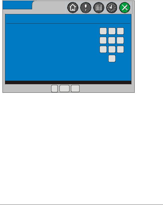
Enter Password Screen
The Password screen may appear when you attempt to change a value, request an addition, or make a deletion. The password requires 4 digits. Once the system authenticates your password entry, the screen that you requested appears.
Enter password
Enter Operator password
1 2 3
| * * * *
4 5 6
7 8 9
0
OK Cancel Clear
FIG:EntrOpPWd
Figure 4: Operator Password Entry Screen
Three user password levels are available, each with some slight differences; they are Default, Operator, and Administrator.
Table 3: Three User Password Levels
Level |
Description |
Default |
No login is required for this level. |
|
Users can view any information. The local UI assumes this level if no user |
|
is logged in. The remote UI supports this level via the Guest account. |
|
|
Operator |
Requires login with an Operator account. |
|
Allows the user to modify almost everything (except those reserved for the |
|
Administrator level.) |
|
|
Administrator |
Requires login with the Administrator password. |
|
Users can do the same actions as Operator users; plus, change |
|
passwords, restore configuration data, relearn the System or Zone bus, |
|
and disable the security feature. |
|
|
12 |
System Manager/Zone Coordinator User’s Manual |
428516-YUM-B-0908
Default Passwords Provided
Several default passwords are defined from the factory. Each is listed as follows:
Table 4: List of Default Passwords
User Name |
Default |
Privileges |
Available at: |
|
Password |
|
|
Guest |
<blank> |
View only |
Remote UI only |
|
|
|
|
Operator |
1111 |
Modify all (except |
Local and remote UI |
|
|
password) |
|
|
|
|
|
Admin |
2222 |
All privileges |
Local and remote UI |
|
|
|
|
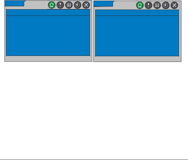
Home Screens
The Home screen appears when you first activate the System Manager or Zone Coordinator by touching its screen. This screen indicates the name and type of device, the current date and time, the software revision, and the outdoor air temperature. The Zone Coordinator Home Screen also shows Zone System Status. After 10 minutes of touch screen inactivity, the local UI times out, the user is logged out, and the screen goes to the Home screen. After 5 more minutes of inactivity (15 minutes total), the screen turns black.
System Manager Home Screen
YK-SMU-0
Thursday, May 8, 2008 5:23:44 PM
Outdoor Air Temperature: 63.1 Deg F
Zone Coordinator Home Screen
YK-ZCU-10
Thursday, May 8, 2008 5:23:44 PM
Zoning System Status: Off
Outdoor Air Temperature: 68.3 Deg F
Software Revision: 1.0.2445 |
Software Revision: 1.0.2445 |
Figure 5: Home Screens - System Manager and Zone Coordinator
Table 5 indicates the varied information for displaying the outdoor air temperature and zone system status on the Home screen. The current date, current time, outdoor air temperature, and zone system status values refresh.
Table 5: Contents of Home Screen Display
Type of Information |
Status |
What is Displayed |
Outdoor Air Temperature |
Reliable |
Current outdoor air temperature with units are shown |
|
|
|
|
Problem with |
Sensor Problem |
|
Sensor |
|
|
|
|
|
Offline |
Change-over Bypass (COB), Constant Volume (CV), or |
|
|
Variable Air Volume (VAV) Rooftop Unit (RTU) Offline |
|
|
|
|
Unavailable |
Unavailable |
|
|
|
Zoning System Status |
Online |
COB or VAV RTU status |
|
|
|
|
Offline |
COB or VAV RTU Offline |
|
|
|
FIG:HmeScrn
System Manager/Zone Coordinator User’s Manual |
13 |
428516-YUM-B-0908
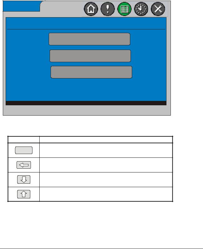
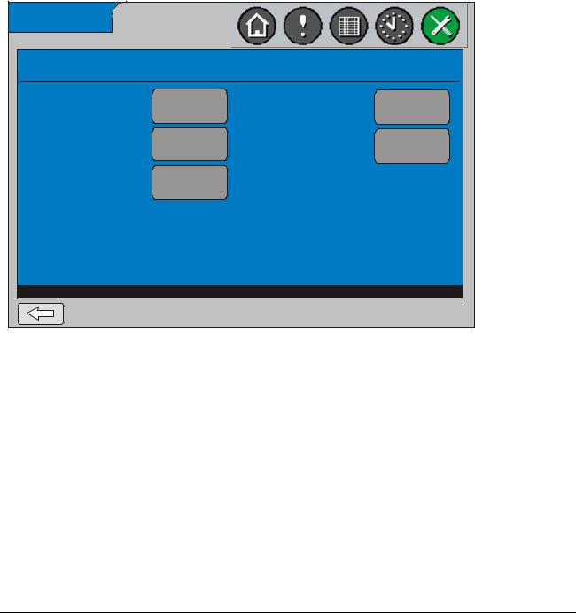
Display and Navigation Screens
Display and Navigation screens allow you to navigate through the system. By pressing the appropriate button, you find the information or reach the data input screen you need. Figure 6 is an example of a navigation screen. Table 6 describes a set of navigation buttons that may appear on any screen.
YK-SMU-0 - Setup
System Manager
Systems
Auxiliary Points
Figure 6: Example of a Navigation Screen (System Manager Setup)
Table 6: Buttons Available on Navigation Screens
Button Description
Option button - changes the display to reflect this option.
<Option>
Back button - returns the display to the previous screen.
Page Down button - displays the next page of information on this screen.
Page Up button - displays the previous page of information on this screen.
14 |
System Manager/Zone Coordinator User’s Manual |
428516-YUM-B-0908
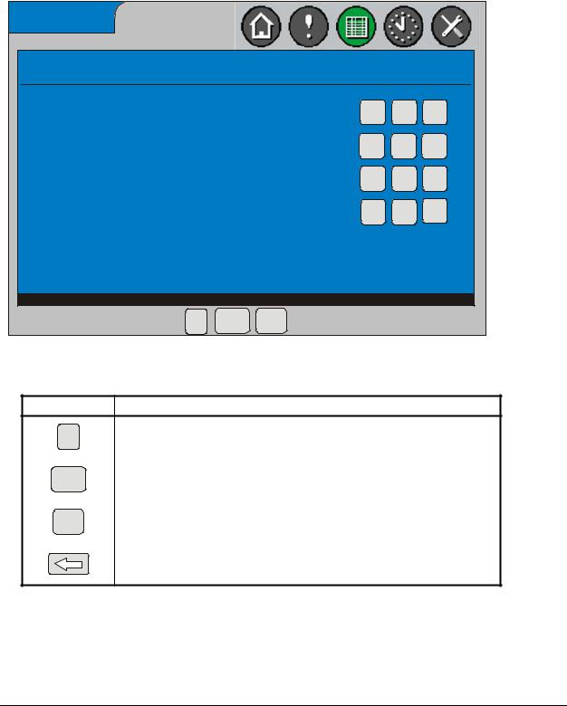
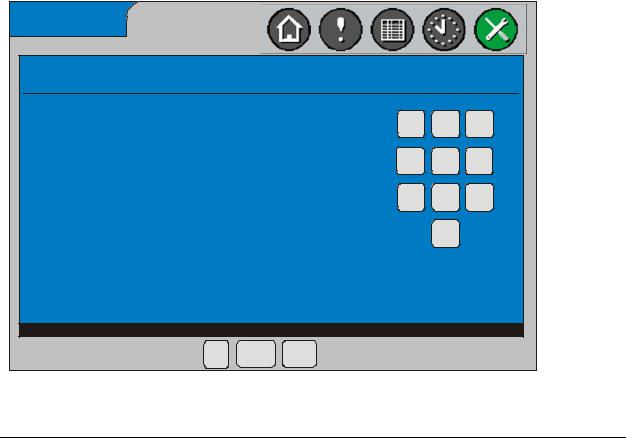
Data Entry Screens
Data Entry screens on the System Manager/Coordinator enable you to perform operations such as entering setup parameters, selecting from a list of options, and specifying time schedules. Figure 7 is an example of a screen where you can enter a scheduled occupancy time. Other data entry screens display a full keyboard. Table 7 describes the buttons that may appear in the navigation area of data entry screens.
Schedule 1 - Mon - Occupancy Time 1
Current Value: |
8:00 AM |
1 |
2 |
3 |
|
|
|||
Valid Range: |
12:00 AM to 11:29 PM |
4 |
5 |
6 |
|
|
|||
New Value: |
hh:mm AM |
7 |
8 |
9 |
|
|
|||
|
|
AM |
0 |
PM |
Enter the new time value.
OK Cancel Clear
FIG: OccTme
Figure 7: Example of a Data Entry Screen (Occupancy Time 1 Screen)
Table 7: Buttons Available on Navigation Area of Data Entry Screens
Button Description
OK |
OK button - performs the desired action. |
|
|
|
|
|
Cancel button - returns the display to the previous screen (no action is taken). |
Cancel |
|
|
|
|
Clear button - removes the data entry made in the New Value field, so that you |
Clear |
can enter a different value. |
|
|
|
Back button - returns the display to the previous screen. |
System Manager/Zone Coordinator User’s Manual |
15 |
428516-YUM-B-0908
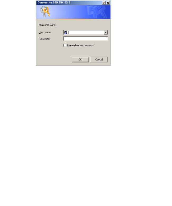
Remote User Interface
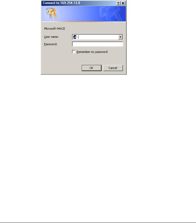
The System Manager/Coordinator includes a remote user interface option allowing you to access the device remotely using Microsoft® Internet Explorer® Web browser on your computer. You simply enter the IP address of the System Manager/Coordinator on the address bar of the browser (for example, http://169.254.13.8). A dialog box then displays, asking you to specify a valid user name and password (Figure 8).
Figure 8: Specifying User Name and Password in Browser
Most operations available locally at the System Manager/Coordinator are also available when you log on remotely. The differences between the remote UI and the local UI include the following:
•The remote UI requires you to log in with a user name and password. You can also use the default Guest account, which does not require a password and provides view-only access to the system. The Guest access level is the equivalent of a local user prompting the UI by pressing the touch screen.
•You can disable remote system access; see Enabling (or Disabling) the Remote User Interface.
•You cannot disable the use of security on the remote UI.
•The remote UI time-out due to user inactivity does not log you out; remote UI log out only occurs when you close the browser.
•The data refresh rate of the remote UI is between 5 and 10 seconds.
•The remote UI does not display the numeric keypad because you use the computer keyboard to enter values into parameter fields or the mouse to select from drop-down dialog boxes.
•The remote UI does not use the Back Arrow or the Up/Down Arrow buttons; you use the browser’s Back button to display the previous screen and the scroll bar to move up and down the screen.
16 |
System Manager/Zone Coordinator User’s Manual |

428516-YUM-B-0908
Note: The user name and password screen in Figure 8 may also appear whenever you are logged on to the System Manager/Coordinator and access an operation, which requires user authentication such as changing your password. After you enter your password, you do not need to enter it again during the session, unless you request an operation that requires a higher level password.
Note: All screen representations in this document reflect how they appear at the display, not how they appear at the remote interface.
Alarms and Alarm Priorities
The System Manager and Zone Coordinator monitor the status of equipment on the network and report an alarm whenever they detect a problem has occurred such as an offline condition. The following information is gathered for each alarm:
•Name of the device the alarm is associated with
•Alarm condition
•Date and time when the condition occurred
•Suggested user action
•Priority of alarm, which can be one of the following:
•Service - service whenever convenient
•Service Priority - service is required as soon as possible
•Critical - service is required immediately
Types of Alarms
The Zone Coordinator generates an alarm for each new problem condition, such as:
•Offline transitions of the COB or VAV Rooftop Unit (RTU) Controller, Bypass Damper Controller and Zone Controllers on its Zone Bus
•Online transitions of the COB or VAV RTU Controller, Bypass Damper Controller and Zone Controllers on its Zone Bus
•Mechanical equipment problems detected by a COB or VAV RTU Controller Similarly, the System Manager generates an alarm for:
•Offline transitions of the COB or VAV RTU Controller, IOM Controllers and Coordinators on its System Bus
•Online transitions of the COB or VAV RTU Controller, IOM Controllers and Coordinators on its System Bus
•Mechanical equipment problems detected by a CV RTU, COB RTU or VAV RTU Controller
System Manager/Zone Coordinator User’s Manual |
17 |

428516-YUM-B-0908
Buffer Limitation
The Zone Coordinator holds the last 50 alarms in memory, whereas the System Manager keeps the last 150 alarms. When the buffer limit is reached, the newest alarm replaces the oldest alarm. All alarms kept at the Coordinator are also forwarded to the System Manager. If the Coordinator cannot forward the alarms to the System Manager, the last 50 alarms are kept at the Coordinator, then sent within 30 seconds after communication between the two devices has been restored.
Alarm Detection
When a new alarm occurs, the Alarm icon on the display turns red and begins to blink. Also, the Alarm LED on the upper right corner of the display turns from green to red. The Alarm icon returns to its normal state and the Alarm LED returns to green after you select the Alarm icon at the System Manager or Coordinator.
You can view alarms by pressing the Alarm icon from the Home screen. The most recent alarms are listed first. After you view the alarms in the system, you can delete them, either one at a time or all alarms at once.
Alarms can be routed to pagers, e-mail accounts, and cell phones via text messaging. See Alarm Destinations on page 18 for details.
Alarm Destinations
The System Manager and Coordinator may send alarms to destinations such as pagers, e-mail accounts, and cellular phones with text messaging systems. By default, the System Manager or Coordinator routes any critical alarm to these destinations, but only if you have configured the destinations. An analog telephone line and a System Manager or Zone Controller with an internal modem is required for sending alarms to pagers.
An Ethernet connection is required for sending alarms to e-mail accounts and text messaging systems. A text messaging system is any software application that routes text messages to cellular phones that support the Short Message Service (SMS) protocol. To increase alarm coverage, you may choose all three alarm destinations on a single System Manager and Coordinator.
The following is an example of an alarm sent to an alarm destination:
6/5/2008 1:04:28 AM ZC7 On-line 189 Communications Restored - Service
Pagers
The System Manager or Coordinator can send alarms to paging devices. When a critical alarm occurs, the internal modem in the device uses the pager configuration parameters to establish communication with the paging system. The device passes the alarm to the paging system, then routes it to the pager. The time required for the alarm text to reach the pager depends on several factors, including the speed and reliability of the paging service.
E-mail Accounts
The System Manager or Coordinator can send alarms to e-mail accounts. When a critical alarm occurs, the device constructs a message with an e-mail format, then sends it
18 |
System Manager/Zone Coordinator User’s Manual |

428516-YUM-B-0908
over the active Internet connection to the Simple Mail Transfer Protocol (SMTP) server using the configured e-mail destination parameters. The SMTP server passes the message into the e-mail account specified. The time required for the alarm text to reach an e-mail Inbox depends on several factors, which include the speed and availability of the e-mail server.
Text Messages
The System Manager or Coordinator can send alarms to cellular phones that use the SMS protocol. When a critical alarm occurs, the device constructs a message with an SMS format, then sends it over the active Internet connection to the SMS server using the configured text message destination parameters. The SMS server sends the message to the subscriber’s cellular phone account. The time required for the alarm text to reach a cellular phone depends on several factors, including the speed and availability of the service provider.
Zones, Groups, and Members
A Zone is an area of the building where temperature is under the control of a single Zone Controller. A small office, classroom, warehouse, or gymnasium can be considered one zone.
A Group is a collection of zones that operate on the same schedule or temporary occupancy state. Each group can support up to 24 zones for COB RTU systems or 32 zones for VAV RTU systems. Each Coordinator can control up to 4 groups.
Lastly, a Member is something you can schedule, which can be a Group, CV RTU, or IOM output point. The Member List is the screen that shows the currently defined members.
Event Scheduling
You can define up to 24 event schedules at the System Manager and up to 4 event schedules on the Zone Coordinator, if the Zone Coordinator is not reporting to a System Manager. Each schedule consists of a unique schedule name and a pair of two occupied times and two unoccupied times for each day of the week. Each schedule also has one or more members. A member is something that can be scheduled.
The last commanded state by a schedule for a particular day rolls over into the next day (that is, remains the same) until the next commanded state for the new day occurs. If the Coordinator reports to a System Manager, the Coordinator scheduling is not used. In this case, the System Manager defines and executes all Coordinator schedules.
Temporary Occupancy Override
Temporary Occupancy Override allows you to force a group of zones into a temporarily occupied state for a period of time, called the time-out delay. You can do this from the Zone Details screen or by pushing the temporary occupancy button on the thermostat. This action causes the zone, and all other zones in the same Group, to become temporarily occupied together. The system ignores all occupancy schedules for these zones during the time-out period. Once the time-out delay expires, the zones return to their normal occupancy schedule.
System Manager/Zone Coordinator User’s Manual |
19 |

428516-YUM-B-0908
You can also force a single schedule, or all schedules, into the temporary occupancy state from the UI. This action places all members of the schedule into temporary occupancy. Members of the schedule can be a Group of zones or one or more CV RTUs. Again, when the time-out period expires, the members return to their normal occupancy schedule.
You can change the temporary occupancy time-out delay. Its range is from 15 to 240 minutes, with a default value of 120 minutes. You can also cancel temporary occupancy at any time from the UI.
To indicate which schedules (if any) are temporarily occupied, view the Schedules Summary on the System Manager or Coordinator. The Zone Status screen indicates whether a particular zone is temporarily occupied.
All Schedules - Temporary Occupancy
This option places all schedules under temporary occupancy. This function is the same as if just one schedule was under temporary occupancy. The same duration applies: 15 to 240 minutes.
Exception Schedules
You can add exception schedules throughout the year to accommodate holidays and other periods of time that require different scheduling. Each exception schedule can be for a single or reoccurring event, such as once every year. The exception replaces the complete weekly schedule for the day it is active. Two sets of occupied and unoccupied times can be defined per exception schedule.
Global and Instant Shutdown
The Global Shutdown function shuts down the entire system from the System Manager. This command shuts down all Coordinators and CV RTUs that report to the System Manager. An enable function is also available to re-enable the entire system.
The Instant Shutdown function shuts down a single Coordinator, CV RTU, or IOM. Shutting down a coordinator also shuts down all of its zones. An enable function is also available to re-enable a single system.
Trend Data Collection
The System Manager and Coordinator keep records of the changing values of points in the system. You can view these values on a Trend report. The System Manager or Coordinator collects one sample every 15 minutes over the past 72 hours for the following values:
•Zone temperature
•Supply or discharge air temperature
•Return air temperature
•Outside air temperature
20 |
System Manager/Zone Coordinator User’s Manual |
428516-YUM-B-0908
The System Manager and Coordinator also collect samples for the last 10 changes of the following outputs:
•RTU fan status (On/Off)
•Cool1 to Cool4 (On/Off)
•Heat1 to Heat3 (On/Off)
You can view this data in tabular format sorted by time and date, with the most current samples listed first. The data that is displayed for each sample includes:
•Time and Date
•Trended value
•Units (if the trended value is an analog value)
The trend information is current at the time you requested the data. The System Manager or Coordinator replaces old trend data with the newest data as it becomes available. The trend data cannot be printed or exported. Also, the data does not refresh dynamically as it is viewed.
Display Units
The user interface can display data using the English or Metric format. Table 8 shows the analog value units. These units apply wherever the value is displayed or modified. You can specify which system of units to use for the site; see Selecting Display Units on page 33.
Table 8: Display Units on User Interface
Type |
English Units |
Metric Units |
No. of Decimal Places |
CO2 |
ppm |
ppm |
0 |
Damper Position |
% |
% |
0 |
|
|
|
|
Pressure |
in wc |
Pa |
2 for in wc |
|
|
|
0 for Pa |
|
|
|
|
Relative Humidity |
% |
% |
0 |
|
|
|
|
Temperature |
Deg F |
Deg C |
1 |
|
|
|
|
Time |
hh:mm AM or PM |
hh:mm AM or PM |
n/a |
|
|
|
|
System Manager/Zone Coordinator User’s Manual |
21 |

428516-YUM-B-0908
Maintenance Procedures
The System Manager/Zone Coordinator includes the following maintenance procedures available to the operator:
•Backup/Restore Configuration - copies the existing configuration (or restores a backed up configuration) using a connected Universal Serial Bus (USB) drive.
•Restore Factory Settings - replaces the configuration parameters currently stored in the System Manager/Zone Coordinator with the original factory defaults.
•Relearn Connected Devices - removes any offline Coordinators, CV RTUs, or IOMs at the System Manager or zones at the Coordinator. If a device comes back online later, it reappears in the device summary.
•Restart System Manager/Zone Coordinator - performs a general restart of the device.
22 |
System Manager/Zone Coordinator User’s Manual |
428516-YUM-B-0908
Detailed Procedures
Basic Procedures
Basic procedures include waking up the display, entering your password, and logging on/logging off the remote user interface.
Waking up the Display
To wake up the System Manager/Coordinator when its display is dark, simply press your finger to the display. The Home screen appears (Figure 5 on page 13). The display remains active until 10 minutes of no user activity. After 10 minutes, you are logged off automatically and the Home screen returns. Then, after another 5 minutes of inactivity, the screen goes to sleep (goes dark).
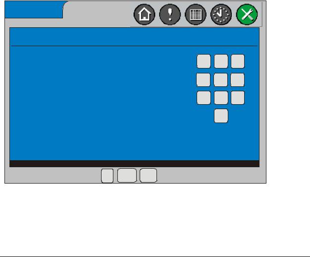
Entering Your Password
To enter your password:
1.Use the number keypad on the display to enter your four digit password (Figure 9). The password screen displays whenever you attempt an operation that requires user authentication. Asterisks appear as you select each number. If you type an incorrect number, press Clear, then reenter the full password.
Enter Operator password
1 2 3
| * * * *
4 5 6
7 8 9
0
Enter password
OK Cancel Clear
Figure 9: Operator Password Entry Screen
FIG:EntrOpPWd
2. Press OK to submit your password. The screen you requested appears.
System Manager/Zone Coordinator User’s Manual |
23 |
428516-YUM-B-0908
Logging On the Remote User Interface
To log on the remote user interface:
1.Open your Internet browser and type the IP address of the System Manager/ Coordinator in the address bar. Example:
http://192.254.12.3
2.Press Enter. A dialog box then displays prompting for a valid user name and password (Figure 10).
Figure 10: Specifying User Name and Password in Browser
3.Type your user name and password and click OK. The Home screen of the System Manager/Coordinator appears.
Logging Off the Remote User Interface
To log off the remote user interface, simply close your browser. There is no log off button or option available.
Note: The remote user interface does not timeout the user based on inactivity. The session is active until the browser displays a different Web page or you close the browser.
24 |
System Manager/Zone Coordinator User’s Manual |
428516-YUM-B-0908
Setup Procedures
Setup procedures include:
•Setting date and time parameters
•Changing the administrator or operator password
•Enabling/disabling the password requirement and remote user interface
•Setting up the modem
•Specifying Ethernet settings
•Selecting display units
•Calibrating the touch screen
•Specifying system manager name, zone coordinator name, and job name
Figure 11 is a flowchart of the Setup menu structure for the System Manager and Zone Coordinator. These menu selections are described in the sections that follow.
Setup
Change
Operator
Password
|
|
|
|
System |
|
|
|
|
|
|
|
Zone |
|
Change |
|
|
|
|
||
|
|
|
Manager |
|
Coordinator |
|
Administrator |
|
|
|
|
|
(See following Note.) |
|
|
|
|
|
||
Password |
|
|
|
|
|
|
|
|
|
|
|
|
|
Enable/Disable
Security (Password)
Enable/Disable |
|
|
Calibrate Touch |
|
Remote User |
|
|
||
|
|
|
Screen |
|
Interface |
Security |
Display |
|
|
|
|
|||
|
|
|
||
• Daylight Savings Time |
(password) |
Setup |
• |
Display Units |
|
|
|||
• Current Date |
|
|
• Language |
|
• Current Time |
Time |
Modem |
|
|
• Time Zone |
Management |
Setup |
• Allow Incoming Connections |
|
• Time Display |
|
|
• Baud Rate |
|
• DHCP Enabled |
Ethernet |
|
• |
Wait for Dial Tone Before Dialing |
System |
• |
Extra Initialization Commands |
||
• Obtain DNS Address |
Setup |
|
|
|
Manager/ |
|
|
||
Automatically |
|
|
|
|
|
Coordinator |
|
|
|
• Ethernet MAC Address |
|
|
|
|
|
Name |
|
|
|
• Computer Name |
|
|
|
|
|
|
|
|
|
• Domain Name |
Job Name |
|
|
|
• IP Address |
|
|
|
|
• IP Mask |
|
|
|
|
• IP Router Address |
Note: If you perform Zone Coordinator setup from a System Manager, some |
|
• |
1st DNS Server IP Address |
selections are not available because they are under the control of the System |
• |
2nd DNS Server IP Address |
Manager or are operations only done locally at the Coordinator. They include |
|
|
Time Management, Display Setup, Alarm Setup, Security (Password), and Job |
|
|
|
|
|
Name. |
FIG:StupFlw
Figure 11: Setup Options - Menu Structure
System Manager/Zone Coordinator User’s Manual |
25 |
428516-YUM-B-0908
Setting Date and Time Parameters
To set date and time parameters:
1.From the Home screen, press the Setup icon. The System Manager Setup or Coordinator Setup and Status screen appears.
2.For a System Manager, press the System Manager button. The System Manager Setup screen appears.
For a Coordinator, press the Coordinator button. The Coordinator Setup screen appears.
3.Press the Time Management button. The Time Management screen appears.
Time Management
Daylight Savings Time: |
Enabled |
Time Zone: |
Central |
Current Date: |
May 6, 2008 |
Current Time: |
12:47 PM |
|
|
||
Time Display: |
12-Hour |
|
|
|
|
|
|
|
Format |
|
|
Select value to modify.
Figure 12: Time Management Screen
FIG:TmeMgtScrn
4.Press the button for the time parameter you want to change. The button label describes the current setting. When you press the button, the appropriate screen appears allowing you to change the value. Table 9 lists these parameters and their ranges or possible selections.
Table 9: Time Management Parameters
Parameter |
Parameter Range/Selections |
Current Date |
Month: January to December |
|
Date: 1 to 31 |
|
Year: 2001 to 2099 |
|
|
Current Time |
12:00 AM to 12:00 PM |
|
|
Daylight Savings Time |
Enabled or Disabled |
|
|
Time Display |
12-hour format or 24-hour format |
|
|
Time Zone |
Eastern, Central, Mountain, Pacific |
|
|
26 |
System Manager/Zone Coordinator User’s Manual |
428516-YUM-B-0908
5.Make the time parameter changes and press OK. The Time Management screen returns, reflecting the changes you made.
Changing the Administrator or Operator Password
To change the administrator or operator password:
1.From the Home screen, press the Setup icon. The System Manager Setup or Coordinator Setup and Status screen appears.
2.For a System Manager, press the System Manager button. The System Manager Setup screen appears.
For a Coordinator, press the Coordinator button. The Coordinator Setup screen appears.
3.Press the Security (password) button. The Security/Password Setup screen appears.
4.To change the administrator password, press the Change Administrator Password button. If you are not currently logged in as the Administrator, the Enter Administrator Password screen appears. Enter the Administrator password to continue. After the password is verified, the Change Administrator Password screen appears.
To change an operator password, press the Change Operator Password button. If you are not currently logged in as the Administrator, the Enter Administrator Password screen appears. Enter the Administrator password to continue. After the password is verified, the Change Administrator Password screen appears.
Change Operator Password
1 2 3
New Password: |
| |
4 5 6
Confirm Password:
7 8 9
0
Enter new 4 digit password.
OK Cancel Clear
FIG:ChngPwd
Figure 13: Password Definition Screen
System Manager/Zone Coordinator User’s Manual |
27 |
428516-YUM-B-0908
5.Use the number keypad to specify a new password. Use any combination of 4 digits. Press the Clear button if you need to erase the digits and start over.
As you enter the password, asterisks appear in the New Password field.
6.To confirm, reenter the new password in the Confirm Password field.
7.Press OK to submit the new password. The Security/Password Setup screen returns.
Enabling (or Disabling) Password Security
To enable (or disable) password security:
Note: This function is only available at the System Manager (or Coordinator). You cannot perform this procedure from the remote user interface.
1.From the Home screen, press the Setup icon. The System Manager Setup or Coordinator Setup and Status screen appears.
2.For a System Manager, press the System Manager button. The System Manager Setup screen appears.
For a Coordinator, press the Coordinator button. The Coordinator Setup screen appears.
3.Press the Security (password) button. The Security/Password Setup screen appears.
4.Press the Security (Password) button. The Security (Password) screen appears.
Security (Password)
Curent Value:
Enabled
New Value:
Disabled
OK Cancel
Figure 14: Security (Password) Screen
FIG:PwdEna
28 |
System Manager/Zone Coordinator User’s Manual |
428516-YUM-B-0908
5.To disable password security when the password requirement is currently enabled, press OK.
To enable password security when the password requirement is currently disabled, press OK.
The Security/Password Setup screen returns, indicating the password security change you made.
Enabling (or Disabling) the Remote User Interface
To enable (or disable) the remote user interface:
Note: This function is only available at the System Manager (or Coordinator). You cannot perform this procedure from the remote user interface.
1.From the Home screen, press the Setup icon. The System Manager Setup or Coordinator Setup and Status screen appears.
2.For a System Manager, press the System Manager button. The System Manager Setup screen appears.
For a Coordinator, press the Coordinator button. The Coordinator Setup screen appears.
3.Press the Security (password) button. The Security/Password Setup screen appears.
4.Press the Remote User Interface button. The Remote User Interface screen appears.
Remote User Interface
Curent Value:
Enabled
New Value:
Disabled
OK Cancel
Figure 15: Remote User Interface Screen
FIG:RmtUsrIntrfc
System Manager/Zone Coordinator User’s Manual |
29 |
Loading...