


 Loading...
MILLENNIUM TM
CENTRIFUGAL LIQUID CHILLERS
OPERATING & MAINTENANCE |
Supersedes: Nothing |
Form 160.49-O2 (1296) |
|
|
|
MODEL YK M3 M3 G4 THRU YK S6 S4 J2 (STYLE C)
R-22 (COOLING ONLY)
MODEL YK LB LB G4 THRU YK SE SC J4 (STYLE C)
R-134a (COOLING ONLY)
WITH MICROCOMPUTER CONTROL CENTER
PART #371-01200-010, 371-01200-011 & 371-01200-015
FOR ELECTRO-MECHANICAL STARTER,
SOLID STATE STARTER & VARIABLE SPEED DRIVE
27385A
W ARNING
SYSTEM CONTAINS REFRIGERANT UNDER PRESSURE.
SERIOUS INJURY COULD RESULT IF PROPER PROCEDURES ARE NOT
FOLLOWED WHEN SERVICING SYSTEM. ALL SERVICE WORK SHALL
BE PERFORMED BY A QUALIFIED SERVICE TECHNICIAN IN ACCOR-
DANCE WITH YORK INSTALLATION/OPERATION MANUAL.
|
|
TABLE OF CONTENTS |
|
|
|
|
Page |
SECTION 1 |
– Description of System and |
|
|
|
|
Fundamentals of Operation ......................................... |
4 |
SECTION 2 |
– |
MicroComputer Control Center ...................................... |
6 |
SECTION 3 |
– |
System Operating Procedures ..................................... |
30 |
SECTION 4 |
– |
System Component Description .................................. |
37 |
SECTION 5 |
– |
Operational Maintenance ............................................. |
42 |
SECTION 6 |
– |
Trouble Shooting ........................................................... |
44 |
SECTION 7 |
– |
Maintenance ................................................................. |
49 |
SECTION 8 |
– |
Preventive Maintenance ............................................... |
58 |
REFERENCE INSTRUCTIONS
DESCRIPTION |
FORM NO. |
|
|
Solid State Starter – Operation & Maintenance |
160.46-OM3.1 |
Variable Speed Drive – Operation |
160.00-O1 |
Installation |
160.49-N5 |
Installation and Operation of Printers |
160.49-N7 |
Wiring Diagram – Unit with Electro-Mechanical Starter |
160.49-PW7 |
Wiring Diagram – Field Connections (E-M Starter) |
160.49-PW10 |
Wiring Diagram – Field Control Modifications |
160.49-PW13 |
Wiring Diagram – Control Center with SS Starter |
160.49-PW8 |
Wiring Diagram – Field Connections (SS Starter) |
160.49-PW11 |
Wiring Diagram – Solid State Starter |
160.49-PW14 |
Wiring Diagram – Unit with Solid State Starter |
160.49-PW8 |
Wiring Diagram – Unit with Variable Speed Drive |
160.49-PW9 |
Wiring Diagram – Field Connections (V.S.D.) |
160.49-PW12 |
Wiring Diagram – Variable Speed Drive |
160.49-PW15 |
|
|
2 |
YORK INTERNATIONAL |

FORM 160.49-O2
NOMENCLATURE
R-22 UNITS
YK N2 N1 H1 – CX C
|
|
|
|
|
|
|
|
|
|
|
|
|
|
|
|
|
|
|
|
|
|
|
|
DESIGN LEVEL (C) |
|
|
|
|
|
|
|
|
|
|
|
|
|
|
|
|
|
|
|
|
|
|
|
|
|
|
|
|
|
|
|
|
|
|
|
||
|
|
|
|
|
|
|
|
|
|
|
|
|
|
|
|
|
|
|
|
|
|
|
|
|
{ |
|
|
|
|
|
|
|
|
|
|
|
|
|
|
|
|
|
|
|
|
|
|
|
|
|
|
|
|
|
|
|
MOTOR CODE: |
|
|||
|
|
|
|
|
|
|
|
|
|
|
|
|
|
|
|
|
|
|
|
|
|
|
|
|
60 HZ |
50 HZ |
||||
|
|
|
|
|
|
|
|
|
|
|
|
|
|
|
|
|
|
|
|
|
|
|
POWER SUPPLY |
CH |
CX |
5CE |
|
5CT |
||
|
|
|
|
|
|
|
|
|
|
|
|
|
|
|
|
|
|
|
|
|
|
|
||||||||
|
|
|
|
|
|
|
|
|
|
|
|
|
|
|
|
|
|
|
|
|
|
|
– for 60 HZ |
CJ |
CY |
5CF |
|
5CU |
||
|
|
|
|
|
|
|
|
|
|
|
|
|
|
|
|
|
|
|
|
|
|
|
CK |
CZ |
5CG |
|
5CV |
|||
|
|
|
|
|
|
|
|
|
|
|
|
|
|
|
|
|
|
|
|
|
|
|
5 for 50 HZ |
|
||||||
|
|
|
|
|
|
|
|
|
|
|
|
|
|
|
|
|
|
|
|
|
|
|
CL |
CA |
5CH |
|
5CW |
|||
|
|
|
|
|
|
|
|
|
|
|
|
|
|
|
|
|
|
|
|
|
|
|
|
|
|
|
||||
|
|
|
|
|
|
|
|
|
|
|
|
|
|
|
|
|
|
|
COMPRESSOR CODE |
CM |
CB |
5CI |
|
5CX |
||||||
|
|
|
|
|
|
|
|
|
|
|
|
|
|
|
|
|
|
|
CN |
DA |
5CJ |
|
5DA |
|||||||
|
|
|
|
|
|
|
|
|
|
|
|
|
|
|
|
|
|
|
|
|
G4, H0, H1, H2, J1, J2 |
|
||||||||
|
|
|
|
|
|
|
|
|
|
|
|
|
|
|
|
|
|
|
|
|
CP |
DB |
5CK |
|
5DB |
|||||
|
|
|
|
|
|
|
|
|
|
|
|
|
|
|
|
|
|
|
|
|
|
|
|
|
|
CR |
DC |
5CL |
|
5DC |
|
|
|
|
|
|
|
|
|
|
|
|
|
|
|
CONDENSER CODE |
CS |
DD |
5CM |
|
5DD |
||||||||||
|
|
|
|
|
|
|
|
|
|
|
|
|
|
|
||||||||||||||||
|
|
|
|
|
|
|
|
|
|
|
|
|
|
|
|
|
M3, M4, N3, N4, P3, P4, Q3, Q4, R3, R4, S3, S4 |
CT |
DE |
5CN |
|
5DE |
||||||||
|
|
|
|
|
|
|
|
|
|
|
|
|
|
|
|
|
|
|
|
|
|
|
|
|
|
CU |
DF |
5CO |
|
5OF |
|
|
|
|
|
|
|
|
|
|
|
COOLER CODE |
CV |
DH |
5CP |
|
5OG |
||||||||||||||
|
|
|
|
|
|
|
|
|
|
|
||||||||||||||||||||
|
|
|
|
|
|
|
|
|
|
|
CW |
DJ |
5CQ |
|
5OH |
|||||||||||||||
|
|
|
|
|
|
|
|
|
|
|
|
|
M3, M4, N3, N4, P3, P4, P5, P6, Q3, Q4, Q5, Q6, |
|
||||||||||||||||
|
|
|
|
|
|
|
|
|
|
|
|
|
|
|
5CR |
|
5OJ |
|||||||||||||
|
|
|
|
|
|
|
|
|
|
|
|
|
R3, R4, R5, R6, S5, S6 |
|
|
|
||||||||||||||
|
|
|
|
|
|
|
|
|
|
|
|
|
|
|
5CS |
|
|
|||||||||||||
|
|
|
|
|
|
|
|
|
|
|
|
|
|
|
|
|
|
|
|
|
|
|
|
|
|
|
|
|
|
|
|
|
|
|
|
|
MODEL |
|
|
|
|
|
|||||||||||||||||||
|
|
|
|
|
|
|
|
|
|
|
||||||||||||||||||||
R-134a
YK NB PB H1 – CX C
DESIGN LEVEL (C)
POWER SUPPLY
– for 60 HZ 5 for 50 HZ
COMPRESSOR CODE
G4, H0, H1, H2, J1, J2, J3, J4
CONDENSER CODE
LB, LC, MB, MC, NB, NC,
PB, PC, QB, QC, RB, RC, SB, SC
COOLER CODE
LB, LC, MB, MC, NB, NC, PB, PC, PD, PE,
QB, QC, QD, QE, RB, RC, RD, RE, SD, SE
MODEL
{ |
|
MOTOR CODE: |
|
||
60 HZ |
50 HZ |
||||
|
CH |
CX |
5CE |
|
5CT |
|
CJ |
CY |
5CF |
|
5CU |
|
CK |
CZ |
5CG |
|
5CV |
|
CL |
CA |
5CH |
|
5CW |
|
CM |
CB |
5CI |
|
5CX |
|
CN |
DA |
5CJ |
|
5DA |
|
CP |
DB |
5CK |
|
5DB |
|
CR |
DC |
5CL |
|
5DC |
|
CS |
DD |
5CM |
|
5DD |
|
CT |
DE |
5CN |
|
5DE |
|
CU |
DF |
5CO |
|
5DF |
|
CV |
DH |
5CP |
|
5DG |
|
CW |
DJ |
5CQ |
|
5DH |
|
|
|
5CR |
|
5OJ |
|
|
|
5CS |
|
|
YORK INTERNATIONAL |
3 |
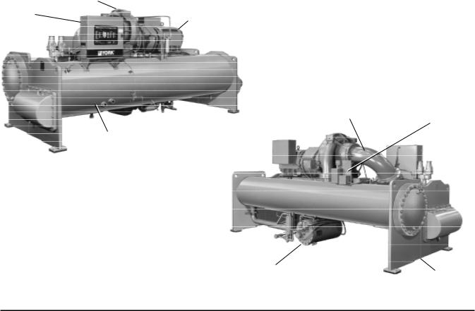
SECTION 1
DESCRIPTION OF SYSTEM AND FUNDAMENTALS OF OPERATION
|
COMPRESSOR |
CONTROL |
|
CENTER |
MOTOR |
|
PRE-ROTATION
DISCHARGE LINE VANE ACTUATOR
27385A
COOLER
|
27382A |
OIL RESERVOIR/ |
CONDENSER |
PUMP |
FIG. 1 – MODEL YK MILLENNIUM CHILLER
SYSTEM OPERATION DESCRIPTION (See Fig. 2)
The YORK Model YK Millennium Chiller is commonly applied to large air conditioning systems, but may be used on other applications. The chiller consists of an open motor mounted to a compressor (with integral speed increasing gears) condenser, cooler and flow control chamber.
The chiller is controlled by a modern state of the art MicroComputer Control Center which monitors its operation. The Control Center is programmed by the operator to suit job specifications. Automatic timed startups and shutdowns are also programmed to suit nighttime, weekends, and holidays. The operating status, temperatures, pressures, and other information pertinent to operation of the chiller are automatically displayed and read on a 40 character alphanumeric message display. Other displays can be observed by pressing the keys as labeled on the Control Center. The chiller with the MicroComputer Control Center is applied with an electro-mechanical starter, YORK Solid State Starter (optional), or Variable Speed Drive (optional).
In operation, a liquid (water or brine to be chilled) flows through the cooler, where boiling refrigerant absorbs heat from the water. The chilled liquid is then piped to fan coil units or other air conditioning terminal units, where it flows through finned coils, absorbing heat from the air. The warmed liquid is then returned to the chiller to complete the chilled liquid circuit.
The refrigerant vapor, which is produced by the boiling action in the cooler, flows to the compressor where the rotating impeller increases its pressure and temperature and discharges it into the condenser. Water flowing through the condenser tubes absorbs heat from the refrigerant vapor, causing it to condense. The condenser water is supplied to the chiller from an external source, usually a cooling tower.The condensed refrigerant drains from the condenser into the flow control chamber, where the flow restrictor meters the flow of liquid refrigerant to the cooler to complete the refrigerant circuit.
The major components of a chiller are selected to handle the refrigerant which would be evaporated at full load
4 |
YORK INTERNATIONAL |

7619A(D)
DETAIL A – COMPRESSOR PREROTATION VANES
FORM 160.49-O2
design conditions. However, most systems will be called upon to deliver full load capacity for only a relatively small part of the time the unit is in operation.
CAPACITY CONTROL
The major components of a chiller are selected for full load capacities, therefore capacity must be controlled to maintain a constant chilled liquid temperature leaving the cooler. Prerotation vanes (PRV), located at the entrance to the compressor impeller, compensate for variation in load (See Fig. 2. Detail A).
The position of these vanes is automatically controlled through a lever arm attached to an electric motor located outside the compressor housing. The automatic adjustment of the vane position in effect provides the performance of many different compressors to match various load conditions from full load with vanes wide open to minimum load with vanes completely closed.
COMPRESSOR
PREROTATION VANES
(See Detail A)
DISCHARGE
SUCTION
DISCHARGE
BAFFLE
COOLER
CONDENSER
ELIMINATOR
SUB-COOLER
FLOW CONTROL
ORIFICE
LD00924
FIG. 2 – REFRIGERANT FLOW-THRU CHILLER
OIL COOLER
YORK INTERNATIONAL |
5 |

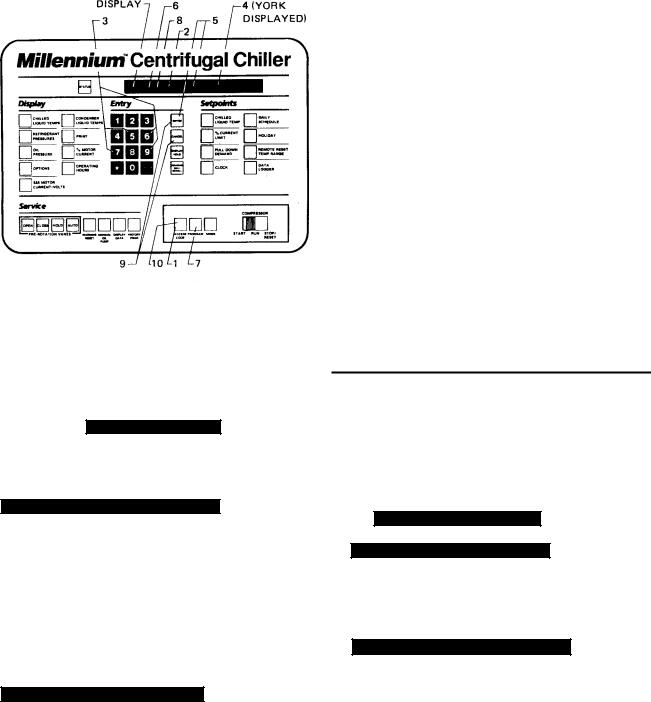
SECTION 2
MICROCOMPUTER CONTROL CENTER
FIG. 3 – MICROCOMPUTER CONTROL CENTER AND KEYPAD
NOTE: This instruction covers operation of chillers equipped with Electro-Mechanical or Solid State Starters. If chiller is equipped with Variable Speed Drive, Form 160.00-O1 is to be used in conjunction with this manual.
WARNING
This equipment generates, uses and can radiate radio frequency energy and if not installed and used in accordance with the instructions manual, may cause interference to radio communications. Operation of this equipment in a residential area is likely to cause interference in which case the user at his own expense will be required to take whatever action may be required to correct the interference.
Additionally, any electronic equipment can generate EMI (electromagnetic interference) which, depending upon the installation and magnitude, may affect other electronic equipment. The amount of EMI generated is determined by the source inductance, load inductance, and circuit impedances. Responsibility for assuring the satisfactory operation of other equipment included in the same power source as the YORK equipment rests solely with the user. YORK disclaims any liability resulting from any interference or for the correction thereof.
6 |
YORK INTERNATIONAL |
FORM 160.49-O2
INTRODUCTION
The YORK MicroComputer Control Center is a microprocessor based control system for R-22 or R134a centrifugal chillers. It controls the leaving chilled water temperature via pre-rotation vane control and has the ability to limit motor current via control of the pre-rotation vanes. Further, it is compatible with YORK Solid State Starter (optional), Variable Speed Drive (optional), and electromechanical starter applications.
A keypad mounted on the front of the Control Center (see Fig. 3) allows the operator to display system operating parameters on a 40 character alphanumeric display that is part of the keypad. These readings are displayed via “Display” keypad as follows: (In the English mode; temperatures in °F, pressures in (PSIG) (in the metric mode, temperatures in °C, Pressures in KPa).
If unit is equipped with EPROM version C.02F(T).12 or later, the Control Center can be equipped with an optional Chinese language display, either as a field retrofit or factory supplied option on new units. This display mounts on the control center door, directly above the standard display. Both the standard and Chinese display will be present, providing display messages simultaneously in both English and Chinese language.
The Control Center must be configured for Chinese display by a qualified service technician. Instructions are contained in YORK service manual, Form 160.49-M3.
•CHILLED LIQUID TEMPERATURES – LEAVING AND RETURN
•REFRIGERANT PRESSURES – EVAPORATOR AND CONDENSER
•DIFFERENTIAL OIL PRESSURE
•CONDENSER LIQUID TEMPERATURES – OPTIONAL FIELD INSTALLED – LEAVING AND RETURN
•OPTIONS
•PRINT *
•HISTORY PRINT *
•MOTOR CURRENT IN % OF FULL LOAD AMPS
•SATURATION TEMPERATURES – EVAPORATOR AND CONDENSER
•DISCHARGE TEMPERATURE
•OIL TEMPERATURE
•HIGH & LOW OIL PRESSURE TRANSDUCER PRESSURE
•SOLID STATE STARTER MOTOR CURRENT / VOLTS (When Supplied)
•CONDENSER REFRIGERANT LEVEL
*These keys provide a print-out when the customer connects a compatible printer to the Micro Board RS-232 serial port. (See Form 160.49-N7.)
The system setpoints (see Fig. 3) are operator entered on the front control center Setpoints keypad. These setpoints can also be displayed on the 40 character alphanumeric display. The system setpoints are:
•CHILLED LIQUID TEMPERATURE (LCWT)
•% CURRENT LIMIT
•PULLDOWN DEMAND LIMIT
•CLOCK (TIME-OF-DAY)
•DAILY SCHEDULE (7 DAY TIME-CLOCK PROGRAMMING)
•HOLIDAY
•REMOTE RESET TEMPERATURE RANGE
•DATA LOGGER
•CONDENSER REFRIGERANT LEVEL
The cause of all system shutdowns (safety or cycling) is preserved (until the system is reset or restarts) in the microcomputer’s memory for subsequent viewing on the keypad display. The operator is continually advised of system operating conditions by various background and warning messages. The keypad contains special service keys for use by the service technician when performing system troubleshooting.
The MicroComputer Control Center is designed to be compatible with most Energy Management Systems (EMS) in use today. The standard design allows for the following EMS interface:
1.Remote Start
2.Remote Stop
3.Remote LCWT Setpoint (Pulse Width Modulated signal)
4.Remote Current Limit Setpoint (Pulse Width Modulated signal)
5.A “Remote Mode Ready to Start” Status Contacts
6.Safety Shutdown Status Contacts
7.Cycling Shutdown Status Contacts
As an enhancement to the standard EMS features, an optional card file with plug-in printed circuit boards is available. These optional cards will accept a remote LCWT 0 to 10°F or 0 to 20°F setpoint offset and/or remote current limit setpoint interface from three user input choices.
1.4-20mA
2.0-10VDC
3.Contact Closures
YORK INTERNATIONAL |
7 |
CONTROL CENTER
The Control Center front panel layout consists of five key groups, one switch and a 1 line by 40 character alphanumeric vacuum fluorescent display: (see Fig. 3.)
CHARACTERISTIC DISPLAY – The alphanumeric vacuum fluorescent display is located to the right of the STATUS key. All messages, parameters, set points, and data can be viewed at this location.The main communications between the operator or service technician and the MicroComputer Control Center occurs on this display.
DISPLAY – Provide a direct readout of each monitored parameter on the alphanumeric display.
ENTRY – These keys are used to enter the values for the operator programmed setpoints.These keys are used in conjunction with the Setpoint keys while in PROGRAM mode.
SETPOINTS – These keys are used as follows:
1.To view each setpoint, in any mode, or
2.To select the individual setpoints that are programmed by the operator in PROGRAM mode only.
Pressing the appropriate key enables the operator to program that setpoint pressing the Entry keys.
SERVICE – Included in this group of keys are those functions that are only relevant to servicing the chiller.
Typically, these keys would not be used for daily chiller operation.
ACCESS CODE – Permits operator to access the program.
PROGRAM – Permits operator to program the Control Center.
MODE – Permits operator to check what mode the Control Center is presently in (LOCAL, REMOTE or SERVICE).
1.Service – allows manual PRV control with visual display readout of PRV operation.
2.Local – allows manual compressor start from the COMPRESSOR switch on the Control Center front.
3.Program – allows operator programming of system setpoints.
4.Remote – allows remote start, remote stop of compressor and remote reset of LCWT and % current limit.
COMPRESSOR-START, RUN, STOP/RESET SWITCH – This 3-position rocker switch is used to start (except in REMOTE mode), stop/run/reset the system.
OPERATION
DISPLAYING SYSTEM PARAMETERS
The Display keys are used to display selected monitored parameters as follows: (Refer to Fig. 3.)
•Press and release the appropriate Display key – the message will be displayed for 2 seconds.
–or –
•Press and hold the appropriate Display key – the message will be displayed and updated every 0.5 seconds until the Display key is released.
–or –
•Press and release appropriate Display key, then press and release the DISPLAY HOLD key – the message
will be displayed and updated every 2 seconds until the DISPLAY HOLD key is again pressed and released, or 10 minutes have elapsed, whichever comes first.
NOTE: If the display actually displays X’s, then the monitored parameter is out of normal operating range (refer to Fig. 4). If the “English/Metric” jumper is installed on the Micro Board, all temperatures are displayed in degrees Fahrenheit (°F) and all pressures are displayed in pounds per sq. inch gauge (PSIG) except oil pressure which is displayed in pounds per sq. inch differential (PSID). If the “English/Metric” jumper is not installed, all temperatures are displayed in degrees Centigrade (°C) and all pressures are displayed in Kilo-Pascals (kPa).
8 |
YORK INTERNATIONAL |

|
|
|
DISPLAY |
|
|
|
READS |
CONDENSER PRESS. = < 6.8 PSIG, |
or > 300 PSIG |
XX.X PSIG |
|
EVAPORATOR PRESS. = < 50 PSIG, |
or > 125 PSIG |
XX.X PSIG |
|
EVAP. PRESS. (BRINE) |
= < 25 PSIG, |
or > 100 PSIG |
XX.X PSIG |
HOP TRANSDUCER |
= < 59.1 PSIG, or > 314.9 PSIG |
XX.X PSIG |
|
LOP TRANSDUCER |
= < 23.2 PSIG, or > 271.8 PSIG |
XX.X PSIG |
|
DISCHARGE TEMP. |
= < 20.3°F; |
> 226.4°F |
XXX.X°F |
OIL TEMP. |
= < 20.3°F; |
> 226.4°F |
XXX.X°F |
LEAVING CONDENSER |
= |
< 8.4°F; |
> 134.1°F |
XXX.X°F |
|
WATER TEMP. |
|||||
|
|
|
|
||
ENTERING CONDENSER |
= |
< 8.4°F; |
> 134.1°F |
XXX.X°F |
|
WATER TEMP. |
|||||
|
|
|
|
||
|
|
|
|
||
LEAVING EVAPORATOR |
= < 0°F |
|
XX.X°F |
||
WATER TEMP. |
= > 81.1°F |
|
XX.X°F |
||
|
|
|
|
||
ENTERING EVAPORATOR |
= < .1°F |
|
XX.X°F |
||
WATER TEMP. |
= > 93°F |
|
XX.X°F |
||
|
|
|
|
|
|
FIG. 4 – SYSTEM PARAMETERS – OUT OF RANGE READINGS
To Display CHILLED LIQUID TEMPERATURES:
Press CHILLED LIQUID TEMPS display key as described on page 7 to produce the following alphanumeric display message:
CHILLED LEAVING = XXX.X°F, RETURN = XXX.X°F
To Display REFRIGERANT PRESSURE:
Use REFRIGERANT PRESSURE display key as described on page 7 to produce the following alphanumeric display message:
EVAP = XXX.X PSIG; COND = XXX.X PSIG
To Display OIL PRESSURE:
Use OIL PRESSURE display key as described on page 7 to produce the following alphanumeric display message:
OIL PRESSURE = XXXX.X PSID
The differential pressure displayed is the pressure difference between the high side oil pressure transducer (output of oil filter) and the low side oil pressure transducer (compressor housing). Displayed value includes offset pressure derived from auto-zeroing during “START SEQUENCE INITIATED”. If either transducer is out-of-range, XX.X is displayed. Oil pressure is calculated as follows:
FORM 160.49-O2
______ PSID = (HOP – LP) – OFFSET PRESSURE
OFFSET PRESSURE: Pressure differential between the HOP transducer and LOP transducer outputs during a 3 second period beginning 10 seconds after the start of “START SEQUENCE INITIATED”. During this time, the transducers will be sensing the same pressure and their outputs should indicate the same pressure. However, due to accuracy tolerances in transducer design, differences can exist. Therefore, to compensate for differences between transducers and assure differential pressure sensing accuracy, the OFFSET PRESSURE is subtracted algebraically from the differential pressure. The offset pressure calculation will not be performed if either transducer is out-of-range. The offset value will be taken as 0 PSI in this instance.
To Display OPTIONS:
This key is not used.
NO OPTIONS INSTALLED
is displayed when this key is pressed.
To Display SSS MOTOR CURRENT / VOLTS:
(Solid State Starter Applications Only)
If chiller is equipped with aYORK Solid State Starter, use SSS MOTOR CURRENT / VOLTS key to display 3-phase compressor motor current and 3-phase Solid State Starter input line voltage.
Continuously pressing this key will display the motor current and line voltage alternately. When used with the DISPLAY HOLD key, motor current and line voltage will alternately be displayed each time this key is pressed. The messages are as follows:
A AMPS = XXXX; B AMPS = XXXX; C AMPS = XXXX
V A-B = XXXX; V B-C = XXXX; V C-A = XXXX
If chiller is not equipped with a Solid State Starter, this key produces the following message:
SOLID STATE STARTER NOT INSTALLED
In PROGRAM mode, this key is used to display the applicable line voltage range (200-208VAC, 220240VAC, 380VAC, 400VAC, 415VAC, 440-480VAC, 500-600VAC, Supply Voltage Range Disabled).The correct line voltage range is programmed at the YORK factory and is checked by the service technician at start-up. For security reasons, a special access code is required to program the line voltage range. The line voltage range is used to determine a low line voltage threshold for cycling shutdown. Refer to “System Setpoints” for Trip/Reset values.
YORK INTERNATIONAL |
9 |

To Display CONDENSER LIQUID TEMPERATURES
(Field Installed Option Package):
Use CONDENSER LIQUID TEMPS display key as described above to produce the following alphanumeric display message:
COND LEAVING = XXX.X°F; RETURN = XXX.X°F
NOTE: If the condenser liquid thermistors are not connected, or both thermistors are “out of range”, the display will blank when this key is pressed.
To Initiate a PRINT to Printer:
Press the PRINT key to initiate a printout to an optional printer. When the key is pressed,
PRINT ENABLE |
is displayed. |
Refer to “MicroComputer Control Center – System Status Printers” instruction, Form 160.49-N7 for details of the optional printers.
To Display MOTOR CURRENT:
Press the % MOTOR CURRENT display key as described above to display motor current as a percent of Full Load Amps (FLA). The message is as follows:
MOTOR CURRENT = XXX% FLA
NOTE: • Liquid-Cooled Solid State Starter Applications
– the % Motor Current displayed is the highest of three line currents divided by the programmed chiller FLA value x 100%.
• Electro-Mechanical Starter Applications – the % Motor Current displayed is the highest of the three line currents.
To Display OPERATING HOURS and STARTS
COUNTER:
Use the OPERATING HOURS key as described on page 8, to produce the following message:
OPER. HOURS = XXXXX; START COUNTER = XXXXX
NOTE: The operating hours and starts counter can be reset to zero. Refer to “Programming the Micro-
Computer Control Center”, page 14. However, the purpose of the OPERATING HOURS key is to display the total accumulated chiller run time. Therefore, the operating hours should not be arbitrarily reset.
SYSTEM SETPOINTS
The system setpoints may be programmed by the system operator. The Setpoints keys are located on the Control Center keypad (see Fig. 3).To program, see “Programming System Setpoints”, page 14. The following is a description of these setpoints (with the English/ Metric jumper installed on the Micro Board):
CHILLED LIQUID TEMP – This key displays the leaving chilled water temperature (LCWT) setpoint in degrees Fahrenheit. If not programmed, the default value is 45°F. See “Programming System Setpoints”, page 15).
NOTE: If an Energy Management System is interfaced to the Control Center for the purpose of remote LCWT setpoint reset, then the operator-pro- grammed chilled liquid temperature will be the base or lowest setpoint available to the Energy Management System (EMS). This chilled liquid temperature value must also be entered into the EMS. Further, any subsequent change to this value must also be entered into the EMS.
% CURRENT LIMIT – This key displays the maximum value of motor current permitted by its programmed setting. The value is in terms of percent of Full Load Amps (FLA). If not programmed, the default value is 100%. (See “Programming System Setpoints”, page 15.)
If chiller is equipped with a YORK Solid State Starter, the system FLA is also displayed. This value is programmed by the factory and should never be changed. The Micro Board uses this value to calculate and display the % motor current parameter that is displayed when the % MOTOR CURRENT display key is pressed. Also, proper current limit control depends on the correctly programmed FLA value. For security reasons, a special access code is required to program the FLA value. It should only be changed by a service technician.
PULL DOWN DEMAND – This function is used to provide energy savings following the chiller start-up. This key displays a programmable motor current limit and a programmable period of time. Operation is as follows: Whenever the system starts, the Pull Down Demand Limit is maintained for the programmed time, then the current limit control returns to % current limit setpoint. The maximum permitted motor current is in terms of % FLA. The duration of time that the current is limited is in
10 |
YORK INTERNATIONAL |
terms of minutes (to a maximum of 255). If not programmed, the default value is 100% FLA for 00 minutes. (See “Programming Systems Setpoints”, page 16.) Thus, no pull down demand limit is imposed following system start, and the % current limit setpoint is used.
CLOCK – This key displays the day of the week, time of day and calendar date. If not programmed, the default value is SUNDAY 12:00 AM 1/1/92 .
(See “Programming System Setpoints”, page 16.)
DAILY SCHEDULE – This key displays the programmed daily start and stop times, from Sunday thru Saturday plus Holiday. If desired, the Control Center can be programmed to automatically start and stop the chiller as desired. This schedule will repeat on a 7-day calendar basis. If the Daily Schedule is not programmed, the default value is 00:00 AM start and stop times for all days of the week and the holiday. (Note that the system will not automatically start and stop on a daily basis with these default values because 00:00 is an “Impossible” time for the Micro Board. See “Programming System Setpoints”, page 17.) Finally, one or more days in the week can be designated as a holiday (see description under HOLIDAY setpoint) and the Control Center can be programmed (usually Daily Schedule setpoint) to automatically start and stop the chiller on those days so designated. The operator can override the time clock at any time using the COMPRESSOR switch.
Note that if only a start time is entered for a particular day, the compressor will not automatically stop until a scheduled stop time is encountered on a subsequent day.
HOLIDAY – This key indicates which days in the upcoming week are holidays. On those designated days, the chiller will automatically start and stop via the holiday start and stop times programmed in the DAILY SCHEDULE setpoint. It will do this one time only and the following week will revert to the normal daily schedule for that day.
REMOTE / RESET TEMP RANGE – This key displays the maximum offset of remote LCWT setpoint reset.This offset is either 10° or 20°F as programmed. When in the REMOTE mode, this value is added to the operator programmed CHILLED LIQUIDTEMP setpoint and the sum equals the temperature range in which the LCWT can be reset. For example, if the operator programmed CHILLED LIQUID TEMP setpoint is programmed with a value of 10°F, then the CHILLED LIQUIDTEMP setpoint can be remotely reset over a range of 46°F to 56°F (46 + 10 = 56). If not programmed, the default value for this parameter is 20°F.
FORM 160.49-O2
For additional information on remote LCWT reset, refer to Form 160.49-PW13.
NOTE: If an Energy Management System is interfaced to the Control Center for the purpose of remote LCWT setpoint reset, then the operator programmed REMOTE RESET TEMP RANGE value determines the maximum value of temperature reset controlled by the Energy Management System.
DATE LOGGER – This key is used when an optional printer is connected to the MicroComputer Control Center. Refer to Form 160.49-N7 for operation instructions.
SSS MOTOR CURRENT/VOLTS – This key is used on Solid State Starter applications only. Although this is a display key, it is used to program the applicable AC power line voltage range (380VAC, 400VAC, 415VAC, 440-480VAC, 550-600VAC). The MicroComputer Control Center uses this entry to determine the under-volt- age and overvoltage shutdown threshold. For each line voltage category, there is an undervoltage and overvoltage shutdown threshold. If the AC power line voltage exceeds these thresholds for 20 continuous seconds, the chiller shuts down and displays
MON 10:00 AM LOW LINE VOLTAGE
– or –
MON 10:00 AM HIGH LINE VOLTAGE
This overvoltage and undervoltage protection can be disabled. Refer to chart below:
LOW / HIGH LINE VOLTAGE TRIP / RESET VALUES
COMPRESSOR |
LOW LINE VOLTAGE |
HIGH LINE VOLTAGE |
|||
OPERATING POINT |
OPERATING POINT |
||||
MOTOR |
|||||
|
|
|
|
||
SUPPLYVOLTAGE |
CUTOUT-(V) |
CUTIN-(V) |
CUTOUT-(V) |
CUTIN-(V) |
|
RANGE – (V) |
|||||
(ON FALL) |
(ON RISE) |
(ON RISE) |
(ON FALL) |
||
|
|||||
|
|
|
|
|
|
380 |
305 |
331 |
415 |
414 |
|
400 |
320 |
349 |
436 |
435 |
|
415 |
335 |
362 |
454 |
453 |
|
440-480 |
370 |
400 |
524 |
523 |
|
|
|
|
|
|
|
550-600 |
460 |
502 |
655 |
654 |
|
Supply Voltage |
NONE |
0 |
NONE |
0 |
|
Range Disabled |
|||||
|
|
|
|
||
|
|
|
|
|
|
For security reasons, a special access code is required to program the supply voltage range.The supply voltage range is programmed at the factory and should only be changed by a service technician.
YORK INTERNATIONAL |
11 |

DISPLAYING SYSTEM SETPOINTS
The currently programmed Setpoint values can be viewed at any time (see page 22) in SERVICE, LOCAL or REMOTE operating mode as follows:
•Press and release the appropriate Setpoint key – the message will be displayed for 2 seconds.
–or –
•Press and hold the appropriate Setpoint key – the message will be displayed as long as the key is pressed.
–or –
•Press and release the appropriate Setpoint key, then press and release the DISPLAY HOLD key.The message will be displayed until the DISPLAY HOLD key is again pressed and released, or 10 minutes have elapsed, whichever comes first.
To Display CHILLED LIQUID TEMP Setpoint:
Use CHILLED LIQUID TEMP setpoint key as described on page 10 to produce the following message:
LEAVING SETPOINT = XX.X °F
NOTE: The value displayed is the actual LCWT setpoint. For example, the value displayed in LOCAL or PROGRAM modes is that which is operator programmed. The value displayed in the REMOTE mode is that base setpoint with added temperature reset by an Energy Management System, via remote LCWT setpoint (PWM signal) if a remote reset signal was received within 30 minutes.
To Display % CURRENT LIMIT Setpoint:
Use % CURRENT LIMIT setpoint key as described above to produce the following message:
CURRENT LIMIT = XXX % FLA
NOTE: The value displayed is the actual % current limit setpoint. For example, the value displayed in LOCAL or PROGRAM mode is that which is operator programmed. The value displayed in the REMOTE mode is that which has been programmed by the Energy Management System via the remote current limit setpoint input.
If chiller is equipped with a YORK Solid State Starter, the message is:
CURRENT LIMIT = XXX % FLA; *MTR CUR = 000 FLA
NOTE: On Solid State Starter applications, this value is programmed at the YORK factory. A special access code is required.
To Display PULL DOWN DEMAND Setpoint:
Use PULL DOWN DEMAND setpoint key as described on page 10 to produce the following message:
SETPOINT = XXX MIN @ XX % FLA XXX MIN LEFT
To Display CLOCK Setpoint (Time of Day):
Use CLOCK setpoint key as described above to produce the following message:
TODAY IS DAY XX:XX AM/PM 1/1/92
To Display DAILY SCHEDULE Setpoints:
•Press and hold the DAILY SCHEDULE setpoint key.
The chiller start and stop times for each day of the week are sequentially displayed, beginning with Sunday and ending with Holiday. The display will continuously scroll until the DAILY SCHEDULE key is released.
–or –
•Press and release the DAILY SCHEDULE setpoint key. Then press and release the DISPLAY HOLD key.The chiller start and stop times for each day of the week are sequentially displayed beginning with Sunday and ending with Holiday.The display will continuously scroll until the DISPLAY HOLD key is again pressed and released, or 10 minutes have elapsed, whichever comes first.
The display message for DAILY SCHEDULE will scroll in the following sequence:
SUN START = 08:30 AM |
STOP = 06:00 PM |
|
|
MON START = 05:00 AM |
STOP = 07:00 PM |
|
|
12 |
YORK INTERNATIONAL |

TUE START = 05:00 AM |
STOP = 07:00 PM |
|
|
WED START = 05:00 AM |
STOP = 07:00 PM |
|
|
THU START = 05:00 AM |
STOP = 07:00 PM |
|
|
FRI START = 05:00 AM |
STOP = 07:00 PM |
|
|
SAT START = 05:00 AM |
STOP = 01:00 PM |
|
|
HOL START = 00:00 AM |
STOP = 00:00 PM |
|
|
To Display HOLIDAY Setpoints:
Use HOLIDAY setpoint key as described in the beginning of this section to produce the following message:
S_ M_ T_ W_ T_ F_ S_ HOLIDAY NOTED BY *
NOTE: On the days that are designated by an *, the chiller will automatically start and stop per the holiday schedule established in DAILY SCHEDULE setpoints.
To Display REMOTE RESET TEMP RANGE Setpoint:
Use REMOTE RESET TEMP RANGE setpoint key as described above to produce the following message:
REMOTE RESET TEMP RANGE = 10°F
– or –
REMOTE RESET TEMP RANGE = 20°F
To Display DATA LOGGER setpoints:
Refer toYORK, Form 160.49-N7 for operation of this key.
FORM 160.49-O2
To Display UNDERVOLTAGE setpoints:
(Solid State Starter Applications Only)
Press SSS MOTOR CURRENT/VOLTS key in PROGRAM mode to display the selected voltage range. One of the following messages will be displayed.
SUPPLY VOLTAGE RANGE 380
– or –
SUPPLY VOLTAGE RANGE 400
– or –
SUPPLY VOLTAGE RANGE 415
– or –
SUPPLY VOLTAGE RANGE 440-480
– or –
SUPPLY VOLTAGE RANGE 550-600
– or –
SUPPLY VOLTAGE RANGE DISABLED
A special access code is required to program the Supply Voltage Range. The Supply Voltage Range is programmed at the factory and checked at system start-up. (Note to service technician: Refer to programming instructions in Service Instruction, Form 160.49-M3.)
YORK INTERNATIONAL |
13 |
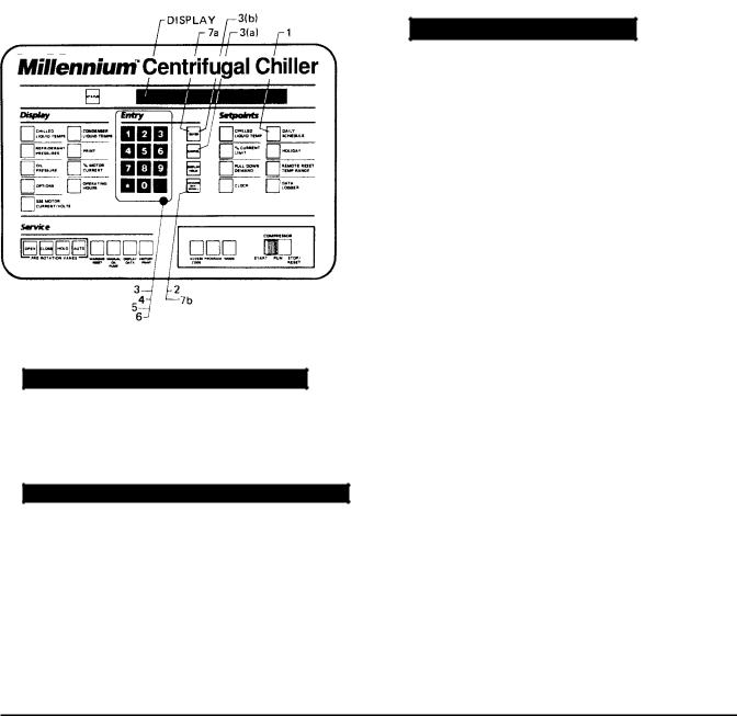
PROGRAMMING
THE MICROCOMPUTER CONTROL CENTER
PROGRAMMING SYSTEM SETPOINTS
The system setpoints can be entered at any time . . . . .
even when the system is running. Proceed as follows to enter system setpoints. (Refer to Fig. 5.)
1. Press ACCESS CODE key.
2. ENTER VALID ACCESS CODE _ _ _ _ is displayed.
3.Using ENTRY keys, enter 9 6 7 5.
4.As each digit is entered, the characters Y O R K are displayed.
NOTE: If digits other than 9 6 7 5 are entered, Y O R K is still displayed.
NOTE: For ease in remembering the code, note that the letters Y O R K correspond to the digits 9 6 7 5 on a telephone dial.
5. Press ENTER key.
NOTE: If digits other than 9 6 7 5 were entered in step No. 4, INVALID ACCESS CODE is displayed when the ENTER key is pressed. If this occurs, enter the correct access code (9675) and proceed.
6. ACCESS TO PROGRAM KEY AUTHORIZED is displayed.
NOTE: Unless terminated by pressing the ACCESS CODE key again, the operator will have access to the PROGRAM key for 10 minutes. When 10 minutes have elapsed, access to PROGRAM key will be automatically disabled and the operator must return to step No. 1 to gain access.
7. Press PROGRAM key.
8. PROGRAM MODE, SELECT SETPOINT is displayed.
LD00954
FIG. 5 – KEYPAD – PROGRAMMING SYSTEM SETPOINTS
9.Enter setpoints as detailed below. If you make a mistake when entering a value, press CANCEL key and then ENTER key.The display will revert to the default values and the cursor will return to the first changeable digit.You can then proceed to enter the correct values. If the entered value exceeds acceptable limits, OUT OF RANGE – TRY AGAIN!
message will be displayed for 2 seconds, then the
PROGRAM MODE, SELECT SETPOINT message will reappear.
10.When all the desired setpoints have been entered, press the ACCESS CODE key to exit PROGRAM mode and terminate access to PROGRAM mode.
ACCESS TO PROGRAM MODE DISABLED is displayed. The Control Center will automatically return to LOCAL, REMOTE or SERVICE mode . . . . whichever was last selected.
14 |
YORK INTERNATIONAL |

FORM 160.49-O2
To enter CHILLED LIQUID TEMP Setpoint: (Refer to
Fig. 6.)
1.Press and release CHILLED LIQUID TEMP setpoint key. The following program prompt message will be displayed:
LEAVING SETPOINT = XX.X °F (BASE)
(BASE) refers to the base or lowest setpoint available to an Energy Management System. If any Energy Management System is applied, this value must be entered into the Energy Management System. Refer to previous explanation or REMOTE/RESET TEMP RANGE, page 11.
2. |
Use ENTRY keys to enter desired value. |
LD00955 |
||
|
|
|
|
|
3. |
Press and release ENTER key. |
|
||
|
|
|
|
FIG. 6 – KEYPAD – PROGRAMMING “LEAVING |
|
|
PROGRAM MODE, SELECT SETPOINT |
|
|
|
|
|
CHILLED WATER TEMP” SETPOINT |
|
|
|
message is displayed. |
||
|
|
|
||
|
|
|
|
|
To Enter % CURRENT LIMIT Setpoint: (Electro-Mechanical Starter, refer to Fig. 7)
1.Press and release % CURRENT LIMIT setpoint key. The following program prompt message is displayed:
CURRENT LIMIT = XXX% FLA
2.Use ENTRY keys to enter desired value.
3.Press and release ENTER key.
PROGRAM MODE, SELECT SETPOINT
message is displayed.
(Solid State Starter, refer to Fig. 7)
1.Press and release % CURRENT LIMIT setpoint key. The following program prompt message is displayed:
CURRENT LIMIT = XXX% FLA; MTR CUR = _ _ _ FLA
2.Use ENTRY keys to enter desired value.
NOTE: Motor Current FLA value is entered by YORK factory and checked at system start-up. It cannot be changed without special access code. (Note to service technician: refer to “Programming Instructions” in Service instruction, Form 160.49-M3.
3. Press and release ENTER key.
PROGRAM MODE, SELECT SETPOINT
message is displayed.
LD00956
FIG. 7 – KEYPAD – PROGRAMMING “% CURRENT LIMIT” SETPOINT
YORK INTERNATIONAL |
15 |

To Enter PULL DOWN DEMAND Setpoint: (Refer to Fig. 8.)
1.Press and release PULL DOWN DEMAND setpoint key. The following program prompt message is displayed:
SETPOINT = XXX MIN @ XXX % FLA, XXX MIN LEFT
2.Use Entry keys to enter desired values. For explanation, see PULL DOWN DEMAND, page 12. Note that “XX min left” is not an operator entered value.
3.Press and release ENTER key.
PROGRAM MODE, SELECT SETPOINT
message is displayed.
FIG. 8 – KEYPAD – PROGRAMMING “PULL DOWN
DEMAND” SETPOINT
To Enter CLOCK Setpoint: (Refer to Fig. 9.)
1.Assure Micro Board Program jumper J57 is in “CLKON” position.
2.Press and release CLOCK setpoint key. The following program prompt message is displayed:
TODAY IS MON 10:30 PM 1/1/92
3.Press ADVANCE DAY / SCROLL key until the program per day of week appears on the display.
4.Use Entry keys to enter proper time of day.
5.Press AM/PM key to change the AM to PM or vice versa.
6.Use Entry keys to enter proper calendar date,
(MONTH/DAY/YR). If month and day are single digit |
LD00958 |
|||
|
||||
entries, precede the entry with “0”. For example, |
|
|||
02/04/88. |
|
|
||
7. Press and release ENTER key. |
FIG. 9 – KEYPAD – PROGRAMMING “CLOCK” |
|||
SETPOINT |
||||
|
|
|
||
|
PROGRAM MODE, SELECT SETPOINT |
|
|
|
|
message is displayed. |
|
||
|
|
|
|
|
16 |
YORK INTERNATIONAL |
To Enter DAILY SCHEDULE Setpoint: (Refer to Fig. 10.)
1.Press and release DAILY SCHEDULE setpoint key. The following prompt message is displayed:
SUN START = XX:XX AM, STOP = XX:XX AM
2.If the displayed start and stop time is not the desired schedule, enter the desired start and stop times as follows:
a.If you do not want the chiller to automatically start and stop on this day, press CANCEL key.
b.Use the Entry keys to enter desired hours and minutes start time.
c.If necessary, press the AM/PM key to change “AM” to “PM” or vice versa.
d.Use the Entry keys to enter desired hours and minutes stop time.
e.If necessary, press the AM/PM key to change “AM” to “PM” or vice versa.
3.Press and release ADVANCE DAY/SCROLL key.The following prompt message is displayed:
MON START = XX:XX AM, STOP = XX:XX AM
4.Enter the desired start and stop time per Step 2.
5.Press and release ADVANCE DAY/SCROLL key.The following prompt message is displayed:
REPEAT MON SCHEDULE MON-FRI? YES = 1; NO = 0
a.If you press the 1 Entry key, Monday’s start and stop time will be automatically entered for Tuesday through Friday.
–or –
b.If you press the 0 Entry key, Tuesday through Friday can be programmed with different start and stop times.
FORM 160.49-O2
6.Use the ADVANCE DAY / SCROLL key with procedure in Step 2. To enter start and stop times for remainder of the week plus a holiday schedule if required.
7.Press the ENTER key.
PROGRAM MODE, SELECT SETPOINT is displayed.
LD00959
FIG. 10 – KEYPAD – PROGRAMMING “DAILY
SCHEDULE” SETPOINT
YORK INTERNATIONAL |
17 |
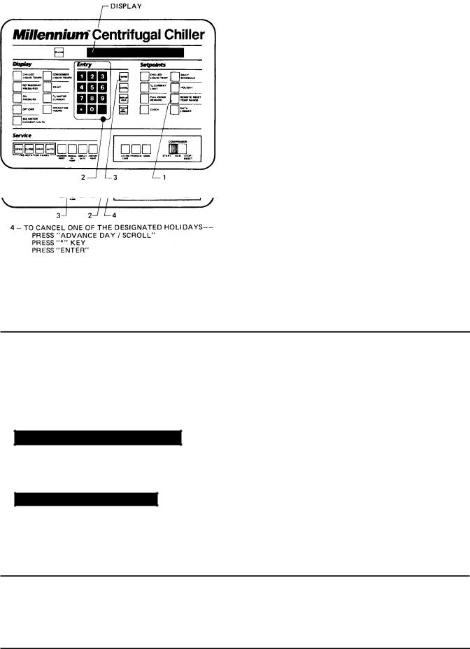
To Enter HOLIDAY Setpoint: (Refer to Fig. 11.)
1.Press and release HOLIDAY setpoint key. The following program prompt message is displayed:
S_ M_ T_ W_ T_ F_ S_ HOLIDAY NOTED BY r
2.Press and release ADVANCE DAY/SCROLL key to move cursor to the day that you wish to designate as a holiday.
3.Press and release r entry key. An r will appear next to the selected day.
4.After you have placed an r next to each of the days that you wish to designate a holiday, press ENTER key PROGRAM MODE, SELECT SETPOINT
message is displayed.
To cancel all of the designated holidays: perform Step 1, press CANCEL key, and then press ENTER key.
PROGRAM MODE, SELECT SETPOINT
message is displayed. |
|
To cancel one of the designated holidays: perform |
|
Step 1, press ADVANCE DAY / SCROLL key until |
FIG. 11 – KEYPAD – PROGRAMMING “HOLIDAY” |
the cursor appears to the right of the desired day, |
|
press the r key, then press the ENTER key. |
SETPOINT |
To Enter REMOTE/ RESET TEMP RANGE Setpoint: (Refer to Fig. 12.)
1.Press and release REMOTE/RESET TEMP RANGE setpoint key.The following program prompt message is displayed:
REMOTE TEMP SETPOINT RANGE = XX °F
2.Use Entry keys desired value (10 or 20).
3.Press and release ENTER key.
PROGRAM MODE, SELECT SETPOINT
message is displayed.
FIG. 12 – KEYPAD – PROGRAMMING “REMOTE
RESET” TEMP RANGE
To Enter DATA LOGGER Setpoint:
Refer to Form 160.49-N7 for operation of this key.
18 |
YORK INTERNATIONAL |
Loading...