


 Loading...
MILLENNIUM ®
AIR-COOLED LIQUID CHILLERS
HERMETIC SCROLL
INSTALLATION, OPERATION, MAINT. Supersedes: 150.62-NM1 (899) |
Form 150.62-NM1 (700) |
YCAL0014SC - YCAL0080SC
29224(R)A
200-3-60
230-3-60
380-3-60
460-3-60
575-3-60 MODELS ONLY
Standard, Glycol & Metric Models, Combined

IMPORTANT!
READ BEFORE PROCEEDING!
GENERAL SAFETY GUIDELINES
This equipment is a relatively complicated apparatus. During installation, operation, maintenance or service, individuals may be exposed to certain components or conditions including, but not limited to: refrigerants, oils, materials under pressure, rotating components, and both high and low voltage. Each of these items has the potential, if mis-used or handled improperly, to cause bodily injury or death. It is the obligation and responsibility of operating/service personnel to identify and recognize these inherent hazards, protect themselves, and proceed safely in completing their tasks. Failure to comply with any of these requirements could result in serious damage to the equipment and the property in which it is situated, as well as severe personal injury or death to themselves and people at the site.
This document is intended for use by owner-authorized operating/service personnel. It is expected that this individual possesses independent training that will enable them to perform their assigned tasks properly and safely. It is essential that, prior to performing any task on this equipment, this individual shall have read and understood this document and any referenced materials. This individual shall also be familiar with and comply with all applicable governmental standards and regulations pertaining to the task in question.
SAFETY SYMBOLS
The following symbols are used in this document to alert the reader to areas of potential hazard:
DANGER indicates an imminently hazardous situation which, if not avoided, will result in death or serious injury.
WARNING indicates a potentially hazardous situation which, if not avoided, could result in death or serious injury.
2 |
YORK INTERNATIONAL |

FORM 150.62-NM1
CAUTION identifies a hazard which could lead to damage to the machine, damage to other equipment and/or environmental pollution. Usually an instruction will be given, together with a brief explanation.
NOTE is used to highlight additional information which may be helpful to you.
CHANGEABILITY OF THIS DOCUMENT
In complying with YORK’s policy for continuous product improvement, the information contained in this document is subject to change without notice. While YORK makes no commitment to update or provide current information automatically to the manual owner, that information, if applicable, can be obtained by contacting the nearest YORK Engineered Systems Service office.
It is the responsibility of operating/service personnel to verify the applicability of these documents to the equipment in question. If there is any question in the mind of operating/service personnel as to the applicability of these documents, then prior to working on the equipment, they should verify with the owner whether the equipment has been modified and if current literature is available.
YORK INTERNATIONAL |
3 |
TABLE OF CONTENTS AND TABLES
|
|
|
|
|
PAGE |
PRODUCT IDENTIFICATION NUMBER .......................................................... |
7 |
||||
REFRIGERANT FLOW DIAGRAM ................................................................... |
9 |
||||
|
|
|
|
|
|
SECTION |
1 |
|
INSTALLATION .......................................................................... |
10 |
|
ELECTRICAL DATA ....................................................................................... |
20 |
||||
OPERATIONAL LIMITATIONS ....................................................................... |
30 |
||||
PHYSICAL DATA ............................................................................................ |
34 |
||||
DIMENSIONS & CLEARANCES .................................................................... |
38 |
||||
PRE-STARTUP CHECKLIST ......................................................................... |
54 |
||||
INITIAL STARTUP .......................................................................................... |
55 |
||||
UNIT OPERATING SEQUENCE .................................................................... |
57 |
||||
|
|
|
|
|
|
SECTION |
2 |
|
UNIT CONTROLS ...................................................................... |
58 |
|
STATUS KEY.................................................................................................. |
60 |
||||
DISPLAY/PRINT KEYS .................................................................................. |
66 |
||||
ENTRY KEYS ................................................................................................. |
73 |
||||
SETPOINTS KEY ........................................................................................... |
74 |
||||
UNIT KEYS |
.................................................................................................... |
81 |
|||
UNIT OPERATION ......................................................................................... |
85 |
||||
|
|
|
|
|
|
SECTION |
3 |
|
SERVICE AND TROUBLESHOOTING ...................................... |
95 |
|
OPTIONAL PRINTER INSTALLATION ......................................................... |
104 |
||||
TROUBLESHOOTING CHARTS .................................................................. |
105 |
||||
MAINTENANCE ........................................................................................... |
108 |
||||
ISN CONTROL ............................................................................................. |
109 |
||||
|
|
|
|
|
|
SECTION |
4 |
|
WIRING DIAGRAMS ............................................................... |
112 |
|
|
|
|
|
|
|
SECTION |
5 |
|
APPENDIX 1 – ISOLATORS .................................................... |
128 |
|
YORK APPLIED SYSTEMS FIELD OFFICE LISTING ................................. |
134 |
||||
TABLES |
|
|
|
|
|
1 |
MICROPANEL POWER SUPPLY ............................................................ |
20 |
|||
2 |
STANDARD SINGLE POINT POWER ..................................................... |
21 |
|||
3 |
STANDARD DUAL POINT POWER ................................................ |
22 – 23 |
|||
4 |
OPTIONAL SINGLE POINT POWER .............................................. |
24 – 25 |
|||
5 |
OPTIONAL SINGLE POINT POWER .............................................. |
26 – 27 |
|||
6 |
OPTIONAL SINGLE POINT POWER .............................................. |
28 – 29 |
|||
7 |
TEMPERATURES AND FLOWS (ENGLISH) .......................................... |
30 |
|||
8 |
VOLTAGE LIMITATIONS (ENGLISH) ....................................................... |
30 |
|||
9 |
COOLER PRESSURE DROPS (ENGLISH) ............................................. |
31 |
|||
10 |
ETHYLENE GLYCOL CORRECTION FACTORS .................................... |
31 |
|||
11 |
TEMPERATURES AND FLOWS (METRIC) ............................................ |
32 |
|||
12 |
VOLTAGE LIMITATIONS (METRIC) ........................................................ |
32 |
|||
4 |
YORK INTERNATIONAL |
FORM 150.62-NM1
|
TABLES AND FIGURES |
|
|
|
PAGE |
TABLES |
|
|
13 |
COOLER PRESSURE DROPS (METRIC)............................................. |
33 |
14 |
ETHYLENE GLYCOL CORRECTION FACTORS .................................. |
33 |
15 |
PHYSICAL DATA (ENGLISH) ........................................................ |
34 – 35 |
16 |
PHYSICAL DATA (METRIC) .......................................................... |
36 – 37 |
17 |
WEIGHT DISTRIBUTION/CENTER OF GRAVITY (ENGLISH) ............. |
39 |
18 |
WEIGHT DISTRIBUTION/CENTER OF GRAVITY (ENGLISH) ............. |
41 |
19 |
WEIGHT DISTRIBUTION/CENTER OF GRAVITY (ENGLISH) ............. |
43 |
20 |
WEIGHT DISTRIBUTION/CENTER OF GRAVITY (ENGLISH) ............. |
45 |
21 |
WEIGHT DISTRIBUTION/CENTER OF GRAVITY (METRIC) ............... |
47 |
22 |
WEIGHT DISTRIBUTION/CENTER OF GRAVITY (METRIC) ............... |
49 |
23 |
WEIGHT DISTRIBUTION/CENTER OF GRAVITY (METRIC) ............... |
51 |
24 |
WEIGHT DISTRIBUTION/CENTER OF GRAVITY (METRIC) ............... |
53 |
25 |
SETPOINT ENTRY LIST ....................................................................... |
54 |
26 |
STATUS KEY MESSAGES .................................................................... |
65 |
27 |
OPERATOR DATA QUICK REFERENCE .............................................. |
69 |
28 |
COOLING SETPOINTS PROGRAMMABLE LIMITS & DEFAULTS |
....... 76 |
29 |
PROGRAM KEY LIMITS & DEFAULTS ................................................. |
79 |
30 |
SETPOINTS KEY QUICK REFERENCE ............................................... |
80 |
31 |
UNIT KEYS QUICK REFERENCE ......................................................... |
84 |
32 |
LEAVING CHILLED LIQUID CONTROL – 6 COMPRESSORS ............. |
86 |
33 |
LEAVING CHILLED LIQUID CONTROL – 4 COMPRESSORS ............. |
86 |
34 |
LEAVING CHILLED LIQUID CONTROL – 3 COMPRESSORS ............. |
87 |
35 |
LEAVING CHILLED LIQUID CONTROL – 2 COMPRESSORS ............. |
87 |
36 |
COMPRESSOR STAGING FOR RETURN WATER CONTROL ............ |
89 |
37 |
RETURN CHILLED LIQUID CONTROL – 6 COMPRESSORS .............. |
89 |
38 |
RETURN CHILLED LIQUID CONTROL – 4 COMPRESSORS .............. |
89 |
39 |
CONDENSER FAN CONTROL USING OUTDOOR AMBIENT |
|
|
TEMPERATURE AND DISCHARGE ..................................................... |
90 |
40 |
CONDENSER FAN CONTROL USING DISCHARGE ONLY ................. |
90 |
41 |
LOW AMBIENT CONDENSER FAN CONTROL – AMBIENT |
|
|
TEMPERATURE AND DISCHARGE PRESSURE CONTROL ............. |
91 |
42 |
LOW AMBIENT CONDENSER FAN CONTROL – DISCHARGE |
|
|
PRESSURE CONTROL ....................................................................... |
91 |
43 |
COMPRESSOR OPERATION – LOAD LIMITING ................................. |
92 |
44 |
MICROBOARD BINARY INPUTS .......................................................... |
97 |
45 |
MICROBOARD ANALOG INPUTS ........................................................ |
97 |
46 |
MICROBOARD OUTPUTS .................................................................... |
97 |
47 |
OUTDOOR AIR SENSOR VALUES ....................................................... |
99 |
YORK INTERNATIONAL |
5 |
|
TABLES/FIGURES |
|
|
|
PAGE |
TABLES |
|
|
48 |
ENTERING & LEAVING CHILLED LIQUID TEMPERATURE |
|
|
SENSOR VALUES ............................................................................ |
100 |
49 |
KEYPAD PIN ASSIGNMENT MATRIX ................................................. |
103 |
50 |
TROUBLESHOOTING CHARTS ............................................... |
105 – 107 |
51 |
ISN RECEIVED DATA .......................................................................... |
109 |
52 |
ISN TRANSMITTED DATA .................................................................. |
109 |
53 |
ISN TRANSMITTED DATA .................................................................. |
110 |
54 |
ISN OPERATIONAL & FAULT CODES ................................................. |
111 |
FIGURES |
|
|
1 |
REFRIGERANT FLOW DIAGRAM .......................................................... |
9 |
2 |
STANDARD POWER SUPPLY WIRING ................................................ |
14 |
3 |
OPTIONAL SINGLE POINT POWER SUPPLY WIRING ....................... |
15 |
4 |
OPTIONAL SINGLE POINT POWER SUPPLY WIRING – |
|
|
N-F DISC SW OR CIRC BKR ............................................................. |
16 |
5 |
CONTROL WIRING .............................................................................. |
17 |
6 |
LEAVING WATER TEMPERATURE CONTROL – |
|
|
COMPRESSOR STAGING .................................................................. |
86 |
7 |
FIELD & FACTORY ELECTRICAL CONNECTIONS – |
|
|
REMOTE TEMPERATURE RESET BOARD ....................................... |
94 |
8 |
MICROBOARD LAYOUT ....................................................................... |
98 |
9 |
MICROBOARD RELAY CONTACTS ARCHITECTURE ....................... |
103 |
10 |
PRINTER TO MICROBOARD ELECTRICAL CONNECTIONS ........... |
104 |
11 |
ELEMENTARY DIAGRAM ................................................................... |
112 |
12 |
ELEMENTARY DIAGRAM – POWER CIRCUIT .................................. |
114 |
13 |
ELEMENTARY DIAGRAM ................................................................... |
116 |
14 |
ELEMENTARY DIAGRAM – POWER CIRCUIT .................................. |
118 |
15 |
ELEMENTARY DIAGRAM ................................................................... |
120 |
16 |
ELEMENTARY DIAGRAM – POWER CIRCUIT .................................. |
122 |
17 |
ELEMENTARY DIAGRAM ................................................................... |
124 |
18 |
ELEMENTARY DIAGRAM – POWER CIRCUIT .................................. |
126 |
19 |
TYPE CP 1 ........................................................................................... |
130 |
20 |
TYPE CP 2 ........................................................................................... |
130 |
21 |
R SPRING SEISMIC ISOLATOR ......................................................... |
131 |
22 |
TYPE CP MOUNTING ......................................................................... |
132 |
23 |
“AEQM” SPRING-FLEX MOUNTING ................................................... |
133 |
6 |
YORK INTERNATIONAL |

FORM 150.62-NM1
PRODUCT IDENTIFICATION NUMBER (PIN)
EXAMPLES:
1 |
2 |
3 |
4 |
5 |
6 |
7 |
8 |
9 |
10 |
11 |
12 |
13 14 |
15 |
|
Y C A S 1 |
3 |
8 |
5 |
E A 5 |
0 |
Y |
F A |
|||||||
Y C A L |
0 |
0 |
8 |
0 |
S C 4 |
6 |
X |
A A |
||||||
BASIC MODEL NUMBER
YCAL0080SC46xAA
1 |
|
2 |
|
3 |
|
4 |
|
5 |
6 |
7 |
8 |
|
9 |
|
10 |
|
11 |
12 |
13 |
14 |
15 |
|||||||||||||||||||||||||||||||
|
BASE PRODUCT TYPE |
NOMINAL CAPACITY |
UNIT DESIGNATOR |
REFRIGERANT |
VOLTAGE/STARTER |
DESIGN/DEVELOPMENT LEVEL |
||||||||||||||||||||||||||||||||||||||||||||||
|
|
|
|
|
|
|
|
|
|
|
|
|
|
|
|
|
|
|
|
|
|
|
|
|
|
|
|
|
|
|
|
|
|
|
|
|
|
|
|
|
|
|
|
|
|
|
|
|
|
|
|
|
|
Y |
|
|
|
|
|
|
|
|
|
: YORK |
|
0 |
|
|
# |
|
# |
|
# |
|
S |
: Standard Unit |
|
C |
: R-22 |
|
|
1 |
|
7 |
|
|
: 200 / 3/ 60 |
|
A |
|
|
|
|
: Design Series A |
|||||||||||
|
|
|
|
C |
|
|
|
|
|
: Chiller |
1 |
# |
# |
# |
|
|
|
|
|
|
|
|
|
2 |
8 |
|
|
: 230 / 3 / 60 |
|
|
|
|
|
A : Engineering |
||||||||||||||||||
|
|
|
|
|
|
|
|
|
|
|
|
|
|
|
|
|
|
|
|
|
||||||||||||||||||||||||||||||||
|
|
|
|
|
|
|
A |
|
|
: Air-Cooled |
|
|
|
Even Number: 60 HZ Nominal Tons |
|
|
|
|
|
4 |
0 |
|
|
: 380 / 3 / 60 |
|
|
|
|
|
|
|
Change |
||||||||||||||||||||
|
|
|
|
|
|
|
U |
|
|
: Condensing |
|
|
|
Odd Number: 50 HZ Nominal kW |
|
|
|
|
|
4 |
6 |
|
|
: 460 / 3 / 60 |
|
|
|
|
|
|
|
or PIN Level |
||||||||||||||||||||
|
|
|
|
|
|
|
|
|
|
|
|
Unit |
|
|
|
|
|
|
|
|
|
|
|
|
|
|
|
|
|
|
|
|
|
5 |
0 |
|
|
: 380-415 / 3 / |
50 |
|
|
|
|
|||||||||
|
|
|
|
|
|
|
|
|
|
L |
: Scroll |
|
|
|
|
|
|
|
|
|
|
|
|
|
|
|
|
|
|
|
|
|
5 |
8 |
|
|
|
|
: 575 / 3 / 60 |
|
|
|
|
|
|
|
|
|||||
|
|
|
|
|
|
|
|
|
|
|
|
|
|
|
|
|
|
|
|
|
|
|
|
|
|
|
|
|
|
|
|
|
|
|
|
|
|
|
|
|
|
X : Across the Line |
|
|
|
|
||||||
|
|
|
|
|
|
|
|
|
|
|
|
|
|
|
|
|
|
|
|
|
|
|
|
|
|
|
|
|
|
|
|
|
|
|
|
|
|
|
|
|
|
|
|
|
|
|
|
|
|
|
|
|
YORK INTERNATIONAL |
7 |

8
INTERNATIONAL YORK
OPTIONS MODEL NUMBER
16 17 18 19 |
|
20 21 22 23 24 25 26 27 28 |
|
29 30 31 32 33 34 35 36 37 |
|
|
||||||||||||||||||||||||||||||||||||||||||||||||||||||||||||
|
POWER |
FIELD |
|
CONTROLS FIELD |
|
|
|
|
|
|
|
|
|
|
|
|
|
|
COMPRESSOR / PIPING FIELD |
|
|
|||||||||||||||||||||||||||||||||||||||||||||
|
|
|
|
|
|
|
|
|
|
|
|
|
|
|
|
|
|
|
|
|
|
|
|
|
|
|
|
|
|
|
|
|
|
|
|
|
|
|
|
|
|
|
|
|
|
|
|
|
|
|
|
|
|
|
|
|
|
|
|
|
|
|
|
|
|
|
|
|
|
|
|
|
|
|
: SP Supply TB |
|
|
|
|
|
|
|
|
|
|
|
|
|
|
|
|
|
|
|
|
|
|
|
|
|
|
|
|
|
|
|
|
|
|
|
|
|
|
|
|
|
|
|
|
|
|
|
|
|
|
||||||||
|
X |
X |
|
|
|
|
|
L |
|
|
|
|
|
|
|
|
|
|
|
|
|
|
|
|
|
|
|
|
|
|
: Low Ambient Kit (factory) |
# # |
|
|
|
|
|
|
|
|
|
|
|
|
|
|
|
|
|
|
|
|
|
|
||||||||||||
|
X |
X |
|
|
|
: MP Supply TB |
|
|
H |
|
|
|
|
|
|
|
|
|
|
|
|
|
|
|
|
|
|
|
|
|
: High Ambient Kit (factory) |
|
|
|
|
|
|
|
|
|
|
|
|
|
|
|
|
|
|
|
|
|
|
|
:Leaving Supply Temp. |
|
||||||||||
|
S |
X |
|
|
|
: SP Supply TB |
|
|
A |
|
|
|
|
|
|
|
|
|
|
|
|
|
|
|
|
|
|
|
|
|
|
|
: Both Low / High Ambient (factory) |
|
|
|
|
C |
|
|
|
|
|
|
:Chicago Relief Code |
|
||||||||||||||||||||
|
S |
D |
|
|
|
: SP NF Disconnect Switch |
|
|
|
|
|
T |
|
|
|
|
|
|
|
|
|
|
|
|
|
|
|
|
|
|
|
|
: BAS/EMS Temp. Reset / Offset |
|
|
|
|
|
|
|
|
|
|
|
|
|
|
|
|
|
|
|
|
|
|
|
|
|
||||||||
|
B |
X |
|
|
|
: SP Circuit Breaker w/ Lockable Handle |
|
|
|
|
|
|
|
|
S |
|
|
|
|
|
|
|
|
|
|
|
|
|
|
|
: Spanish LCD & Keypad Display |
|
|
|
|
|
|
|
|
|
|
|
|
|
|
|
|
|
|
|
|
|
|
|
|
|
||||||||||
|
|
|
|
|
|
|
|
|
|
|
|
|
|
|
|
|
|
|
|
|
F |
|
|
|
|
|
|
|
|
|
|
|
|
|
|
|
: French LCD & Keypad Display |
|
|
|
|
|
|
|
|
|
|
|
|
|
|
|
|
|
|
|
|
|
|
|
|
|
||||
|
|
|
|
|
|
|
|
|
|
|
|
: Control Transformer (factory) |
|
|
|
|
|
|
|
|
G |
|
|
|
|
|
|
|
|
|
|
|
|
|
|
|
|
: German LCD & Keypad Display |
|
|
|
1 |
|
|
|
|
|
|
|
|
|
|
|
:Hot Gas By-Pass |
|
|||||||||||
|
|
|
|
|
|
|
T |
|
|
|
|
|
|
|
|
|
|
I |
|
|
|
|
|
|
|
|
|
|
|
|
|
|
|
|
|
: Discharge Pressure Transducers/ |
|
|
|
|
|
|
|
|
|
|
|
|
|
|
|
|
|
|
|
|
|
|
|
(# circuits) |
|
|||||
|
|
|
|
|
|
|
|
|
|
|
|
|
|
|
|
|
|
|
|
|
|
|
|
|
|
|
|
|
|
|
|
|
|
|
|
|
|
|
|
|
|
|
|
|
|
|
|
|
|
|
|
|
|
|
|
|
|
|||||||||
|
|
|
|
|
|
|
|
|
|
C : Power Factor Capacitor |
|
|
|
|
|
|
|
|
|
|
|
R |
|
|
|
|
|
|
|
|
|
|
|
|
|
|
Readout Kit |
|
|
|
|
|
|
|
|
|
|
|
|
|
|
|
E |
|
|
:Compressor External |
|
|||||||||
|
|
|
|
|
|
|
|
|
|
|
|
|
|
|
|
|
|
|
|
|
|
|
|
S |
|
|
|
|
|
|
|
|
|
|
|
|
|
|
: Suction Pressure Transducers / |
|
|
|
|
|
|
|
|
|
|
|
|
|
|
|
|
|
|
|
|
|
|
|
Overload |
|
||
|
|
|
|
|
|
|
|
|
|
|
|
|
|
|
|
|
|
|
|
|
|
|
|
|
|
|
|
|
|
|
|
|
|
|
|
|
|
|
|
|
|
|
|
|
|
|
||||||||||||||||||||
MP = Multiple Point |
|
|
|
|
|
|
|
|
|
|
|
B |
|
|
|
|
|
|
|
|
|
|
|
|
|
|
Readout Kit |
|
|
|
|
|
|
|
|
|
|
|
|
|
|
|
|
|
|
|
|
|
|
|
|
|
||||||||||||||
|
|
|
|
|
|
|
|
|
|
|
|
|
|
|
|
|
|
|
|
|
|
|
|
|
|
|
|
: Both Discharge & Suction Pressure |
|
|
|
|
|
|
|
|
|
|
|
|
|
|
|
|
|
|
|
|
|
|
|
|
|
|||||||||||||
SP = Single Point |
|
|
|
|
|
|
|
|
|
|
|
|
|
|
|
|
|
|
|
|
|
|
|
|
|
|
|
|
|
|
|
|
|
|
|
|
|
|
|
|
|
|
|
|
|
|
|
|
|
|
|
|
|
|||||||||||||
|
|
|
|
|
|
|
|
|
|
|
|
|
|
|
|
|
|
|
|
|
|
|
|
|
|
|
|
Transducers / Readout |
|
|
|
|
|
|
|
|
|
|
|
|
|
|
|
|
|
|
|
|
|
|
|
|
|
|||||||||||||
NF = Non-Fused |
|
|
|
|
|
|
|
|
|
|
|
|
|
|
L |
|
|
|
|
|
|
|
|
|
|
|
|
|
|
|
|
|
|
|
|
|
|
|
|
|
|
|
|
|
|
|
|
|
|
|
||||||||||||||||
|
|
|
|
|
|
|
|
|
|
|
|
|
|
|
|
|
|
|
|
|
|
|
: N. American Safety Code |
|
|
|
|
|
|
|
|
|
|
|
|
|
|
|
|
|
|
|
|
|
|
|
|
|
||||||||||||||||||
TB = Terminal Block |
|
|
|
|
|
|
|
|
|
|
|
|
|
|
N |
|
|
|
|
|
|
|
|
|
(cU.L./cE.T.L.) |
|
|
|
|
|
|
|
|
|
|
|
|
|
|
|
|
|
|
|
|
|
|
|
|
|
||||||||||||||||
Ser. = Service |
|
|
|
|
|
|
|
|
|
|
|
|
|
|
|
C |
|
|
|
|
|
|
|
|
|
: No Listing (typically 50 HZ non-C.E., |
|
|
|
|
|
|
|
|
|
|
|
|
|
|
|
|
|
|
|
|
|
|
||||||||||||||||||
Ind. Sys. Brkr. & L. Ext. Handles = Individual |
|
|
|
|
|
|
|
|
|
|
|
|
|
|
|
|
|
|
|
|
|
|
|
|
|
|
|
|
non-U.L. |
|
|
|
|
|
|
|
|
|
|
|
|
|
|
|
|
|
|
|
|
|
|
|
|
|
||||||||||||
System |
Breaker & Lockable External |
|
|
|
|
|
|
|
|
|
|
|
|
|
|
|
|
|
|
|
|
|
|
|
R |
|
|
|
: Remote Control Panel |
|
|
|
|
|
|
|
|
|
|
|
|
|
|
|
|
|
|
|
|
|
|
|
|
|
||||||||||||
Handle |
|
|
|
|
|
|
|
|
|
|
|
|
|
|
|
|
|
|
|
|
|
|
|
|
|
|
|
S : Sequence Control & Automatic |
|
|
|
|
|
|
|
|
|
|
|
|
|
|
|
|
|
|
|
|
|
|
|
|
|
|||||||||||||
|
|
|
|
|
|
|
|
|
|
|
|
|
|
|
|
|
|
|
|
|
|
|
|
|
|
|
|
|
|
|
|
|
|
|
|
|
|
|
|
|
Lead Transfer |
|
|
|
|
|
|
|
|
|
|
|
|
|
|
|
|
|
|
|
|
|
|
|
|
|
38 |
39 |
40 |
41 |
42 |
43 |
44 |
45 46 |
47 |
|
48 |
49 |
50 |
51 |
52 |
53 |
54 |
||||||||||||||||||||||||||||||||||||||
|
EVAP. FIELD |
|
|
|
|
|
|
|
|
|
|
|
|
|
CONDENSER FIELD |
|
CABINET FIELD |
|
|
|
|
|
|
|
|
|
||||||||||||||||||||||||||||
|
|
|
|
|
|
|
|
|
|
|
|
|
|
|
|
|
|
|
|
|
|
|
|
|
|
|
|
|
|
|
|
|
|
|
|
|
|
|
|
|
|
|
|
|
|
|
|
|
|
|
|
|
|
|
|
3 |
|
|
|
|
|
|
|
|
|
|
|
|
|
|
|
|
|
|
|
: 300 PSIG DWP Waterside |
|
X |
|
|
|
|
: Aluminum |
|
x |
|
|
|
|
|
|
|
|
|
|
|
|
|
|
|
|
|
: Wire Condenser Headers Only (factory) |
||||||
|
|
|
|
D |
|
|
|
|
|
|
|
|
|
|
|
|
|
|
|
|
: Double Thick Insulation |
|
C |
|
|
|
: Copper |
1 |
|
|
|
|
|
|
|
|
|
|
|
|
|
|
|
|
|
: Wire (Full Unit) Enc. Panels (factory) |
||||||||
|
|
|
|
|
|
|
W |
|
|
|
|
|
|
|
|
|
|
|
|
|
: Weld Flange Kit |
|
B |
|
|
|
: Black Fin |
2 |
|
|
|
|
|
|
|
|
|
|
|
|
|
|
|
|
|
: Wire (Full Unit) Enc. Panels (field) |
||||||||
|
|
|
|
|
|
|
V |
|
|
|
|
|
|
|
|
|
|
|
|
: Victaulic Flange Kit |
|
P |
|
|
|
|
: Phenolic |
3 |
|
|
|
|
|
|
|
|
|
|
|
|
|
|
|
|
|
: Wire/Louvered Enc. Panels (factory) |
||||||||
|
|
|
|
|
|
|
|
|
|
|
|
|
|
|
|
|
|
|
|
|
|
: Flow Switch |
|
|
|
|
|
|
|
|
|
|
|
|
|
|
|
|
|
|
|
|
|
|
|
|
|
|
|
|
|
|
: Wire/Louvered Enc. Panels (field) |
|
|
|
|
|
|
|
|
|
|
|
S |
|
|
|
|
|
|
|
|
|
|
|
|
|
|
|
|
|
X : TEAO Fan |
4 |
|
|
|
|
|
|
|
|
|
|
|
|
|
|
|
|
|
||||||||
|
|
|
|
|
|
|
|
|
|
|
|
|
A |
|
|
|
|
|
|
: ASME Pressure Vessel & |
|
|
|
|
|
|
|
|
|
Motors |
5 |
|
|
|
|
|
|
|
|
|
|
|
|
|
|
|
|
|
: Louvered (Cond. Only) Enc. Panels (factory) |
|||||
|
|
|
|
|
|
|
|
|
|
|
|
|
|
|
|
|
|
|
|
|
|
Associated Codes |
|
|
|
|
|
|
|
|
|
|
6 |
|
|
|
|
|
|
|
|
|
|
|
|
|
|
|
|
|
: Louvered (Cond. Only) Enc. Panels (field) |
|||
|
|
|
|
|
|
|
|
|
|
|
|
|
|
|
|
|
R |
|
|
|
: Remote DX Cooler |
|
|
|
|
|
|
|
|
|
|
7 |
|
|
|
|
|
|
|
|
|
|
|
|
|
|
|
|
|
: Louvered (Full Unit) Enc. Panels (factory) |
||||
|
|
|
|
|
|
|
|
|
|
|
|
|
|
|
|
|
|
|
|
|
|
|
|
|
|
|
|
|
|
|
|
|
8 |
|
|
|
|
|
|
|
|
|
|
|
|
|
|
|
|
|
: Louvered (Full Unit) Enc. Panels (field) |
|||
|
|
|
|
|
|
|
|
|
|
|
|
|
|
|
|
|
|
|
|
|
|
|
|
|
|
|
|
|
|
|
|
|
|
|
|
|
|
|
|
|
|
|
|
|
|
|
|
|
|
|||||
|
|
|
|
|
|
|
|
|
|
|
|
|
|
|
|
|
|
|
|
|
|
|
|
|
|
|
|
|
|
|
|
|
|
|
|
|
B |
|
|
|
|
|
|
|
|
|
|
|
|
|
|
: Acoustic Sound Blanket |
||
|
|
|
|
|
|
|
|
|
|
|
|
|
|
|
|
|
|
|
|
|
|
|
|
|
|
|
|
|
|
|
|
|
|
|
|
|
|
|
|
|
|
|
|
|
|
|
|
|
|
|
||||
|
|
|
|
|
|
|
|
|
|
|
|
|
|
|
|
|
|
|
|
|
|
|
|
|
|
|
|
|
|
|
|
|
|
|
|
|
|
|
|
|
|
|
|
|
|
|
|
|
|
|
|
|
: Low Sound Fans |
|
|
|
|
|
|
|
|
|
|
|
|
|
|
|
|
|
|
|
|
|
|
|
|
|
|
|
|
|
|
|
|
|
|
|
|
|
|
|
|
|
|
|
|
|
|
|
L |
|
|
|
|
||||
|
|
|
|
|
|
|
|
|
|
|
|
|
|
|
|
|
|
|
|
|
|
|
|
|
|
|
|
|
|
|
|
|
|
|
|
|
|
|
|
|
|
|
|
|
|
|
|
|
|
|
|
|
|
|
|
|
|
|
|
|
|
|
|
|
|
|
|
|
|
|
|
|
|
|
|
|
|
|
|
|
|
|
|
|
|
|
|
|
|
|
|
|
|
|
|
|
|
|
|
|
|
|
|
|
|
|
1 : 1" Deflection |
||
S : Seismic
N : Neoprene Pads
55
EXTENDED FIELD
X : 1st Year Parts Only
B: 1st Year Parts & Labor
C: 2nd Year Parts Only
D: 2nd Year Parts & Labor
E : 5 |
Year Compressor Parts Only |
NOTES: |
|
|
F : 5 |
Year Compressor Parts & Labor Only |
1. Q |
:DENOTES SPECIAL / S.Q. |
|
G : 5 |
Year Units Parts Only |
2. |
# |
:DENOTES STANDARD |
H : 5 |
Year Unit Parts & Labor |
3. X |
:w/in OPTIONS FIELD, DENOTES NO OPTION SELECTED |
|
|
|
4. |
Agency Files (i.e. U.L. / E.T.L.; C.E.; ARI; ETC.) will contain info. based on the first 14 characters only. |
|
C T D S |
X X X X |
|
EXAMPLES: |
|
|
|
19 18 17 16 |
||||
|
|||||
|
|||||
|
|||||
|
|||||
|
|||||
|
|||||
A |
X |
|
|
|
|
|
20 |
|
|
||
T |
X |
|
|
|
|
|
21 |
|
|
||
S |
X |
|
|
|
|
|
22 |
|
|
||
R |
X |
|
|
|
|
|
23 |
|
|
||
D 3 X X X X 1 X C 5 2 S R P X L |
X X X X X X X X X X X X X X X L |
|
|
IDENTIFICATION PRODUCT |
|
|
39 38 37 36 35 34 33 32 31 30 29 28 27 26 25 24 |
|
|||
|
|||||
|
|||||
|
|||||
|
|||||
|
|||||
|
|||||
|
|||||
|
|||||
|
|||||
|
|||||
|
|||||
|
|||||
|
|||||
|
|||||
|
|||||
|
|||||
|
|||||
|
|||||
|
|||||
|
|||||
|
|||||
|
|||||
|
|||||
|
|||||
|
|||||
|
|||||
|
|||||
|
|||||
|
|||||
|
|||||
|
|
|
|
||
4 X X B X R A S W |
X X X X X X A X X |
|
|
(PIN) NUMBER |
|
|
48 47 46 45 44 43 42 41 40 |
|
|||
|
|||||
|
|||||
|
|||||
|
|||||
|
|||||
|
|||||
|
|||||
|
|||||
|
|||||
|
|||||
|
|||||
|
|||||
|
|||||
|
|||||
|
|||||
|
|||||
B |
X |
|
|
|
|
|
49 |
|
|
||
X |
X |
|
|
|
|
|
50 |
|
|
||
X |
X |
|
|
|
|
|
51 |
|
|
||
L |
X |
|
|
|
|
|
52 |
|
|
||
X |
X |
|
|
|
|
|
53 |
|
|
||
S |
X |
|
|
|
|
|
54 |
|
|
||
D |
X |
|
|
|
|
|
55 |
|
|
||
|
|
|
|
|
|
FORM 150.62-NM1
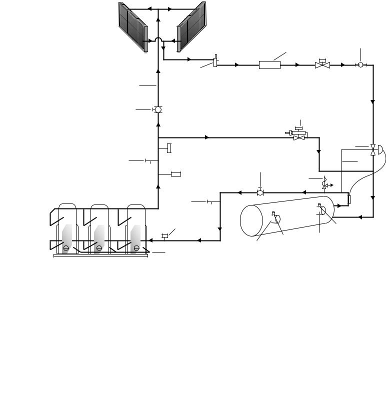
REFRIGERANT FLOW DIAGRAM
AIR COOLED CONDENSERS
|
|
YCAL REFRIGERANT FLOW DIAGRAM |
|
|
(INCLUDING TEMPERATURE SENSORS & PRESSURE TRANSDUCERS) |
||
|
|
NOTE: YCAL0040-0080 HAVE TWO REFRIGERANT |
|
|
|
SYSTEMS AND ONE DX COOLER. |
|
|
|
* HOT GAS OPTION - SYSTEM 1 ONLY |
|
|
|
|
SIGHT GLASS / |
|
LIQUID LINE FILTER / DRIER |
MOISTURE INDICATOR |
|
|
|
||
LIQUID LINE |
|
|
|
SERVICE VALVE |
|
|
LIQUID LINE |
|
|
SOLENOID VALVE |
|
HOT DISCHARGE |
|
|
|
GAS LINE |
|
|
|
DISCHARGE LINE |
|
* SOLENOID OPERATED |
|
BALL VALVE |
|
||
|
|
HOT GAS BY PASS VALVE |
|
OPTIONAL DISCHARGE |
|
|
TXV |
PRESSURE TRANSDUCER |
|
|
|
SERVICE VALVE |
|
|
EQUALIZER |
SUCTION LINE |
|
LINE |
|
|
|
|
|
HIGH PRESSURE |
BALL VALVE |
|
|
|
|
|
|
CUTOUT SWITCH |
|
RELIEF VALVE |
|
|
|
|
|
|
|
300 PSIG |
|
|
|
(20.68 BARG) |
|
SERVICE |
|
|
|
VALVE |
|
DX COOLER |
|
|
|
|
|
LOW PRESSURE SWITCH OR |
|
|
RETURN WATER |
SUCTION PRESSURE TRANSDUCER |
|
|
|
|
|
TEMP. SENSOR |
|
|
|
|
|
|
|
LEAVING |
ENTERING CHILLED WATER |
|
|
CHILLED WATER |
|
|
LEAVING CHILLED WATER |
TEMP. SENSOR |
|
OIL EQUALIZING |
|
|
|
LINE |
|
|
|
2 OR 3 COMPRESSORS PER SYSTEM
LD03844
FIG. 1 – REFRIGERANT FLOW DIAGRAM
YORK INTERNATIONAL |
9 |
Installation
INSTALLATION
To ensure warranty coverage, this equipment must be commissioned and serviced by an authorized YORK service mechanic or a qualified service person experienced in chiller installation. Installation must comply with all applicable codes, particularly in regard to electrical wiring and other safety elements such as relief valves, HP cut-out settings, design working pressures, and ventilation requirements consistent with the amount and type of refrigerant charge.
Lethal voltages exist within the control panels. Before servicing, open and tag all disconnect switches.
INSTALLATION CHECK LIST
The following items, 1 thru 5, must be checked before placing the units in operation.
1.Inspect the unit for shipping damage.
2.Rig unit using spreader bars.
3.Open the unit only to install water piping system. Do not remove protective covers from water connections until piping is ready for attachment. Check water piping to insure cleanliness.
4.Pipe unit using good piping practice (see ASHRAE handbook section 215 and 195.
5.Check to see that the unit is installed and operated within limitations (Refer to LIMITATIONS).
The following pages outline detailed procedures to be followed to install and start-up the chiller.
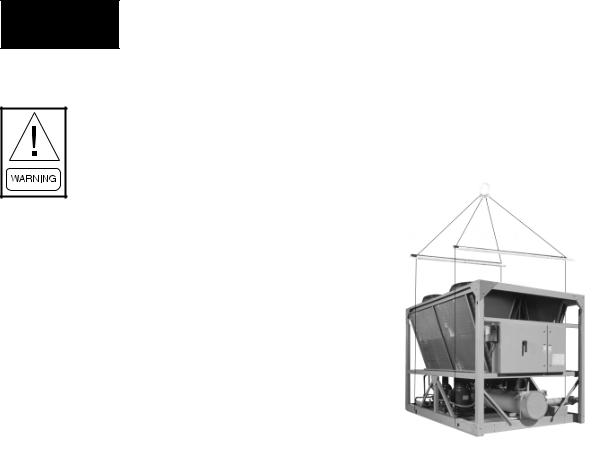
HANDLING
These units are shipped as completely assembled units containing full operating charge, and care should be taken to avoid damage due to rough handling.
The unit should be lifted by inserting hooks through the holes provided in unit base rails. Spreader bars should be used to avoid crushing the unit frame rails with the lifting chains. See below.
29224(RIG)A
INSPECTION
Immediately upon receiving the unit, it should be inspected for possible damage which may have occurred during transit. If damage is evident, it should be noted in the carrier’s freight bill. A written request for inspection by the carrier’s agent should be made at once. See “Instruction” manual, Form 50.15-NM for more information and details.
LOCATION AND CLEARANCES
These units are designed for outdoor installations on ground level, rooftop, or beside a building. Location should be selected for minimum sun exposure and to insure adequate supply of fresh air for the condenser. The units must be installed with sufficient clearances for air entrance to the condenser coil, for air discharge away from the condenser, and for servicing access.
In installations where winter operation is intended and snow accumulations are expected, additional height must be provided to insure normal condenser air flow.
Clearances are listed under “Notes” in the “DIMENSIONS” section.
10 |
YORK INTERNATIONAL |
FOUNDATION
The unit should be mounted on a flat and level foundation, floor, or rooftop capable of supporting the entire operating weight of the equipment. See PHYSICAL DATA for operating weight. If the unit is elevated beyond the normal reach of service personnel, a suitable catwalk must be capable of supporting service personnel, their equipment, and the compressors.
GROUND LEVEL LOCATIONS
It is important that the units be installed on a substantial base that will not settle. A one piece concrete slab with footers extended below the frost line is highly recommended. Additionally, the slab should not be tied to the main building foundations as noise and vibration may be transmitted. Mounting holes are provided in the steel channel for bolting the unit to its foundation. (See DIMENSIONS.)
For ground level installations, precautions should be taken to protect the unit from tampering by or injury to unauthorized persons. Screws and/or latches on access panels will prevent casual tampering. However, further safety precautions such as a fenced-in enclosure or locking devices on the panels may be advisable.
ROOFTOP LOCATIONS
Choose a spot with adequate structural strength to safely support the entire weight of the unit and service personnel. Care must be taken not to damage the roof.
Consult the building contractor or architect if the roof is bonded. Roof installations should have wooden beams (treated to reduce deterioration), cork, rubber, or vibration isolators under the base to minimize vibration.
NOISE SENSITIVE LOCATIONS
Efforts should be made to assure that the chiller is not located next to occupied spaces or noise sensitive areas where chiller noise level would be a problem. Chiller noise is a result of compressor and fan operation. Considerations should be made utilizing noise levels published in the YORK Engineering Guide for the specific chiller model. Sound blankets for the compressors and low sound fans are available.
FORM 150.62-NM1
SPRING ISOLATORS (OPTIONAL)
When ordered, four (4) isolators will be furnished.
Identify the isolator, and locate at the proper mounting
point, and adjust per instructions. See Appendix 1.
1
COMPRESSOR MOUNTING
The compressors are mounted on four (4) rubber isolators. The mounting bolts should not be loosened or adjusted at installation of the chiller.
REMOTE COOLER OPTION
For units using remote cooler option, refer to instructions included with miscellaneous cooler parts kit.
The unit is shipped with a 6 lb. (2.7 kg) holding charge. The remainder of the charge must be weighed-in according to the operating charge listed under Physical Data. Additional charge must also be added for the refrigerant lines.
CHILLED WATER PIPING
General – When the unit has been located in its final position, the unit water piping may be connected. Normal installation precautions should be observed in order to receive maximum operating efficiencies. Piping should be kept free of all foreign matter. All chilled water evaporator piping must comply in all respects with local plumbing codes and ordinances.
Since elbows, tees and valves decrease pump capacity, all piping should be kept as straight and as simple as possible possible. All piping must be supported independent of the chiller.
Consideration should be given to compressor access when laying out water piping. Routing the water piping too close to the unit could make compressor servicing/replacement difficult.
YORK INTERNATIONAL |
11 |

Installation
Hand stop valves should be installed in all lines to facilitate servicing.
Piping to the inlet and outlet connections of the chiller should include high-pressure rubber hose or piping loops to insure against transmission of water pump vibration. The necessary components must be obtained in the field.
Drain connections should be provided at all low points to permit complete drainage of the cooler and system water piping.
A small valve or valves should be installed at the highest point or points in the chilled water piping to allow any trapped air to be purged. Vent and drain connections should be extended beyond the insulation to make them accessible.
The piping to and from the cooler must be designed to suit the individual installation. It is important that the following considerations be observed:
1.The chilled liquid piping system should be laid out so that the circulating pump discharges directly into the cooler. The suction for this pump should be taken from the piping system return line and not the cooler. This piping scheme is recommended, but is not mandatory.
2.The inlet and outlet cooler connection sizes are 3" (YCAL0014 - 0030), 4" (YCAL0034 - 0060), or 6" (YCAL0064 - 0080).
3.A strainer, preferably 40 mesh, must be installed in the cooler inlet line just ahead of the cooler. This is important to protect the cooler from entrance of large particles which could cause damage to the evaporator.
4.All chilled liquid piping should be thoroughly flushed to free it from foreign material before the system is placed into operation. Use care not to flush any foreign material into or through the cooler.
5.As an aid to servicing, thermometers and pressure gauges should be installed in the inlet and outlet wa-
ter lines.
6.The chilled water lines that are exposed to outdoor ambients should be wrapped with supplemental heater cable and insulated to protect against freezeup during low ambient periods, and to prevent formation of condensation on lines in warm humid locations.
7.A chilled water flow switch, (either by YORK or others) MUST be installed in the leaving water piping of the cooler. There should be a straight horizontal run of at least 5 diameters on each side of the switch. Adjust the flow switch paddle to the size of the pipe in which it is to be installed. (See manufacturer’s instructions furnished with the switch.) The switch is to be wired to terminals 13 – 14 of CTB1 located in the control panel, as shown on the unit wiring diagram.
The Flow Switch MUST NOT be used to start and stop the chiller (i.e. starting and stopping the chilled water pump). It is intended only as a safety switch.
WIRING
Liquid Chillers are shipped with all factory mounted controls wired for operation.
Field Wiring – Power wiring must be provided through a fused disconnect switch to the unit terminals (or optional molded disconnect switch) in accordance with N.E.C. or local code requirements. Minimum circuit ampacity and maximum dual element fuse size are given in the Tables 2 – 6.
A 120-1-60, 15 amp source must be supplied for the control panel through a fused disconnect when a control panel transformer (optional) is not provided. Refer to Table 1 and Figures 2 - 4.
See Figures 2 - 5 and unit wiring diagrams for field and power wiring connections, chilled water pump starter contacts, alarm contacts, compressor run status contacts, PWM input, and load limit input. Refer to section on UNIT OPERATION for a detailed description of operation concerning aforementioned contacts and inputs.
12 |
YORK INTERNATIONAL |

EVAPORATOR PUMP START CONTACTS
Terminal block CTB2 - terminals 23 to 24, are normally open contacts that can be used to switch field supplied power to provide a start signal to the evaporator pump contactor. The contacts will be closed when any of the following conditions occur:
1.Low Leaving Chilled Liquid Fault
2.Any compressor is running.
3.Daily schedule is not programmed OFF and the Unit Switch is ON.
The pump will not run if the micropanel has been powered up for less than 30 seconds, or if the pump has run in the last 30 seconds, to prevent pump motor overheating. Refer to figure 5 and unit wiring diagram.
SYSTEM RUN CONTACTS
Contacts are available to monitor system status. Normally-open auxiliary contacts from each compressor contactor are wired in parallel with CTB2 - terminals 25 to 26 for system 1, and CTB2 - terminals 27 to 28 for system 2 (YCAL0040 - YCAL0080). Refer to Figure 5 and unit wiring diagram.
ALARM STATUS CONTACTS
Normally-open contacts are available for each refrigerant system. These normally-open contacts close when the system if functionally normally. The respective contacts will open when the unit is shut down on a unit fault, or locked out on a system fault. Field connections are at CTB2 terminals 29 to 30 (system 1), and terminals 31 to 32 (system 2 YCAL0040 - YCAL0080).
REMOTE START/STOP CONTACTS
To remotely start and stop the chiller, dry contacts can be wired in series with the flow switch and CTB1 - terminals 13 to 14. Refer to Figure 5 and unit wiring diagram.
FORM 150.62-NM1
REMOTE EMERGENCY CUTOFF
Immediate shutdown of the chiller can be accomplished by opening a field installed dry contact to break the electrical circuit between terminals 5 to L on terminal block CTB2. The unit is shipped with a factory jumper installed
between terminals 5 to L, which must be removed if 1 emergency shutdown contacts are installed. Refer to Figure 5 and unit wiring diagram.
PWM INPUT
The PWM input allows reset of the chilled liquid setpoint by supplying a “timed” contact closure. Field wiring should be connected to CTB1 - terminals 13 to 20. A detailed explanation is provided in the Unit Control section. Refer to Figure 5 and unit wiring diagram.
LOAD LIMIT INPUT
Load limiting is a feature that prevents the unit from loading beyond a desired value. The unit can be “load limited” either 33%, 50%, or 66%, depending on the number of compressors on unit. The field connections are wired to CTB1 - terminals 13 to 21, and work in conjunction with the PWM inputs. A detailed explanation is provided in the Unit Control section. Refer to figure 5 and unit wiring diagram.
When using the Load Limit feature, the PWM feature will not function - SIMULTANEOUS OPERATION OF LOAD LIMITING AND TEMPERATURE RESET (PWM INPUT) CANNOT BE DONE.
FLOW SWITCH INPUT
The flow switch is field wired to CTB1 terminals 13 - 14. See Figure 5 and unit wiring diagram.
YORK INTERNATIONAL |
13 |
Installation
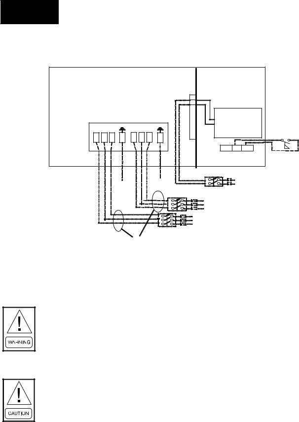
STANDARD POWER SUPPLY WIRING – (0014 - 0080)
Power Panel |
|
Control Panel |
|||
|
|
|
|
2 |
|
|
|
|
|
L |
|
Circuit # 1 *Circuit # 2 |
Micropanel |
|
|||
1L1 1L2 1L3 |
GRD |
2L1 2L2 2L3 |
GRD |
|
Flow Switch |
CTB2 |
|
||||
|
|
|
|
14 |
|
|
|
|
|
13 |
|
|
|
|
|
CTB1 |
|
|
|
|
|
Field 120-1-60 Micropanel |
|
|
|
|
|
Power Supply if control |
|
|
|
|
|
transformer not supplied |
|
|
|
|
|
Field Unit Power |
|
|
|
|
|
Supply |
|
|
See electrical note 9 |
|
|
||
|
|
|
|
|
LD04483 |
IT IS POSSIBLE THAT MULTIPLE SOURCES OF POWER CAN BE SUPPLYING THE UNIT POWER PANEL. TO PREVENT SERIOUS INJURY OR DEATH, THE TECHNICIAN SHOULD VERIFY THAT NO LETHAL VOLTAGES ARE PRESENT INSIDE THE PANEL AFTER DISCONNECTING POWER, PRIOR TO WORKING ON EQUIPMENT.
THE UNIT EVAPORATOR HEATER USES 120 VAC. DISCONNECTING 120 VAC POWER FROM THE UNIT, AT OR BELOW FREEZING TEMPERATURES, CAN RESULT IN DAMAGE TO THE EVAPORATOR AND UNIT AS A RESULT OF THE CHILLED LIQUID FREEZING.
Electrical Notes and Legend located on Page 18 and 19.
FIG. 2 – MULTI POINT POWER SUPPLY WIRING
14 |
YORK INTERNATIONAL |
FORM 150.62-NM1
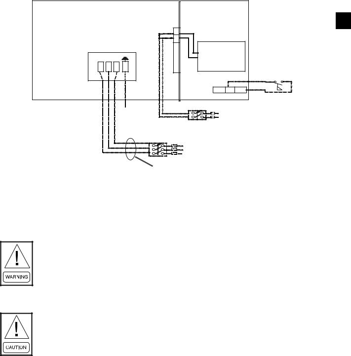
OPTIONAL SINGLE POINT POWER SUPPLY WIRING – (0040 - 0080)
Power Panel |
Control Panel |
1
|
|
|
2 |
|
|
|
|
|
L |
|
|
|
|
|
Micropanel |
|
|
1L1 |
1L2 |
1L3 |
GRD |
|
|
|
|
|
CTB2 |
|
Flow Switch |
|
|
|
|
13 |
14 |
|
|
|
|
CTB1 |
|
|
|
|
|
Field 120-1-60 Micropanel |
|
|
|
|
|
Power Supply if control |
|
|
|
|
|
transformer not supplied |
|
|
|
|
Field Unit |
Power Supply |
|
See electrical note 9
LD04484
IT IS POSSIBLE THAT MULTIPLE SOURCES OF POWER CAN BE SUPPLYING THE UNIT POWER PANEL. TO PREVENT SERIOUS INJURY OR DEATH, THE TECHNICIAN SHOULD VERIFY THAT NO LETHAL VOLTAGES ARE PRESENT INSIDE THE PANEL AFTER DISCONNECTING POWER, PRIOR TO WORKING ON EQUIPMENT.
THE UNIT EVAPORATOR HEATER USES 120 VAC. DISCONNECTING 120 VAC POWER FROM THE UNIT, AT OR BELOW FREEZING TEMPERATURES, CAN RESULT IN DAMAGE TO THE EVAPORATOR AND UNIT AS A RESULT OF THE CHILLED LIQUID FREEZING.
Electrical Notes and Legend located on Page 18 and 19.
FIG. 3 – OPTIONAL SINGLE POINT POWER SUPPLY WIRING
YORK INTERNATIONAL |
15 |
Installation
OPTIONAL SINGLE-POINT POWER SUPPLY WIRING
N-F DISC SW OR CIRC BKR (0014 - 0080)
Power Panel |
Control Panel |
|
|
|
|
2 |
|
|
|
|
|
|
L |
|
|
N-F Disconnect |
|
|
Micropanel |
|
||
Sw. OR Molded |
|
|
|
|||
|
|
|
|
|||
Case Circuit |
|
|
|
|
|
|
Bkr. |
|
|
GRD |
|
|
|
1L1 |
1L2 |
1L3 |
CTB2 |
|
Flow Switch |
|
|
|
|||||
|
|
|
|
|
|
|
|
|
|
|
|
13 |
14 |
|
|
|
|
|
CTB1 |
|
|
|
|
|
|
Field 120-1-60 Micropanel |
|
|
|
|
|
|
Power Supply if control |
|
|
|
|
|
|
transformer not supplied |
|
|
|
|
|
Field Unit |
Power |
|
|
|
|
|
Supply |
|
|
See electrical note 9
LD04485
IT IS POSSIBLE THAT MULTIPLE SOURCES OF POWER CAN BE SUPPLYING THE UNIT POWER PANEL. TO PREVENT SERIOUS INJURY OR DEATH, THE TECHNICIAN SHOULD VERIFY THAT NO LETHAL VOLTAGES ARE PRESENT INSIDE THE PANEL AFTER DISCONNECTING POWER, PRIOR TO WORKING ON EQUIPMENT.
THE UNIT EVAPORATOR HEATER USES 120 VAC. DISCONNECTING 120 VAC POWER FROM THE UNIT, AT OR BELOW FREEZING TEMPERATURES, CAN RESULT IN DAMAGE TO THE EVAPORATOR AND UNIT AS A RESULT OF THE CHILLED LIQUID FREEZING.
Electrical Notes and Legend located on Page 18 and 19.
FIG. 4 – OPTIONAL SINGLE POINT POWER WIRING
16 |
YORK INTERNATIONAL |

FORM 150.62-NM1
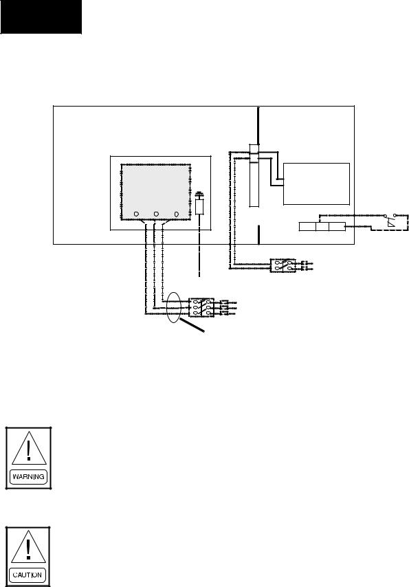
CONTROL WIRING
FLOW SW REMOTE START/STOP
13 |
1 |
|
14 |
||
|
PWM INPUT
13
20
LOAD LIMIT INPUT
13
21
CTB1 |
LD03819 |
|


 *
* 


* Factory wired with optional transformer.
LD03611
IT IS POSSIBLE THAT MULTIPLE SOURCES OF POWER CAN BE SUPPLYING THE UNIT POWER PANEL. TO PREVENT SERIOUS INJURY OR DEATH, THE TECHNICIAN SHOULD VERIFY THAT NO LETHAL VOLTAGES ARE PRESENT INSIDE THE PANEL AFTER DISCONNECTING POWER, PRIOR TO WORKING ON EQUIPMENT.
THE UNIT EVAPORATOR HEATER USES 120 VAC. DISCONNECTING 120 VAC |
|
POWER FROM THE UNIT, AT OR BELOW FREEZING TEMPERATURES, CAN |
|
RESULT IN DAMAGE TO THE EVAPORATOR AND UNIT AS A RESULT OF THE |
|
CHILLED LIQUID FREEZING. |
|
FIG. 5 – CONTROL WIRING |
|
YORK INTERNATIONAL |
17 |

Installation
ELECTRICAL NOTES
NOTES:
1.Minimum Circuit Ampacity (MCA) is based on 125% of the rated load amps for the largest motor plus 100% of the rated load amps for all other loads included in the circuit, per N.E.C. Article 430-24. If the Factory Mounted Control Transformer is provided, add the following to the system MCA values in the electrical tables for the system supplying power to the optional transformer. -17, add 2.5 amps; -28, add 2.3 amps; -40, add 1.5 amps, - 46, add 1.3 amps; -58, add 1 amp.
2.The minimum recommended disconnect switch is based on 115% of the rated load amps for all loads included in the circuit, per N.E.C. Article 440.
3.Minimum fuse size is based upon 150% of the rated load amps for the largest motor plus 100% of the rated load amps for all other loads included in the circuit to avoid nuisance trips at start-up due to lock rotor amps. It is not recommended in applications where brown outs, frequent starting and stopping of the unit, and/or operation at ambient temperatures in excess of 95 °F is anticipated.
4.Maximum fuse size is based upon 225% of the rated load amps for the largest motor plus 100% of the rated load amps for all other loads included in the circuit, per N.E.C. Article 440-22.
5.Circuit breakers must be U.L. listed and CSA certified and maximum size is based on 225% of the rated load amps for the largest motor plus 100% of the rated load amps for all other loads included in the circuit. Exception: YCA0014 and YCAL0020 must have the optional factory overloads installed to use a standard circuit breaker. Otherwise, an HACR-type circuit breakers must be used. Maximum HACR circuit breaker rating is based on 225% of the rated load amps for the largest motor plus 100% of the rated load amps for all other loads included in the circuit.
6.The “INCOMING WIRE RANGE” is the minimum and maximum wire size that can be accommodated by the unit wiring lugs. The (2) preceding the wire range indicates the number of termination points available per phase of the wire range specified. Actual wire size and number of wires per phase must be determined based on the National Electrical Code, using copper connectors only. Field wiring must also comply with local codes.
7.A ground lug is provided for each compressor system to accommodate a field grounding conductor per N.E.C. Table 250-95. A control circuit grounding lug is also supplied.
8.The supplied disconnect is a “Disconnecting Means” as defined in the N.E.C. 100, and is intended for isolating the unit for the available power supply to perform maintenance and troubleshooting. This disconnect is not intended to be a Load Break Device.
9.Field Wiring by others which complies to the National Electrical Code and Local Codes.
18 |
YORK INTERNATIONAL |

FORM 150.62-NM1
ELECTRICAL NOTES
LEGEND |
|
|
|
|
|
|
|
1 |
|
ACR-LINE |
ACROSS THE LINE START |
|
||
C.B. |
CIRCUIT BREAKER |
|
|
|
|
|
|
||
D.E. |
DUAL ELEMENT FUSE |
|
|
|
DISC SW |
DISCONNECT SWITCH |
|
|
|
FACT MOUNT CB |
FACTORY MOUNTED CIRCUIT BREAKER |
|
|
|
FLA |
FULL LOAD AMPS |
|
|
|
HZ |
HERTZ |
|
|
|
MAX |
MAXIMUM |
|
|
|
MCA |
MINIMUM CIRCUIT AMPACITY |
|
|
|
MIN |
MINIMUM |
|
|
|
MIN NF |
MINIMUM NON FUSED |
|
|
|
RLA |
RATED LOAD AMPS |
|
|
|
S.P. WIRE |
SINGLE POINT WIRING |
|
|
|
UNIT MTD SERV SW |
UNIT MOUNTED SERVICE (NON-FUSED DISCONNECT |
|
|
|
SWITCH) |
|
|
||
|
|
|
||
LRA |
LOCKED ROTOR AMPS |
|
|
|
VOLTAGE CODE
-17 = 200-3-60
-28 = 230-3-60
-40 = 380-3-60
-46 = 460-3-60
-58 = 575-3-60
LEGEND: Field Wiring
Factory Wiring
YORK INTERNATIONAL |
19 |

Installation
ELECTRICAL DATA
TABLE 1 – MICROPANEL POWER SUPPLY
|
|
|
MCA |
OVER CURRENT PROTECTION, |
|
||
UNIT VOLTAGE |
UNIT VOLTAGE |
CONTROL POWER |
|
SEE NOTE B |
NF DISC Sw |
||
|
|
||||||
|
|
|
NOTE A |
MIN |
|
MAX |
|
MODELS w/o |
|
115-1-60/50 |
15A |
10A |
|
15A |
30 A / 240V |
CONTROL TRANS |
|
|
|||||
|
|
|
|
|
|
|
|
|
-17 |
200-1-60 |
15A |
10A |
|
15A |
30 A / 240V |
MODELS w/ |
-28 |
230-1-60 |
15A |
10A |
|
15A |
30 A / 240V |
-40 |
380-1-60 |
15A |
10A |
|
15A |
30 A / 480V |
|
CONTROL TRANS |
|
||||||
-46 |
460-1-60 |
15A |
10A |
|
15A |
30 A / 480V |
|
|
|
||||||
|
-58 |
575-1-60 |
15A |
10A |
|
15A |
30 A / 600V |
|
|
|
|
|
|
|
|
A.Minimum #14 AWG, 75° C, Copper Recommended
B.Minimum and Maximum Over Current Protection, Dual Element Fuse or Circuit Breaker
IT IS POSSIBLE THAT MULTIPLE SOURCES OF POWER CAN BE SUPPLYING THE UNIT POWER PANEL. TO PREVENT SERIOUS INJURY OR DEATH, THE TECHNICIAN SHOULD VERIFY THAT NO LETHAL VOLTAGES ARE PRESENT INSIDE THE PANEL AFTER DISCONNECTING POWER, PRIOR TO WORKING ON EQUIPMENT.
THE UNIT EVAPORATOR HEATER USES 120 VAC. DISCONNECTING 120 VAC POWER FROM THE UNIT, AT OR BELOW FREEZING TEMPERATURES, CAN RESULT IN DAMAGE TO THE EVAPORATOR AND UNIT AS A RESULT OF THE CHILLED LIQUID FREEZING.
20 |
YORK INTERNATIONAL |
|
|
|
|
|
|
|
|
|
|
|
|
|
|
|
|
|
FORM 150.62-NM1 |
|
|
|||
|
|
ELECTRICAL DATA – STANDARD SINGLE POINT POWER |
|
|
|
|
||||||||||||||||
|
|
|
|
|
|
YCAL0014SC - YCAL0034SC |
|
|
|
|
|
|
|
|
|
|||||||
TABLE 2 – STANDARD SINGLE POINT POWER |
|
|
|
|
|
|
|
|
|
|
|
|
|
|||||||||
|
|
|
|
|
|
|
|
|
|
|
|
|
|
|
|
|
|
|||||
|
|
SINGLE POINT FIELD SUPPLIED WIRING |
|
|
|
SYSTEM #1 COMPRESSOR & FAN |
|
|
|
|
||||||||||||
|
|
|
|
|
|
|
|
|
|
|
|
|
|
|
|
|
|
|
|
|
|
1 |
MODEL |
|
|
|
MIN N/F |
D.E. FUSE |
CKT. BKR.5 |
INCOMING |
COMPR. #1 |
|
COMPR. #2 |
COMPR. #3 |
|
FANS |
|
||||||||
VOLT |
HZ |
MCA1 |
WIRE |
|
|
|
||||||||||||||||
YCAL |
DISC SW2 |
|
|
|
|
|
|
|
|
|
|
|
|
|
|
|
|
|
||||
|
|
|
MIN3 |
MAX4 |
MIN |
|
MAX |
RANGE6 |
RLA |
LRA |
|
RLA |
LRA |
RLA |
LRA |
|
QTY |
FLA (EA) |
|
|
||
|
|
|
|
|
|
|
|
|
|
|||||||||||||
|
200 |
60 |
75 |
100 |
90 |
100 |
90 |
|
100 |
# 4 - # 1 |
26.0 |
195 |
|
26.0 |
195 |
— |
— |
|
2 |
8.2 |
|
|
|
|
|
|
|
|
|
|
|
|
|
|
|
|
|
|
|
|
|
|
|
|
|
|
230 |
60 |
70 |
100 |
80 |
90 |
80 |
|
90 |
# 4 - # 1 |
24.1 |
195 |
|
24.1 |
195 |
— |
— |
|
2 |
7.8 |
|
|
0014SC |
|
|
|
|
|
|
|
|
|
|
|
|
|
|
|
|
|
|
|
|
|
|
380 |
60 |
42 |
60 |
45 |
50 |
45 |
|
50 |
# 8 - # 4 |
14.0 |
113 |
|
14.0 |
113 |
— |
— |
|
2 |
4.8 |
|
|
|
|
|
|
|
|
|
|
|
|
|
|
|
|
|
|
|
|
|
|
|
|
|
|
|
460 |
60 |
34 |
60 |
40 |
40 |
40 |
|
40 |
# 10 - # 6 |
11.5 |
98 |
|
11.5 |
98 |
— |
— |
|
2 |
3.8 |
|
|
|
575 |
60 |
27 |
30 |
30 |
35 |
30 |
|
35 |
# 10 - # 6 |
9.2 |
80 |
|
9.2 |
80 |
— |
— |
|
2 |
3.1 |
|
|
|
|
|
|
|
|
|
|
|
|
|
|
|
|
|
|
|
|
|
|
|
|
|
|
200 |
60 |
100 |
150 |
110 |
125 |
110 |
|
125 |
# 2 - 1/0 |
37.0 |
237 |
|
37.0 |
237 |
— |
— |
|
2 |
8.2 |
|
|
|
|
|
|
|
|
|
|
|
|
|
|
|
|
|
|
|
|
|
|
|
|
|
|
230 |
60 |
93 |
100 |
110 |
125 |
110 |
|
125 |
# 2 - 1/0 |
34.3 |
237 |
|
34.3 |
237 |
— |
— |
|
2 |
7.8 |
|
|
0020SC |
|
|
|
|
|
|
|
|
|
|
|
|
|
|
|
|
|
|
|
|
|
|
380 |
60 |
52 |
60 |
60 |
60 |
60 |
|
60 |
# 6 - # 2 |
18.5 |
154 |
|
18.5 |
154 |
— |
— |
|
2 |
4.8 |
|
|
|
|
460 |
60 |
45 |
60 |
50 |
60 |
50 |
|
60 |
# 8 - # 4 |
16.3 |
130 |
|
16.3 |
130 |
— |
— |
|
2 |
3.8 |
|
|
|
|
|
|
|
|
|
|
|
|
|
|
|
|
|
|
|
|
|
|
|
|
|
|
575 |
60 |
36 |
60 |
40 |
45 |
40 |
|
45 |
# 8 - # 4 |
13.1 |
85 |
|
13.1 |
85 |
— |
— |
|
2 |
3.1 |
|
|
|
200 |
60 |
127 |
150 |
150 |
175 |
150 |
|
175 |
# 1 - 2/0 |
49.1 |
298 |
|
49.1 |
298 |
— |
— |
|
2 |
8.2 |
|
|
|
|
|
|
|
|
|
|
|
|
|
|
|
|
|
|
|
|
|
|
|
|
|
|
230 |
60 |
118 |
150 |
150 |
150 |
150 |
|
150 |
# 1 - 2/0 |
45.5 |
298 |
|
45.5 |
298 |
— |
— |
|
2 |
7.8 |
|
|
0024SC |
|
|
|
|
|
|
|
|
|
|
|
|
|
|
|
|
|
|
|
|
|
|
380 |
60 |
76 |
100 |
90 |
100 |
90 |
|
100 |
# 4 - # 1 |
29.5 |
235 |
|
29.5 |
235 |
— |
— |
|
2 |
4.8 |
|
|
|
|
|
|
|
|
|
|
|
|
|
|
|
|
|
|
|
|
|
|
|
|
|
|
|
460 |
60 |
57 |
60 |
70 |
70 |
70 |
|
70 |
# 6 - # 2 |
21.7 |
170 |
|
21.7 |
170 |
— |
— |
|
2 |
3.8 |
|
|
|
|
|
|
|
|
|
|
|
|
|
|
|
|
|
|
|
|
|
|
|
|
|
|
575 |
60 |
46 |
60 |
50 |
60 |
50 |
|
60 |
# 8 - # 4 |
17.3 |
140 |
|
17.3 |
140 |
— |
— |
|
2 |
3.1 |
|
|
|
200 |
60 |
140 |
150 |
175 |
175 |
175 |
|
175 |
1/0 - 3/0 |
54.7 |
420 |
|
54.7 |
420 |
— |
— |
|
2 |
8.2 |
|
|
|
|
|
|
|
|
|
|
|
|
|
|
|
|
|
|
|
|
|
|
|
|
|
|
230 |
60 |
130 |
150 |
150 |
175 |
150 |
|
175 |
1/0 - 3/0 |
50.7 |
420 |
|
50.7 |
420 |
— |
— |
|
2 |
7.8 |
|
|
0030SC |
|
|
|
|
|
|
|
|
|
|
|
|
|
|
|
|
|
|
|
|
|
|
380 |
60 |
75 |
100 |
90 |
100 |
90 |
|
100 |
# 4 - # 1 |
28.7 |
235 |
|
28.7 |
235 |
— |
— |
|
2 |
4.8 |
|
|
|
|
|
|
|
|
|
|
|
|
|
|
|
|
|
|
|
|
|
|
|
|
|
|
|
460 |
60 |
62 |
100 |
70 |
80 |
70 |
|
80 |
# 6 - # 2 |
24.1 |
175 |
|
24.1 |
175 |
— |
— |
|
2 |
3.8 |
|
|
|
|
|
|
|
|
|
|
|
|
|
|
|
|
|
|
|
|
|
|
|
|
|
|
575 |
60 |
50 |
60 |
60 |
60 |
60 |
|
60 |
# 6 - # 2 |
19.3 |
140 |
|
19.3 |
140 |
— |
— |
|
2 |
3.1 |
|
|
|
200 |
60 |
183 |
200 |
200 |
225 |
200 |
|
225 |
3/0 - 250 |
51.2 |
298 |
|
51.2 |
298 |
51.2 |
298 |
|
2 |
8.2 |
|
|
|
|
|
|
|
|
|
|
|
|
|
|
|
|
|
|
|
|
|
|
|
|
|
|
230 |
60 |
170 |
200 |
200 |
200 |
200 |
|
200 |
2/0 - 4/0 |
47.4 |
298 |
|
47.4 |
298 |
47.4 |
298 |
|
2 |
7.8 |
|
|
0034SC |
|
|
|
|
|
|
|
|
|
|
|
|
|
|
|
|
|
|
|
|
|
|
380 |
60 |
103 |
150 |
110 |
125 |
110 |
|
125 |
# 2 - 1/0 |
28.7 |
235 |
|
28.7 |
235 |
28.7 |
235 |
|
2 |
4.8 |
|
|
|
|
|
|
|
|
|
|
|
|
|
|
|
|
|
|
|
|
|
|
|
|
|
|
|
460 |
60 |
81 |
100 |
90 |
100 |
90 |
|
100 |
# 4 - # 1 |
22.6 |
175 |
|
22.6 |
175 |
22.6 |
175 |
|
2 |
3.8 |
|
|
|
|
|
|
|
|
|
|
|
|
|
|
|
|
|
|
|
|
|
|
|
|
|
|
575 |
60 |
65 |
100 |
70 |
80 |
70 |
|
80 |
# 4 - # 1 |
18 |
140 |
|
18 |
140 |
18 |
140 |
|
2 |
3.1 |
|
|
See notes and legend on pages 18 and 19.
YORK INTERNATIONAL |
21 |

Installation
ELECTRICAL DATA – STANDARD DUAL POINT POWER
YCAL0040SC - YCAL0080SC
TABLE 3 – STANDARD DUAL POINT POWER
|
|
|
SYSTEM #1 FIELD SUPPLIED WIRING |
|
|
|
SYSTEM #1 COMPRESSOR & FAN |
|
|
||||||||||
MODEL |
|
|
|
|
|
D.E. FUSE |
CKT. BKR.5 |
INCOMING |
COMPR. #1 |
COMPR. #2 |
COMPR. #3 |
|
FANS |
||||||
VOLT |
HZ |
|
MCA1 |
MIN N/F |
WIRE |
|
|||||||||||||
YCAL |
|
|
|
|
|
|
|
|
|
|
|
|
|
|
|||||
|
|
|
|
DISC SW2 |
MIN3 |
MAX4 |
MIN |
MAX |
RANGE6 |
RLA |
LRA |
RLA |
LRA |
RLA |
LRA |
|
QTY |
FLA (EA) |
|
|
|
|
|
|
|
||||||||||||||
|
200 |
60 |
|
91 |
100 |
100 |
110 |
100 |
110 |
# 2 - 1/0 |
32.9 |
265 |
32.9 |
265 |
— |
— |
|
2 |
8.2 |
|
230 |
60 |
|
85 |
100 |
100 |
110 |
100 |
110 |
# 4 - # 1 |
30.5 |
265 |
30.5 |
265 |
— |
— |
|
2 |
7.8 |
0040SC |
|
|
|
|
|
|
|
|
|
|
|
|
|
|
|
|
|
|
|
380 |
60 |
|
54 |
60 |
60 |
70 |
60 |
70 |
# 6 - # 2 |
19.4 |
155 |
19.4 |
155 |
— |
— |
|
2 |
4.8 |
|
|
|
|
|
|
|
|
|
|
|
|
|
|
|
|
|
|
|
|
|
|
460 |
60 |
|
41 |
60 |
45 |
50 |
45 |
50 |
# 8 - # 4 |
14.5 |
120 |
14.5 |
120 |
— |
— |
|
2 |
3.8 |
|
575 |
60 |
|
33 |
60 |
40 |
40 |
40 |
40 |
# 10 - # 6 |
11.6 |
80 |
11.6 |
80 |
— |
— |
|
2 |
3.1 |
|
|
|
|
|
|
|
|
|
|
|
|
|
|
|
|
|
|
|
|
|
200 |
60 |
|
130 |
150 |
150 |
175 |
150 |
175 |
# 1 - 2/0 |
50.2 |
298 |
50.2 |
298 |
— |
— |
|
2 |
8.2 |
|
|
|
|
|
|
|
|
|
|
|
|
|
|
|
|
|
|
|
|
|
230 |
60 |
|
121 |
150 |
150 |
150 |
150 |
150 |
# 1 - 2/0 |
46.5 |
298 |
46.5 |
298 |
— |
— |
|
2 |
7.8 |
0044SC |
|
|
|
|
|
|
|
|
|
|
|
|
|
|
|
|
|
|
|
380 |
60 |
|
73 |
100 |
80 |
100 |
80 |
100 |
# 4 - # 1 |
28.1 |
235 |
28.1 |
235 |
— |
— |
|
2 |
4.8 |
|
|
460 |
60 |
|
58 |
60 |
70 |
70 |
70 |
70 |
# 6 - # 2 |
22.1 |
170 |
22.1 |
170 |
— |
— |
|
2 |
3.8 |
|
|
|
|
|
|
|
|
|
|
|
|
|
|
|
|
|
|
|
|
|
575 |
60 |
|
47 |
60 |
60 |
60 |
60 |
60 |
# 8 - # 4 |
17.7 |
140 |
17.7 |
140 |
— |
— |
|
2 |
3.1 |
|
200 |
60 |
|
146 |
200 |
175 |
200 |
175 |
200 |
1/0 - 3/0 |
57.4 |
420 |
57.4 |
420 |
— |
— |
|
2 |
8.2 |
|
230 |
60 |
|
136 |
150 |
150 |
175 |
150 |
175 |
1/0 - 3/0 |
53.1 |
420 |
53.1 |
420 |
— |
— |
|
2 |
7.8 |
0050SC |
|
|
|
|
|
|
|
|
|
|
|
|
|
|
|
|
|
|
|
380 |
60 |
|
79 |
100 |
90 |
100 |
90 |
100 |
# 4 - # 1 |
30.8 |
235 |
30.8 |
235 |
— |
— |
|
2 |
4.8 |
|
|
|
|
|
|
|
|
|
|
|
|
|
|
|
|
|
|
|
|
|
|
460 |
60 |
|
65 |
100 |
80 |
80 |
80 |
80 |
# 4 - # 1 |
25.3 |
175 |
25.3 |
175 |
— |
— |
|
2 |
3.8 |
|
|
|
|
|
|
|
|
|
|
|
|
|
|
|
|
|
|
|
|
|
575 |
60 |
|
52 |
60 |
60 |
70 |
60 |
70 |
# 6 - # 2 |
20.2 |
140 |
20.2 |
140 |
— |
— |
|
2 |
3.1 |
|
200 |
60 |
|
141 |
150 |
175 |
175 |
175 |
175 |
1/0 - 3/0 |
55.0 |
420 |
55.0 |
420 |
— |
— |
|
2 |
8.2 |
|
230 |
60 |
|
131 |
150 |
150 |
175 |
150 |
175 |
1/0 - 3/0 |
50.9 |
420 |
50.9 |
420 |
— |
— |
|
2 |
7.8 |
0060SC |
|
|
|
|
|
|
|
|
|
|
|
|
|
|
|
|
|
|
|
380 |
60 |
|
77 |
100 |
90 |
100 |
90 |
100 |
# 4 - # 1 |
29.6 |
235 |
29.6 |
235 |
— |
— |
|
2 |
4.8 |
|
|
|
|
|
|
|
|
|
|
|
|
|
|
|
|
|
|
|
|
|
|
460 |
60 |
|
63 |
100 |
70 |
80 |
70 |
80 |
# 6 - # 2 |
24.2 |
175 |
24.2 |
175 |
— |
— |
|
2 |
3.8 |
|
575 |
60 |
|
50 |
60 |
60 |
60 |
60 |
60 |
# 6 - # 2 |
19.4 |
140 |
19.4 |
140 |
— |
— |
|
2 |
3.1 |
|
200 |
60 |
|
187 |
200 |
200 |
225 |
200 |
225 |
3/0 - 250 |
52.4 |
298 |
52.4 |
298 |
52.4 |
298 |
|
2 |
8.2 |
|
|
|
|
|
|
|
|
|
|
|
|
|
|
|
|
|
|
|
|
|
230 |
60 |
|
174 |
200 |
200 |
200 |
200 |
200 |
2/0 - 4/0 |
48.6 |
298 |
48.6 |
298 |
48.6 |
298 |
|
2 |
7.8 |
0064SC |
380 |
60 |
|
105 |
150 |
125 |
125 |
125 |
125 |
# 2 - 1/0 |
29.3 |
235 |
29.3 |
235 |
29.3 |
235 |
|
2 |
4.8 |
|
|
|
|
|
|
|
|
|
|
|
|
|
|
|
|
|
|
|
|
|
460 |
60 |
|
83 |
100 |
90 |
100 |
90 |
100 |
# 4 - # 1 |
23.1 |
170 |
23.1 |
170 |
23.1 |
170 |
|
2 |
3.8 |
|
|
|
|
|
|
|
|
|
|
|
|
|
|
|
|
|
|
|
|
|
575 |
60 |
|
67 |
100 |
80 |
80 |
80 |
80 |
# 4 - # 1 |
18.5 |
140 |
18.5 |
140 |
18.5 |
140 |
|
2 |
3.1 |
|
200 |
60 |
|
185 |
200 |
200 |
225 |
200 |
225 |
3/0 - 250 |
51.8 |
298 |
51.8 |
298 |
51.8 |
298 |
|
2 |
8.2 |
|
230 |
60 |
|
172 |
200 |
200 |
200 |
200 |
200 |
2/0 - 4/0 |
48.0 |
298 |
48.0 |
298 |
48.0 |
298 |
|
2 |
7.8 |
0070SC |
|
|
|
|
|
|
|
|
|
|
|
|
|
|
|
|
|
|
|
380 |
60 |
|
104 |
150 |
125 |
125 |
125 |
125 |
# 2 - 1/0 |
29.0 |
235 |
29.0 |
235 |
29.0 |
235 |
|
2 |
4.8 |
|
|
|
|
|
|
|
|
|
|
|
|
|
|
|
|
|
|
|
|
|
|
460 |
60 |
|
82 |
100 |
90 |
100 |
90 |
100 |
# 4 - # 1 |
22.9 |
170 |
22.9 |
170 |
22.9 |
170 |
|
2 |
3.8 |
|
|
|
|
|
|
|
|
|
|
|
|
|
|
|
|
|
|
|
|
|
575 |
60 |
|
66 |
100 |
80 |
80 |
80 |
80 |
# 4 - # 1 |
18.3 |
140 |
18.3 |
140 |
18.3 |
140 |
|
2 |
3.1 |
|
|
|
|
|
|
|
|
|
|
|
|
|
|
|
|
|
|
|
|
|
200 |
60 |
|
208 |
250 |
225 |
250 |
225 |
250 |
4/0 - 300 |
58.9 |
420 |
58.9 |
420 |
58.9 |
420 |
|
2 |
8.2 |
|
230 |
60 |
|
193 |
250 |
225 |
225 |
225 |
225 |
3/0 - 250 |
54.5 |
420 |
54.5 |
420 |
54.5 |
420 |
|
2 |
7.8 |
0074SC |
|
|
|
|
|
|
|
|
|
|
|
|
|
|
|
|
|
|
|
380 |
60 |
|
113 |
150 |
125 |
125 |
125 |
125 |
# 2 - 1/0 |
31.6 |
235 |
31.6 |
235 |
31.6 |
235 |
|
2 |
4.8 |
|
|
|
|
|
|
|
|
|
|
|
|
|
|
|
|
|
|
|
|
|
|
460 |
60 |
|
92 |
100 |
100 |
110 |
100 |
110 |
# 2 - 1/0 |
26.0 |
175 |
26.0 |
175 |
26.0 |
175 |
|
2 |
3.8 |
|
575 |
60 |
|
74 |
100 |
80 |
90 |
80 |
90 |
# 4 - # 1 |
20.8 |
140 |
20.8 |
140 |
20.8 |
140 |
|
2 |
3.1 |
|
200 |
60 |
|
207 |
250 |
225 |
250 |
225 |
250 |
4/0 - 300 |
58.6 |
420 |
58.6 |
420 |
58.6 |
420 |
|
2 |
8.2 |
|
|
|
|
|
|
|
|
|
|
|
|
|
|
|
|
|
|
|
|
|
230 |
60 |
|
192 |
250 |
225 |
225 |
225 |
225 |
3/0 - 250 |
54.2 |
420 |
54.2 |
420 |
54.2 |
420 |
|
2 |
7.8 |
0080SC |
380 |
60 |
|
112 |
150 |
125 |
125 |
125 |
125 |
# 2 - 1/0 |
31.5 |
235 |
31.5 |
235 |
31.5 |
235 |
|
2 |
4.8 |
|
|
|
|
|
|
|
|
|
|
|
|
|
|
|
|
|
|
|
|
|
460 |
60 |
|
92 |
100 |
100 |
110 |
100 |
110 |
# 2 - 1/0 |
25.8 |
175 |
25.8 |
175 |
25.8 |
175 |
|
2 |
3.8 |
|
|
|
|
|
|
|
|
|
|
|
|
|
|
|
|
|
|
|
|
|
575 |
60 |
|
74 |
100 |
80 |
90 |
80 |
90 |
# 4 - # 1 |
20.7 |
140 |
20.7 |
140 |
20.7 |
140 |
|
2 |
3.1 |
See notes and legend on pages 18 and 19.
22 |
YORK INTERNATIONAL |

FORM 150.62-NM1
ELECTRICAL DATA – STANDARD DUAL POINT POWER
YCAL0040SC - YCAL0080SC
|
SYSTEM #2 FIELD SUPPLIED WIRING |
|
|
|
SYSTEM #2 COMPRESSOR & FAN |
|
|
|
|
||||||||||
|
|
|
|
|
|
|
|
|
|
|
|
|
|
|
|
|
|
|
1 |
|
MIN N/F |
D.E. FUSE |
CKT. BRK.5 |
INCOMING |
COMPR. #1 |
|
COMPR. #2 |
COMPR. #3 |
|
FANS |
|
||||||||
MCA1 |
WIRE |
|
|
|
|||||||||||||||
|
|
|
|
|
|
|
|
|
|
|
|
|
|
|
|
|
|
||
|
DISC SW2 |
MIN3 |
|
MAX4 |
MIN |
|
MAX |
|
|
|
|
|
|
|
|
|
|
|
|
|
|
|
RANGE6 |
RLA |
LRA |
|
RLA |
LRA |
RLA |
LRA |
QTY |
FLA (EA) |
|
|
|||||
91 |
100 |
100 |
|
110 |
100 |
|
110 |
# 2 - 1/0 |
32.9 |
265 |
|
32.9 |
265 |
— |
— |
2 |
8.2 |
|
|
85 |
100 |
100 |
|
110 |
100 |
|
110 |
# 4 - # 1 |
30.5 |
265 |
|
30.5 |
265 |
— |
— |
2 |
7.8 |
|
|
54 |
60 |
60 |
|
70 |
60 |
|
70 |
# 6 - # 2 |
19.4 |
155 |
|
19.4 |
155 |
— |
— |
2 |
4.8 |
|
|
|
|
|
|
|
|
|
|
|
|
|
|
|
|
|
|
|
|
|
|
41 |
60 |
45 |
|
50 |
45 |
|
50 |
# 8 - # 4 |
14.5 |
120 |
|
14.5 |
120 |
— |
— |
2 |
3.8 |
|
|
33 |
60 |
40 |
|
40 |
40 |
|
40 |
# 10 - # 6 |
11.6 |
80 |
|
11.6 |
80 |
— |
— |
2 |
3.1 |
|
|
|
|
|
|
|
|
|
|
|
|
|
|
|
|
|
|
|
|
|
|
130 |
150 |
150 |
|
175 |
150 |
|
175 |
# 1 - 2/0 |
50.2 |
298 |
|
50.2 |
298 |
— |
— |
2 |
8.2 |
|
|
121 |
150 |
150 |
|
150 |
150 |
|
150 |
# 1 - 2/0 |
46.5 |
298 |
|
46.5 |
298 |
— |
— |
2 |
7.8 |
|
|
73 |
100 |
80 |
|
100 |
80 |
|
100 |
# 4 - # 1 |
28.1 |
235 |
|
28.1 |
235 |
— |
— |
2 |
4.8 |
|
|
58 |
60 |
70 |
|
70 |
70 |
|
70 |
# 6 - # 2 |
22.1 |
170 |
|
22.1 |
170 |
— |
— |
2 |
3.8 |
|
|
47 |
60 |
60 |
|
60 |
60 |
|
60 |
# 8 - # 4 |
17.7 |
140 |
|
17.7 |
140 |
— |
— |
2 |
3.1 |
|
|
130 |
150 |
150 |
|
175 |
150 |
|
175 |
# 1 - 2/0 |
49.5 |
298 |
|
49.5 |
298 |
— |
— |
2 |
8.2 |
|
|
121 |
150 |
150 |
|
150 |
150 |
|
150 |
# 1 - 2/0 |
45.9 |
298 |
|
45.9 |
298 |
— |
— |
2 |
7.8 |
|
|
|
|
|
|
|
|
|
|
|
|
|
|
|
|
|
|
|
|
|
|
73 |
100 |
80 |
|
100 |
80 |
|
100 |
# 4 - # 1 |
27.8 |
235 |
|
27.8 |
235 |
— |
— |
2 |
4.8 |
|
|
58 |
60 |
70 |
|
70 |
70 |
|
70 |
# 6 - # 2 |
21.8 |
170 |
|
21.8 |
170 |
— |
– |
2 |
3.8 |
|
|
47 |
60 |
60 |
|
60 |
60 |
|
60 |
# 8 - # 4 |
17.5 |
140 |
|
17.5 |
140 |
— |
— |
2 |
3.1 |
|
|
141 |
150 |
175 |
|
175 |
175 |
|
175 |
1/0 - 3/0 |
55.0 |
420 |
|
55.0 |
420 |
— |
— |
2 |
8.2 |
|
|
131 |
150 |
150 |
|
175 |
150 |
|
175 |
1/0 - 3/0 |
50.9 |
420 |
|
50.9 |
420 |
— |
— |
2 |
7.8 |
|
|
77 |
100 |
90 |
|
100 |
90 |
|
100 |
# 4 - # 1 |
29.6 |
235 |
|
29.6 |
235 |
— |
— |
2 |
4.8 |
|
|
|
|
|
|
|
|
|
|
|
|
|
|
|
|
|
|
|
|
|
|
63 |
100 |
70 |
|
80 |
70 |
|
80 |
# 6 - # 2 |
24.2 |
175 |
|
24.2 |
175 |
— |
— |
2 |
3.8 |
|
|
50 |
60 |
60 |
|
60 |
60 |
|
60 |
# 6 - # 2 |
19.4 |
140 |
|
19.4 |
140 |
— |
— |
2 |
3.1 |
|
|
128 |
150 |
150 |
|
150 |
150 |
|
150 |
# 1 - 2/0 |
34.2 |
265 |
|
34.2 |
265 |
34.2 |
265 |
2 |
8.2 |
|
|
|
|
|
|
|
|
|
|
|
|
|
|
|
|
|
|
|
|
|
|
119 |
150 |
150 |
|
150 |
150 |
|
150 |
# 1 - 2/0 |
31.6 |
265 |
|
31.6 |
265 |
31.6 |
265 |
2 |
7.8 |
|
|
76 |
100 |
90 |
|
90 |
90 |
|
90 |
# 4 - # 1 |
20.2 |
155 |
|
20.2 |
155 |
20.2 |
155 |
2 |
4.8 |
|
|
|
|
|
|
|
|
|
|
|
|
|
|
|
|
|
|
|
|
|
|
57 |
100 |
70 |
|
70 |
70 |
|
70 |
# 6 - # 2 |
15.1 |
120 |
|
15.1 |
120 |
15.1 |
120 |
2 |
3.8 |
|
|
|
|
|
|
|
|
|
|
|
|
|
|
|
|
|
|
|
|
|
|
46 |
60 |
50 |
|
50 |
50 |
|
50 |
# 8 - # 4 |
12.0 |
80 |
|
12.0 |
80 |
12.0 |
80 |
2 |
3.1 |
|
|
185 |
200 |
200 |
|
225 |
200 |
|
225 |
3/0 - 250 |
51.8 |
298 |
|
51.8 |
298 |
51.8 |
298 |
2 |
8.2 |
|
|
172 |
200 |
200 |
|
200 |
200 |
|
200 |
2/0 - 4/0 |
48.0 |
298 |
|
48.0 |
298 |
48.0 |
298 |
2 |
7.8 |
|
|
104 |
150 |
125 |
|
125 |
125 |
|
125 |
# 2 - 1/0 |
29.0 |
235 |
|
29.0 |
235 |
29.0 |
235 |
2 |
4.8 |
|
|
82 |
100 |
90 |
|
100 |
90 |
|
100 |
# 4 - # 1 |
22.9 |
170 |
|
22.9 |
170 |
22.9 |
170 |
2 |
3.8 |
|
|
66 |
100 |
80 |
|
80 |
80 |
|
80 |
# 4 - # 1 |
18.3 |
140 |
|
18.3 |
140 |
18.3 |
140 |
2 |
3.1 |
|
|
|
|
|
|
|
|
|
|
|
|
|
|
|
|
|
|
|
|
|
|
181 |
200 |
200 |
|
225 |
200 |
|
225 |
3/0 - 250 |
50.5 |
298 |
|
50.5 |
298 |
50.5 |
298 |
2 |
8.2 |
|
|
168 |
200 |
200 |
|
200 |
200 |
|
200 |
2/0 - 4/0 |
46.8 |
298 |
|
46.8 |
298 |
46.8 |
298 |
2 |
7.8 |
|
|
|
|
|
|
|
|
|
|
|
|
|
|
|
|
|
|
|
|
|
|
102 |
150 |
110 |
|
125 |
110 |
|
125 |
# 2 - 1/0 |
28.3 |
235 |
|
28.3 |
235 |
28.3 |
235 |
2 |
4.8 |
|
|
|
|
|
|
|
|
|
|
|
|
|
|
|
|
|
|
|
|
|
|
80 |
100 |
90 |
|
100 |
90 |
|
100 |
# 4 - # 1 |
22.3 |
170 |
|
22.3 |
170 |
22.3 |
170 |
2 |
3.8 |
|
|
65 |
100 |
70 |
|
80 |
70 |
|
80 |
# 6 - # 2 |
17.8 |
140 |
|
17.8 |
140 |
17.8 |
140 |
2 |
3.1 |
|
|
207 |
250 |
225 |
|
250 |
225 |
|
250 |
4/0 - 300 |
58.6 |
420 |
|
58.6 |
420 |
58.6 |
420 |
2 |
8.2 |
|
|
|
|
|
|
|
|
|
|
|
|
|
|
|
|
|
|
|
|
|
|
192 |
250 |
225 |
|
225 |
225 |
|
225 |
3/0 - 250 |
54.2 |
420 |
|
54.2 |
420 |
54.2 |
420 |
2 |
7.8 |
|
|
112 |
150 |
125 |
|
125 |
125 |
|
125 |
# 2 - 1/0 |
31.5 |
235 |
|
31.5 |
235 |
31.5 |
235 |
2 |
4.8 |
|
|
92 |
100 |
100 |
|
110 |
100 |
|
110 |
# 2 - 1/0 |
25.8 |
175 |
|
25.8 |
175 |
25.8 |
175 |
2 |
3.8 |
|
|
|
|
|
|
|
|
|
|
|
|
|
|
|
|
|
|
|
|
|
|
74 |
100 |
80 |
|
90 |
80 |
|
90 |
# 4 - # 1 |
20.7 |
140 |
|
20.7 |
140 |
20.7 |
140 |
2 |
3.1 |
|
|
YORK INTERNATIONAL |
23 |

Installation
ELECTRICAL DATA – OPTIONAL SINGLE POINT POWER
YCAL0014SC - YCAL0034SC
TABLE 4 – OPTIONAL SINGLE POINT POWER
SINGLE POINT FIELD SUPPLIED WIRING
MODEL |
|
|
|
MIN N/F |
D.E. FUSE |
CKT. BKR.5 |
INCOMING WIRE RANGE6 |
||||
VOLT |
HZ |
MCA1 |
FACTORY SUPPLIED OPTIONAL |
||||||||
YCAL |
DISC SW2 |
|
|
|
|
||||||
|
|
|
MIN3 |
MAX4 |
MIN |
MAX |
DISCONNECT |
BREAKER |
|||
|
|
|
|
|
|||||||
|
200 |
60 |
75 |
100 |
90 |
100 |
90 |
100 |
# 4 - # 1 |
# 4 - # 1 |
|
|
230 |
60 |
70 |
100 |
80 |
90 |
80 |
90 |
# 4 - # 1 |
# 4 - # 1 |
|
0014SC |
380 |
60 |
42 |
60 |
45 |
50 |
45 |
50 |
# 8 - # 4 |
# 8 - # 4 |
|
|
460 |
60 |
34 |
60 |
40 |
40 |
40 |
40 |
# 10 - # 6 |
# 10 - # 6 |
|
|
575 |
60 |
27 |
30 |
30 |
35 |
30 |
35 |
# 10 - # 6 |
# 10 - # 6 |
|
|
200 |
60 |
100 |
150 |
110 |
125 |
110 |
125 |
# 2 - 1/0 |
# 2 - 1/0 |
|
|
230 |
60 |
93 |
100 |
110 |
125 |
110 |
125 |
# 2 - 1/0 |
# 2 - 1/0 |
|
0020SC |
380 |
60 |
52 |
60 |
60 |
60 |
60 |
60 |
# 6 - # 2 |
# 6 - # 2 |
|
|
460 |
60 |
45 |
60 |
50 |
60 |
50 |
60 |
# 8 - # 4 |
# 8 - # 4 |
|
|
575 |
60 |
36 |
60 |
40 |
45 |
40 |
45 |
# 8 - # 4 |
# 8 - # 4 |
|
|
200 |
60 |
127 |
150 |
150 |
175 |
150 |
175 |
# 1 - 2/0 |
# 1 - 2/0 |
|
|
230 |
60 |
118 |
150 |
150 |
150 |
150 |
150 |
# 1 - 2/0 |
# 1 - 2/0 |
|
0024SC |
380 |
60 |
76 |
100 |
90 |
100 |
90 |
100 |
# 4 - # 1 |
# 4 - # 1 |
|
|
460 |
60 |
57 |
60 |
70 |
70 |
70 |
70 |
# 6 - # 2 |
# 6 - # 2 |
|
|
575 |
60 |
46 |
60 |
50 |
60 |
50 |
60 |
# 8 - # 4 |
# 8 - # 4 |
|
|
200 |
60 |
140 |
150 |
175 |
175 |
175 |
175 |
1/0 - 3/0 |
1/0 - 3/0 |
|
|
|
|
|
|
|
|
|
|
|
|
|
|
230 |
60 |
130 |
150 |
150 |
175 |
150 |
175 |
1/0 - 3/0 |
1/0 - 3/0 |
|
0030SC |
380 |
60 |
75 |
100 |
90 |
100 |
90 |
100 |
# 4 - # 1 |
# 4 - # 1 |
|
|
|
|
|
|
|
|
|
|
|
|
|
|
460 |
60 |
62 |
100 |
70 |
80 |
70 |
80 |
# 6 - # 2 |
# 6 - # 2 |
|
|
|
|
|
|
|
|
|
|
|
|
|
|
575 |
60 |
50 |
60 |
60 |
60 |
60 |
60 |
# 6 - # 2 |
# 6 - # 2 |
|
|
200 |
60 |
183 |
200 |
200 |
225 |
200 |
225 |
3/0 - 250 |
3/0 - 250 |
|
|
|
|
|
|
|
|
|
|
|
|
|
|
230 |
60 |
170 |
200 |
200 |
200 |
200 |
200 |
2/0 - 4/0 |
2/0 - 4/0 |
|
0034SC |
|
|
|
|
|
|
|
|
|
|
|
380 |
60 |
103 |
150 |
110 |
125 |
110 |
125 |
# 2 - 1/0 |
# 2 - 1/0 |
||
|
460 |
60 |
81 |
100 |
90 |
100 |
90 |
100 |
# 4 - # 1 |
# 4 - # 1 |
|
|
|
|
|
|
|
|
|
|
|
|
|
|
575 |
60 |
65 |
100 |
70 |
80 |
70 |
80 |
# 4 - # 1 |
# 4 - # 1 |
|
See notes and legend on pages 18 and 19.
24 |
YORK INTERNATIONAL |

FORM 150.62-NM1
ELECTRICAL DATA – OPTIONAL SINGLE POINT POWER
YCAL0014SC - YCAL0034SC
|
|
SYSTEM #1 COMPRESSOR & FAN |
|
|
|
|
|
1 |
||||
|
|
|
|
|
|
|
|
|
|
|
||
COMPR. #1 |
COMPR. #2 |
COMPR. #3 |
|
|
FANS |
|
||||||
|
|
|
||||||||||
|
|
|
||||||||||
RLA |
LRA |
RLA |
LRA |
RLA |
LRA |
|
QTY |
|
FLA (EA) |
|||
26.0 |
195 |
26.0 |
195 |
— |
— |
|
2 |
|
8.2 |
|
|
|
24.1 |
195 |
24.1 |
195 |
— |
— |
|
2 |
|
7.8 |
|
|
|
14.0 |
113 |
14.0 |
113 |
— |
— |
|
2 |
|
4.8 |
|
|
|
11.5 |
98 |
11.5 |
98 |
— |
— |
|
2 |
|
3.8 |
|
|
|
9.2 |
80 |
9.2 |
80 |
— |
— |
|
2 |
|
3.1 |
|
|
|
37.0 |
237 |
37.0 |
237 |
— |
— |
|
2 |
|
8.2 |
|
|
|
34.3 |
237 |
34.3 |
237 |
— |
— |
|
2 |
|
7.8 |
|
|
|
18.5 |
154 |
18.5 |
154 |
— |
— |
|
2 |
|
4.8 |
|
|
|
16.3 |
130 |
16.3 |
130 |
— |
— |
|
2 |
|
3.8 |
|
|
|
13.1 |
85 |
13.1 |
85 |
— |
— |
|
2 |
|
3.1 |
|
|
|
49.1 |
298 |
49.1 |
298 |
— |
— |
|
2 |
|
8.2 |
|
|
|
45.5 |
298 |
45.5 |
298 |
— |
— |
|
2 |
|
7.8 |
|
|
|
29.5 |
235 |
29.5 |
235 |
— |
— |
|
2 |
|
4.8 |
|
|
|
21.7 |
170 |
21.7 |
170 |
— |
— |
|
2 |
|
3.8 |
|
|
|
17.3 |
140 |
17.3 |
140 |
— |
— |
|
2 |
|
3.1 |
|
|
|
54.7 |
420 |
54.7 |
420 |
— |
— |
|
2 |
|
8.2 |
|
|
|
50.7 |
420 |
50.7 |
420 |
— |
— |
|
2 |
|
7.8 |
|
|
|
28.7 |
235 |
28.7 |
235 |
— |
— |
|
2 |
|
4.8 |
|
|
|
24.1 |
175 |
24.1 |
175 |
— |
— |
|
2 |
|
3.8 |
|
|
|
19.3 |
140 |
19.3 |
140 |
— |
— |
|
2 |
|
3.1 |
|
|
|
51.2 |
298 |
51.2 |
298 |
51.2 |
298 |
|
2 |
|
8.2 |
|
|
|
47.4 |
298 |
47.4 |
298 |
47.4 |
298 |
|
2 |
|
7.8 |
|
|
|
28.7 |
235 |
28.7 |
235 |
28.7 |
235 |
|
2 |
|
4.8 |
|
|
|
22.6 |
175 |
22.6 |
175 |
22.6 |
175 |
|
2 |
|
3.8 |
|
|
|
18 |
140 |
18 |
140 |
18 |
140 |
|
2 |
|
3.1 |
|
|
|
YORK INTERNATIONAL |
25 |

Installation
ELECTRICAL DATA – OPTIONAL SINGLE POINT POWER
YCAL0040SC - YCAL0060SC
TABLE 5 – OPTIONAL SINGLE POINT POWER
SINGLE POINT FIELD SUPPLIED WIRING
MODEL |
|
|
|
MIN N/F |
D.E. FUSE |
CKT. BKR.5 |
INCOMING WIRE RANGE6 |
|
|||||
VOLT |
HZ |
MCA1 |
FACTORY SUPPLIED OPTIONAL |
|
|||||||||
YCAL |
DISC SW2 |
|
|
|
|
|
|||||||
|
|
|
MIN3 |
MAX4 |
MIN |
MAX |
SINGLE POINT |
DISCONNECT |
BREAKER |
||||
|
|
|
|
|
|||||||||
|
200 |
60 |
173 |
200 |
200 |
200 |
200 |
200 |
2/0 - 4/0 |
2/0 - 4/0 |
2/0 - 4/0 |
||
|
|
|
|
|
|
|
|
|
|
|
|
||
|
230 |
60 |
161 |
200 |
175 |
175 |
175 |
175 |
2/0 - 4/0 |
2/0 - 4/0 |
2/0 - 4/0 |
||
0040SC |
|
|
|
|
|
|
|
|
|
|
|
||
380 |
60 |
102 |
150 |
110 |
110 |
110 |
110 |
# 2 - 1/0 |
# 2 - 1/0 |
# 2 - 1/0 |
|||
|
|
|
|
|
|
|
|
|
|
|
|
||
|
460 |
60 |
77 |
100 |
90 |
90 |
90 |
90 |
# 4 - # 1 |
# 4 - # 1 |
# 4 - # 1 |
||
|
575 |
60 |
62 |
100 |
70 |
70 |
70 |
70 |
# 6 - # 2 |
# 6 - # 2 |
# 6 - # 2 |
||
|
200 |
60 |
247 |
400 |
300 |
300 |
300 |
300 |
250 - 350 |
250 |
- 350 |
250 |
- 350 |
|
|
|
|
|
|
|
|
|
|
|
|
||
|
230 |
60 |
229 |
250 |
250 |
250 |
250 |
250 |
4/0 - 300 |
4/0 - 300 |
4/0 - 300 |
||
0044SC |
|
|
|
|
|
|
|
|
|
|
|
||
380 |
60 |
139 |
200 |
150 |
150 |
150 |
150 |
1/0 - 3/0 |
1/0 - 3/0 |
1/0 - 3/0 |
|||
|
|
|
|
|
|
|
|
|
|
|
|
||
|
460 |
60 |
110 |
150 |
125 |
125 |
125 |
125 |
# 2 - 1/0 |
# 2 - 1/0 |
# 2 - 1/0 |
||
|
|
|
|
|
|
|
|
|
|
|
|
||
|
575 |
60 |
88 |
100 |
100 |
100 |
100 |
100 |
# 2 - 1/0 |
# 2 - 1/0 |
# 2 - 1/0 |
||
|
200 |
60 |
261 |
400 |
300 |
300 |
300 |
300 |
300 - 400 |
300 |
- 400 |
300 |
- 400 |
|
|
|
|
|
|
|
|
|
|
|
|
|
|
|
230 |
60 |
243 |
400 |
300 |
300 |
300 |
300 |
250 - 350 |
250 |
- 350 |
250 |
- 350 |
0050SC |
|
|
|
|
|
|
|
|
|
|
|
|
|
380 |
60 |
145 |
200 |
175 |
175 |
175 |
175 |
1/0 - 3/0 |
1/0 |
- 3/0 |
1/0 |
- 3/0 |
|
|
|
|
|
|
|
|
|
|
|
|
|
||
|
460 |
60 |
116 |
150 |
125 |
125 |
125 |
125 |
# 1 - 2/0 |
# 1 - 2/0 |
# 1 - 2/0 |
||
|
|
|
|
|
|
|
|
|
|
|
|
||
|
575 |
60 |
93 |
150 |
100 |
110 |
100 |
110 |
# 2 - 1/0 |
# 2 - 1/0 |
# 2 - 1/0 |
||
|
200 |
60 |
267 |
400 |
300 |
300 |
300 |
300 |
300 - 400 |
300 |
- 400 |
300 |
- 400 |
|
|
|
|
|
|
|
|
|
|
|
|
|
|
|
230 |
60 |
248 |
400 |
300 |
300 |
300 |
300 |
250 - 350 |
250 |
- 350 |
250 |
- 350 |
0060SC |
|
|
|
|
|
|
|
|
|
|
|
||
380 |
60 |
145 |
200 |
175 |
175 |
175 |
175 |
1/0 - 3/0 |
1/0 - 3/0 |
1/0 - 3/0 |
|||
|
|
|
|
|
|
|
|
|
|
|
|
||
|
460 |
60 |
119 |
150 |
125 |
125 |
125 |
125 |
# 1 - 2/0 |
# 1 - 2/0 |
# 1 - 2/0 |
||
|
|
|
|
|
|
|
|
|
|
|
|
||
|
575 |
60 |
95 |
150 |
100 |
110 |
100 |
110 |
# 2 - 1/0 |
# 2 - 1/0 |
# 2 - 1/0 |
||
|
|
|
|
|
|
|
|
|
|
|
|
|
|
See notes and legend on pages 18 and 19.
26 |
YORK INTERNATIONAL |

FORM 150.62-NM1
ELECTRICAL DATA – OPTIONAL SINGLE POINT POWER
YCAL0040SC - YCAL0060SC
|
|
SYSTEM #1 COMPRESSOR & FAN |
|
|
|
|
|
SYSTEM #2 COMPRESSOR & FAN |
|
|
|
|
|
|
|||||||
|
|
|
|
|
|
|
|
|
|
|
|
1 |
|||||||||
|
|
|
|
|
|
|
|
|
|
|
|
|
|
|
|
|
|
|
|
|
|
COMPR. #1 |
COMPR. #2 |
COMPR. #3 |
|
|
FANS |
COMPR. #1 |
COMPR. #2 |
COMPR. #3 |
|
FANS |
|||||||||||
|
|
|
|
||||||||||||||||||
|
|
|
|
||||||||||||||||||
|
|
|
|
|
|
|
|
|
|
|
|
|
|
|
|
|
|
|
|
|
|
RLA |
LRA |
RLA |
LRA |
RLA |
LRA |
|
QTY |
|
FLA (EA) |
RLA |
LRA |
RLA |
LRA |
RLA |
LRA |
QTY |
|
FLA (EA) |
|||
32.9 |
265 |
32.9 |
265 |
— |
— |
|
2 |
|
8.2 |
32.9 |
265 |
32.9 |
265 |
— |
— |
2 |
|
8.2 |
|
|
|
|
|
|
|
|
|
|
|
|
|
|
|
|
|
|
|
|
|
|
|
|
|
30.5 |
265 |
30.5 |
265 |
— |
— |
|
2 |
|
7.8 |
30.5 |
265 |
30.5 |
265 |
— |
— |
2 |
|
7.8 |
|
|
|
|
|
|
|
|
|
|
|
|
|
|
|
|
|
|
|
|
|
|
|
|
|
19.4 |
155 |
19.4 |
155 |
— |
— |
|
2 |
|
4.8 |
19.4 |
155 |
19.4 |
155 |
— |
— |
2 |
|
4.8 |
|
|
|
14.5 |
120 |
14.5 |
120 |
— |
— |
|
2 |
|
3.8 |
14.5 |
120 |
14.5 |
120 |
— |
— |
2 |
|
3.8 |
|
|
|
|
|
|
|
|
|
|
|
|
|
|
|
|
|
|
|
|
|
|
|
|
|
11.6 |
80 |
11.6 |
80 |
— |
— |
|
2 |
|
3.1 |
11.6 |
80 |
11.6 |
80 |
— |
— |
2 |
|
3.1 |
|
|
|
50.2 |
298 |
50.2 |
298 |
— |
— |
|
2 |
|
8.2 |
50.2 |
298 |
50.2 |
298 |
— |
— |
2 |
|
8.2 |
|
|
|
46.5 |
298 |
46.5 |
298 |
— |
— |
|
2 |
|
7.8 |
46.5 |
298 |
46.5 |
298 |
— |
— |
2 |
|
7.8 |
|
|
|
|
|
|
|
|
|
|
|
|
|
|
|
|
|
|
|
|
|
|
|
|
|
28.1 |
235 |
28.1 |
235 |
— |
— |
|
2 |
|
4.8 |
28.1 |
235 |
28.1 |
235 |
— |
— |
2 |
|
4.8 |
|
|
|
|
|
|
|
|
|
|
|
|
|
|
|
|
|
|
|
|
|
|
|
|
|
22.1 |
170 |
22.1 |
170 |
— |
— |
|
2 |
|
3.8 |
22.1 |
170 |
22.1 |
170 |
— |
— |
2 |
|
3.8 |
|
|
|
17.7 |
140 |
17.7 |
140 |
— |
— |
|
2 |
|
3.1 |
17.7 |
140 |
17.7 |
140 |
— |
— |
2 |
|
3.1 |
|
|
|
57.4 |
420 |
57.4 |
420 |
— |
— |
|
2 |
|
8.2 |
49.5 |
298 |
49.5 |
298 |
— |
— |
2 |
|
8.2 |
|
|
|
53.1 |
420 |
53.1 |
420 |
— |
— |
|
2 |
|
7.8 |
45.9 |
298 |
45.9 |
298 |
— |
— |
2 |
|
7.8 |
|
|
|
30.8 |
235 |
30.8 |
235 |
— |
— |
|
2 |
|
4.8 |
27.8 |
235 |
27.8 |
235 |
— |
— |
2 |
|
4.8 |
|
|
|
25.3 |
175 |
25.3 |
175 |
— |
— |
|
2 |
|
3.8 |
21.8 |
170 |
21.8 |
170 |
— |
— |
2 |
|
3.8 |
|
|
|
20.2 |
140 |
20.2 |
140 |
— |
— |
|
2 |
|
3.1 |
17.5 |
140 |
17.5 |
140 |
— |
— |
2 |
|
3.1 |
|
|
|
55.0 |
420 |
55.0 |
420 |
— |
— |
|
2 |
|
8.2 |
55.0 |
420 |
55.0 |
420 |
— |
— |
2 |
|
8.2 |
|
|
|
50.9 |
420 |
50.9 |
420 |
— |
— |
|
2 |
|
7.8 |
50.9 |
420 |
50.9 |
420 |
— |
— |
2 |
|
7.8 |
|
|
|
29.6 |
235 |
29.6 |
235 |
— |
— |
|
2 |
|
4.8 |
29.6 |
235 |
29.6 |
235 |
— |
— |
2 |
|
4.8 |
|
|
|
24.2 |
175 |
24.2 |
175 |
— |
— |
|
2 |
|
3.8 |
24.2 |
175 |
24.2 |
175 |
— |
— |
2 |
|
3.8 |
|
|
|
19.4 |
140 |
19.4 |
140 |
— |
— |
|
2 |
|
3.1 |
19.4 |
140 |
19.4 |
140 |
— |
— |
2 |
|
3.1 |
|
|
|
YORK INTERNATIONAL |
27 |

Installation
ELECTRICAL DATA – OPTIONAL SINGLE POINT POWER
YCAL0064SC - YCAL0080SC
TABLE 6 – OPTIONAL SINGLE POINT POWER
SINGLE POINT FIELD SUPPLIED WIRING
MODEL |
|
|
|
MIN N/F |
D.E. FUSE |
CKT. BKR.5 |
|
INCOMING WIRE RANGE6 |
|
||||||
VOLT |
HZ |
MCA1 |
|
FACTORY SUPPLIED OPTIONAL |
|
||||||||||
YCAL |
DISC SW2 |
|
|
|
|
|
|
||||||||
|
|
|
MIN3 |
MAX4 |
MIN |
MAX |
SINGLE POINT |
DISCONNECT |
BREAKER |
||||||
|
|
|
|
|
|
||||||||||
|
|
200 |
60 |
306 |
400 |
350 |
350 |
350 |
350 |
350 |
- 500 |
350 |
- 500 |
350 |
- 500 |
|
|
230 |
60 |
284 |
400 |
300 |
300 |
300 |
300 |
300 |
- 400 |
300 |
- 400 |
300 |
- 400 |
0064SC |
380 |
60 |
175 |
200 |
200 |
200 |
200 |
200 |
3/0 - 250 |
3/0 - 250 |
3/0 - 250 |
||||
|
|
460 |
60 |
136 |
150 |
150 |
150 |
150 |
150 |
1/0 - 3/0 |
1/0 - 3/0 |
1/0 - 3/0 |
|||
|
|
575 |
60 |
109 |
150 |
125 |
125 |
125 |
125 |
# 2 - 1/0 |
# 2 |
- 1/0 |
# 2 |
- 1/0 |
|
|
|
200 |
60 |
357 |
400 |
400 |
400 |
400 |
400 |
500 - (2) 4/0 |
500 - |
(2) 4/0 |
500 - |
(2) 4/0 |
|
|
|
|
|
|
|
|
|
|
|
|
|
|
|
|
|
|
|
230 |
60 |
332 |
400 |
350 |
350 |
350 |
350 |
400 |
- 600 |
400 |
- 600 |
400 |
- 600 |
0070SC |
380 |
60 |
201 |
250 |
225 |
225 |
225 |
225 |
4/0 - 300 |
4/0 - 300 |
4/0 - 300 |
||||
|
|
460 |
60 |
159 |
200 |
175 |
175 |
175 |
175 |
2/0 - 4/0 |
2/0 - 4/0 |
2/0 - 4/0 |
|||
|
|
575 |
60 |
127 |
150 |
150 |
150 |
150 |
150 |
# 1 - 2/0 |
# 1 |
- 2/0 |
# 1 |
- 2/0 |
|
|
|
200 |
60 |
376 |
600 |
400 |
400 |
400 |
400 |
500 - (2) 4/0 |
500 - |
(2) 4/0 |
500 - |
(2) 4/0 |
|
|
|
|
|
|
|
|
|
|
|
|
|
|
|
|
|
|
|
230 |
60 |
349 |
400 |
400 |
400 |
400 |
400 |
500 - (2) 4/0 |
500 - |
(2) 4/0 |
500 - |
(2) 4/0 |
|
0074SC |
380 |
60 |
207 |
250 |
225 |
225 |
225 |
225 |
4/0 - 300 |
4/0 - 300 |
4/0 - 300 |
||||
|
|
460 |
60 |
167 |
200 |
175 |
175 |
175 |
175 |
2/0 - 4/0 |
2/0 - 4/0 |
2/0 - 4/0 |
|||
|
|
575 |
60 |
134 |
150 |
150 |
150 |
150 |
150 |
1/0 - 3/0 |
1/0 - 3/0 |
1/0 - 3/0 |
|||
|
|
200 |
60 |
399 |
600 |
450 |
450 |
450 |
450 |
600 - (2) 250 |
600 - (2) 250 |
600 - (2) 250 |
|||
|
|
230 |
60 |
371 |
600 |
400 |
400 |
400 |
400 |
500 - (2) 4/0 |
500 - |
(2) 4/0 |
500 - |
(2) 4/0 |
|
0080SC |
|
|
|
|
|
|
|
|
|
|
|
||||
380 |
60 |
216 |
250 |
225 |
225 |
225 |
225 |
4/0 - 300 |
4/0 - 300 |
4/0 - 300 |
|||||
|
|
460 |
60 |
177 |
200 |
200 |
200 |
200 |
200 |
3/0 - 250 |
3/0 - 250 |
3/0 - 250 |
|||
|
|
575 |
60 |
142 |
200 |
150 |
150 |
150 |
150 |
1/0 - 3/0 |
1/0 - 3/0 |
1/0 - 3/0 |
|||
See notes and legend on pages 18 and 19.
28 |
YORK INTERNATIONAL |

FORM 150.62-NM1
ELECTRICAL DATA – OPTIONAL SINGLE POINT POWER
YCAL0064SC - YCAL0080SC
|
|
SYSTEM #1 COMPRESSOR & FAN |
|
|
|
|
|
SYSTEM #2 COMPRESSOR & FAN |
|
|
|
|
|
|||||||
|
|
|
|
|
|
|
|
|
|
|
1 |
|||||||||
COMPR. #1 |
COMPR. #2 |
COMPR. #3 |
|
|
FANS |
COMPR. #1 |
COMPR. #2 |
COMPR. #3 |
|
FANS |
||||||||||
|
|
|
|
|||||||||||||||||
|
|
|
||||||||||||||||||
|
|
|
|
|
|
|
|
|
|
|
|
|
|
|
|
|
|
|
|
|
RLA |
LRA |
RLA |
LRA |
RLA |
LRA |
|
QTY |
|
FLA (EA) |
RLA |
LRA |
RLA |
LRA |
RLA |
LRA |
QTY |
|
FLA (EA) |
||
52.4 |
298 |
52.4 |
298 |
52.4 |
298 |
|
2 |
|
8.2 |
34.2 |
265 |
34.2 |
265 |
34.2 |
265 |
2 |
|
8.2 |
|
|
48.6 |
298 |
48.6 |
298 |
48.6 |
298 |
|
2 |
|
7.8 |
31.6 |
265 |
31.6 |
265 |
31.6 |
265 |
2 |
|
7.8 |
|
|
29.3 |
235 |
29.3 |
235 |
29.3 |
235 |
|
2 |
|
4.8 |
20.2 |
155 |
20.2 |
155 |
20.2 |
155 |
2 |
|
4.8 |
|
|
23.1 |
170 |
23.1 |
170 |
23.1 |
170 |
|
2 |
|
3.8 |
15.1 |
120 |
15.1 |
120 |
15.1 |
120 |
2 |
|
3.8 |
|
|
18.5 |
140 |
18.5 |
140 |
18.5 |
140 |
|
2 |
|
3.1 |
12.0 |
80 |
12.0 |
80 |
12.0 |
80 |
2 |
|
3.1 |
|
|
51.8 |
298 |
51.8 |
298 |
51.8 |
298 |
|
2 |
|
8.2 |
51.8 |
298 |
51.8 |
298 |
51.8 |
298 |
2 |
|
8.2 |
|
|
48.0 |
298 |
48.0 |
298 |
48.0 |
298 |
|
2 |
|
7.8 |
48.0 |
298 |
48.0 |
298 |
48.0 |
298 |
2 |
|
7.8 |
|
|
29.0 |
235 |
29.0 |
235 |
29.0 |
235 |
|
2 |
|
4.8 |
29.0 |
235 |
29.0 |
235 |
29.0 |
235 |
2 |
|
4.8 |
|
|
22.9 |
170 |
22.9 |
170 |
22.9 |
170 |
|
2 |
|
3.8 |
22.9 |
170 |
22.9 |
170 |
22.9 |
170 |
2 |
|
3.8 |
|
|
18.3 |
140 |
18.3 |
140 |
18.3 |
140 |
|
2 |
|
3.1 |
18.3 |
140 |
18.3 |
140 |
18.3 |
140 |
2 |
|
3.1 |
|
|
|
|
|
|
|
|
|
|
|
|
|
|
|
|
|
|
|
|
|
|
|
58.9 |
420 |
58.9 |
420 |
58.9 |
420 |
|
2 |
|
8.2 |
50.5 |
298 |
50.5 |
298 |
50.5 |
298 |
2 |
|
8.2 |
|
|
54.5 |
420 |
54.5 |
420 |
54.5 |
420 |
|
2 |
|
7.8 |
46.8 |
298 |
46.8 |
298 |
46.8 |
298 |
2 |
|
7.8 |
|
|
31.6 |
235 |
31.6 |
235 |
31.6 |
235 |
|
2 |
|
4.8 |
28.3 |
235 |
28.3 |
235 |
28.3 |
235 |
2 |
|
4.8 |
|
|
26.0 |
175 |
26.0 |
175 |
26.0 |
175 |
|
2 |
|
3.8 |
22.3 |
170 |
22.3 |
170 |
22.3 |
170 |
2 |
|
3.8 |
|
|
20.8 |
140 |
20.8 |
140 |
20.8 |
140 |
|
2 |
|
3.1 |
17.8 |
140 |
17.8 |
140 |
17.8 |
140 |
2 |
|
3.1 |
|
|
58.6 |
420 |
58.6 |
420 |
58.6 |
420 |
|
2 |
|
8.2 |
58.6 |
420 |
58.6 |
420 |
58.6 |
420 |
2 |
|
8.2 |
|
|
54.2 |
420 |
54.2 |
420 |
54.2 |
420 |
|
2 |
|
7.8 |
54.2 |
420 |
54.2 |
420 |
54.2 |
420 |
2 |
|
7.8 |
|
|
31.5 |
235 |
31.5 |
235 |
31.5 |
235 |
|
2 |
|
4.8 |
31.5 |
235 |
31.5 |
235 |
31.5 |
235 |
2 |
|
4.8 |
|
|
25.8 |
175 |
25.8 |
175 |
25.8 |
175 |
|
2 |
|
3.8 |
25.8 |
175 |
25.8 |
175 |
25.8 |
175 |
2 |
|
3.8 |
|
|
20.7 |
140 |
20.7 |
140 |
20.7 |
140 |
|
2 |
|
3.1 |
20.7 |
140 |
20.7 |
140 |
20.7 |
140 |
2 |
|
3.1 |
|
|
YORK INTERNATIONAL |
29 |

Installation
OPERATIONAL LIMITATIONS (ENGLISH)
TABLE 7 – TEMPERATURES AND FLOWS
|
|
LEAVING WATER |
COOLER FLOW (GPM3) |
AIR ON CONDENSER (°F) |
||||
YCAL00 |
TEMPERATURE (°F ) |
|||||||
|
|
|
|
|||||
|
|
MIN1 |
MAX2 |
MIN |
MAX |
MIN4 |
MAX5 |
|
14SC |
40 |
55 |
30 |
60 |
25 |
125 |
||
20SC |
40 |
55 |
30 |
60 |
25 |
125 |
||
24SC |
40 |
55 |
35 |
70 |
25 |
125 |
||
30SC |
40 |
55 |
45 |
75 |
25 |
125 |
||
34SC |
40 |
55 |
75 |
110 |
25 |
125 |
||
40SC |
40 |
55 |
75 |
250 |
25 |
125 |
||
44SC |
40 |
55 |
75 |
250 |
25 |
125 |
||
50SC |
40 |
55 |
75 |
250 |
25 |
125 |
||
60SC |
40 |
55 |
75 |
250 |
25 |
125 |
||
64SC |
40 |
55 |
130 |
390 |
25 |
125 |
||
70SC |
40 |
55 |
130 |
390 |
25 |
125 |
||
74SC |
40 |
55 |
130 |
390 |
25 |
125 |
||
80SC |
40 |
55 |
120 |
430 |
25 |
125 |
||
VOLTAGE LIMITATIONS
The following voltage limitations are absolute and operation beyond these limitations may cause serious damage to the compressor.
TABLE 8 – VOLTAGES
UNIT POWER |
MIN. |
MAX. |
200-3-60 |
180 |
220 |
230-3-60 |
207 |
253 |
380-3-60 |
355 |
415 |
460-3-60 |
414 |
506 |
575-3-60 |
517 |
633 |
NOTES:
Excessive flow will cause damage to the cooler. Do not exceed max. cooler flow. Special care should be taken when multiple chillers are fed by a single pump.
1.Standard units cannot be operated below 40°F leaving chilled water temperature.
2.For leaving water temperature higher than 55°F, contact the nearest YORK Office for application guidelines.
3.The evaporator is protected against freeze-up to -20.0°F with an electrical heater as standard.
4.Operation below 25°F requires Optional Low Ambient Kit for operation to 0°F.
5.Operation above 115°F requires Optional High Ambient Kit for operation to 125°F.
30 |
YORK INTERNATIONAL |
Loading...