


444555-YTG-A-0209
DESCRIPTION
TECHNICAL GUIDE
96% TWO STAGE VARIABLE SPEED GAS-FIRED RESIDENTIAL MULTI-POSITION GAS FURNACES
MODELS: TM9V
NATURAL GAS
60 - 120 MBH INPUT
These compact units employ induced combustion, reliable hot surface ignition and high heat transfer aluminized tubular heat exchangers. The units are factory shipped for installation in upflow or horizontal applications and may be converted for downflow applications.
These furnaces are designed for residential installation in a basement, closet, alcove, attic, recreation room or garage and are also ideal for commercial applications. All units are factory assembled, wired and tested to assure safe dependable and economical installation and operation.
These units are Category IV listed and may be vented either through side wall or roof applications using approved plastic combustion air and venr piping.
FEATURES
•Two stage heating operation includes two stage gas valve, two stage inducer operation and variable speed ECM blower operation. Adjustable delay timer allows two stage operation with a single stage thermostat.
•Easily applied in upflow, horizontal left or right, or downflow installation with minimal conversion necessary.
•Compact, easy to install, ideal height 33" tall cabinet.
•ECM variable speed drive for cooling SEER enhancement, improved comfort with optional airflow delay profiles, and continuous fan options for IAQ performance.
•Easy access to controls to connect power/control wiring.
•Built-in, high level self diagnostics with fault code display.
•Low unit amp requirement for easy replacement application.
•All models are convertable to use propane (LP) gas.
•Electronic Hot Surface Ignition saves fuel cost with increased dependability and reliability.
•100% shut off main gas valve for extra safety.
•24V, 40 VA control transformer and blower relay supplied for add-on cooling.
•Hi-tech tubular aluminized steel primary heat exchanger with stainless steel tube/aluminum fin secondary heat exchanger for outstanding efficiency.
EFFICIENCY
RATING
CERTIFIED
ISO 9001
Certified Quality
Management System
Due to continuous product improvement, specifications are subject to change without notice.
Visit us on the web at www.york.com for the most up-to-date technical information.
Additional efficiency rating information can
•Solid removable bottom panel allows easy conversion.
•Airflow leakage less than 1% of nominal airflow for ductblaster conditions.
•No knockouts to deal with, making installation easier.
•Movable duct connector flanges for application flexibility.
•Quiet inducer operation, burner, and blower operation.
•Inducer rotates for easy conversion of venting options.
•Fully supported blower assembly for easy access and removal of blower.
•External air filters used for maximum flexibility in meeting customers IAQ needs.
•Insulated blower compartment for thermal and acoustic performance.
•1/4 turn knobs provided for easy independent door removal.
•Internal condensate trap design (patent pending) provides condensate management options, easy visual operation check, and is self priming to prevent nuisance problems.
WARRANTY |
• |
Protection included from air intake, exhaust vent or |
|
|
condensate blockage. |
||
Lifetime limited warranty on both heat exchangers to the origi- |
|
||
• |
Venting applications maybe installed as either 2 pipe sealed |
||
nal purchaser; a 20-year limited warranty from original installa- |
|||
|
combustion or single pipe vent using indoor combustion air. |
||
tion date to subsequent purchaser. |
|
||
|
|
||
10-year warranty on the heat exchanger in commercial applica- |
|
|
|
tions. |
|
|
|
5-year limited parts warranty. |
|
|
FOR DISTRIBUTION USE ONLY - NOT TO BE USED AT POINT OF RETAIL SALE
444555-YTG-A-0209
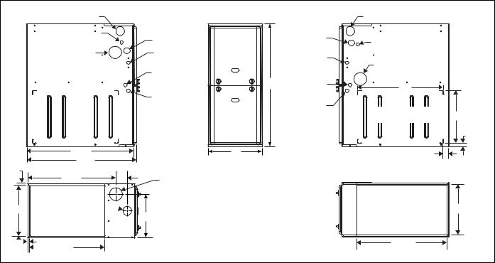
LEFT SIDE |
|
Combustion Air Inlet |
|
Condensate Drain |
Gas Pipe |
(Downflow) |
Entry |
Vent Outlet |
Electrical |
|
Entry |
|
Condensate |
|
Drain |
|
Thermostat |
|
Wiring |
28.5” |
|
29.5” |
|
.56” |
|
23.8” |
3” |
|
Vent |
|
Outlet |
BCombustion 
Air Inlet |
C |
|
.56” |
|
|
|
.56” |
|
|
|
|
|||
|
|
|
|
20” |
|
|
|
|
|
|
|
SUPPLY END
FRONT |
|
RIGHT SIDE |
|
|
Combustion Air Inlet |
|
|
|
|
|
|
|
Gas Pipe |
Condensate Drain |
|
|
Entry |
(Downflow) |
|
|
Electrical |
|
|
|
Entry |
Vent Outlet |
|
33 |
Condensate |
23” |
|
|
Drain |
|
|
|
|
|
|
|
Thermostat |
Optional Return Air |
|
|
Wiring |
14” |
|
|
Cutout (Either side) |
||
|
|
||
|
|
|
|
|
|
|
1” |
A |
|
1.5” |
|
|
|
|
|
|
|
|
B |
|
|
24.25” |
|
RETURN END
Cabinet & Duct Dimensions
|
Nominal |
Cabinet |
Cabinet Dimensions (Inches) |
Approximate |
|||
Model |
Operating Weights |
||||||
CFM (m3/min) |
Size |
|
|
|
|||
|
A |
B |
C |
Lbs |
|||
|
|
|
|||||
|
|
|
|
|
|
|
|
TM9V060B12MP11 |
1200 |
B |
17 1/2 |
16 3/8 |
13 1/4 |
122 |
|
|
|
|
|
|
|
|
|
TM9V080B12MP11 |
1200 |
B |
17 1/2 |
16 3/8 |
13 1/4 |
126 |
|
|
|
|
|
|
|
|
|
TM9V080C16MP11 |
1600 |
C |
21 |
19 7/8 |
16 1/2 |
136 |
|
|
|
|
|
|
|
|
|
TM9V100C16MP11 |
1600 |
C |
21 |
19 7/8 |
18 1/4 |
142 |
|
|
|
|
|
|
|
|
|
TM9V100C20MP11 |
2000 |
C |
21 |
19 7/8 |
18 1/4 |
145 |
|
|
|
|
|
|
|
|
|
TM9V120D20MP11 |
2000 |
D |
24 1/2 |
23 3/8 |
21 3/4 |
156 |
|
|
|
|
|
|
|
|
|
Ratings & Physical / Electrical Data
|
Input |
Output |
|
Total |
AFUE |
High Fire |
Low Fire |
Model |
High/Low |
High/Low |
|
Unit |
Air Temp. Rise |
Air Temp. Rise |
|
|
|
||||||
|
MBH |
MBH |
|
Amps |
% |
°F |
°F |
|
|
|
|
|
|
|
|
TM9V060B12MP11 |
60/39 |
58/37 |
|
9 |
96 |
35 - 65 |
35 - 65 |
|
|
|
|
|
|
|
|
TM9V080B12MP11 |
80/52 |
77/50 |
|
9 |
96 |
35 - 65 |
30 - 60 |
|
|
|
|
|
|
|
|
TM9V080C16MP11 |
80/52 |
77/50 |
|
12 |
96 |
35 - 65 |
35 - 65 |
|
|
|
|
|
|
|
|
TM9V100C16MP11 |
100/65 |
96/62 |
|
12 |
96 |
35 - 65 |
30 - 65 |
|
|
|
|
|
|
|
|
TM9V100C20MP11 |
100/65 |
96/62 |
|
14 |
96 |
35 - 65 |
35 - 65 |
|
|
|
|
|
|
|
|
TM9V120D20MP11 |
120/78 |
115/75 |
|
14 |
96 |
35 - 65 |
35 - 65 |
|
|
|
|
|
|
|
|
|
Max. Outlet |
|
Blower |
Blower Size |
Max. |
Min. Wire Size |
|
Model |
Air Temp. |
|
Over-current |
(awg) @ 75 ft. |
|||
|
|
|
|
||||
|
|
|
|
|
|
Protect |
One Way |
|
°F |
HP |
|
Amps |
In. |
||
|
|
|
|
|
|
|
|
TM9V060B12MP11 |
170 |
1/2 |
|
7 |
11 x 8 |
15 |
14 |
TM9V080B12MP11 |
175 |
1/2 |
|
7 |
11 x 8 |
15 |
14 |
TM9V080C16MP11 |
175 |
3/4 |
|
10.2 |
11 x 10 |
15 |
14 |
TM9V100C16MP11 |
175 |
3/4 |
|
10.2 |
11 x 10 |
15 |
14 |
TM9V100C20MP11 |
175 |
1 |
|
12.7 |
11 x 11 |
20 |
12 |
TM9V120D20MP11 |
170 |
1 |
|
12.7 |
11 x 11 |
20 |
12 |
Annual Fuel Utilization Efficiency (AFUE) numbers are determined in accordance with DOE Test procedures.
Wire size and over current protection must comply with the National Electrical Code (NFPA-70-latest edition) and all local codes. The furnace shall be installed so that the electrical components are protected from water.
2 |
Johnson Controls Unitary Products |
 Loading...