


 Loading...
TECHNICAL GUIDE SUNLINE PLUS™ AIR-COOLED
AIR CONDITIONERS
D1EG/D1EE036, 048, & 060
3, 4, AND 5 NOMINAL TONS
11 - 11.5 SEER
036-21411-002-A-0204
J
FLEXIBLE EASY TO INSTALL SINGLE
PACKAGE UNITS.
GENERAL
YORK Model DEE/DEG units are single package air conditioners designed for outdoor installation on a rooftop or a slab. These units can be equipped with field installed electric heaters for cooling/heating applications or factory installed gas heat. The units are completely assembled on rigid, permanently attached base rails. All piping, refrigerant charge, and electrical wiring is factory installed and tested. The units require only electric power and duct connections at the point of installation.
FEATURING
•COMMON FOOTPRINT / COMMON CABINET
•HIGH EFFICIENCY
•CONVERTIBLE AIRFLOW DESIGN
•OPTIONAL MOTORIZED AIR DAMPER
•OPTIONAL MANUAL OUTDOOR DAMPER
•FLEXIBLE INDOOR AIRFLOWS
•FULL PERIMETER BASE RAILS
•INSTALLER FRIENDLY CONTROL CIRCUIT
•EASY UTILITY CONNECTIONS
•1” OR 2” FILTERS WITH NO MODIFICATIONS
•DIRECT DRIVE
•OPTIONAL BELT DRIVE
•1 YEAR LIMITED WARRANTY
•COMPRESSORS 5 YEAR WARRANTY
•10 YEAR LIMITED WARRANTY ON GAS-FIRED HEAT EXCHANGERS
FOR DISTRIBUTION USE ONLY - NOT TO BE USED AT POINT OF RETAIL SALE
036-21411-002-A-0204
TABLE OF CONTENTS
DESCRIPTION . . . . . . . . . . . . . . . . . . . . . . . . . . . . . . 3 FEATURES . . . . . . . . . . . . . . . . . . . . . . . . . . . . . . . . 3 FACTORY-INSTALLED OPTIONS . . . . . . . . . . . . . . 4 FIELD-INSTALLED ACCESSORIES. . . . . . . . . . . . . 4 MECHANICAL SPECIFICATIONS . . . . . . . . . . . . . 30
|
LIST OF FIGURES |
|
Fig. |
Pg. |
|
1 |
SUNLINE PLUS COMPONENT LOCATION. . . . . . . . |
. . 5 |
2 |
POWER SUPPLY, POWER WIRING THREE PHASE 22 |
|
3 |
CONTROL WIRING - COOLING ONLY . . . . . . . . . . . . |
22 |
4 |
CONTROL WIRINGCOOLING & HEATING |
|
|
MULTI-STAGE . . . . . . . . . . . . . . . . . . . . . . . . . . . . . . . |
22 |
5 |
POWER SUPPLY, POWER WIRING SINGLE |
|
|
PHASE . . . . . . . . . . . . . . . . . . . . . . . . . . . . . . . . . . . . . |
22 |
6 |
CONTROL WIRING - COOLING/HEATING |
|
|
(24 VOLT THERMOSTAT) . . . . . . . . . . . . . . . . . . . . . . |
22 |
7 |
CONTROL WIRING - COOLING/HEATING |
|
|
(ELECTRONIC THERMOSTAT) . . . . . . . . . . . . . . . . . . |
23 |
8 |
UNIT DIMENSIONS WITH ECONOMIZER |
|
|
RAINHOOD . . . . . . . . . . . . . . . . . . . . . . . . . . . . . . . . . . |
23 |
9 |
UNIT DIMENSIONS DEE 3, 4, & 5 TON. . . . . . . . . . . . |
24 |
10 |
ACCESS PANELS AND DISCONNECT . . . . . . . . . . . . |
24 |
11 |
UNIT DIMENSIONS DEG 3, 4, & 5 TON . . . . . . . . . . . |
25 |
12 |
DEE/DEG DIMENSIONS REAR VIEW - |
|
|
3, 4, & 5 TON . . . . . . . . . . . . . . . . . . . . . . . . . . . . . . . . |
26 |
13 |
DETAIL B UNIT DIMENSIONS WITH DAMPER/ |
|
|
RAINHOOD . . . . . . . . . . . . . . . . . . . . . . . . . . . . . . . . . . |
27 |
14 |
UNIT & CURB APPLICATION. . . . . . . . . . . . . . . . . . . . |
27 |
15 |
ROOF CURB DIMENSIONS DEE & DEG |
|
|
3, 4, & 5 TON . . . . . . . . . . . . . . . . . . . . . . . . . . . . . . . . |
28 |
16 |
CENTER OF GRAVITY. . . . . . . . . . . . . . . . . . . . . . . . . |
28 |
17 |
TYPICAL APPLICATIONS . . . . . . . . . . . . . . . . . . . . . . |
29 |
18 |
TYPICAL ROOF TOP INSTALLATION . . . . . . . . . . . . . |
29 |
|
LIST OF TABLES |
|
Tbl. |
Pg. |
|
1 CAPACITY RATINGS - COOLING / ELECTRIC HEATING . . . . . . . . . . . . . . . . . . . . . . . . . . . . . . . . . . . . 7
2 CAPACITY RATINGS - COOLING / GAS HEATING . . . 7
3 SOUND POWER RATINGS . . . . . . . . . . . . . . . . . . . . . . 7 4 PHYSICAL DATA - BASIC UNIT . . . . . . . . . . . . . . . . . . 8 5 COOLING CAPACITIES - 3 TON (DEE / DEG036) . . . . 9 6 COOLING CAPACITIES - 4 TON (DEE / DEG048) . . . 10 7 COOLING CAPACITIES - 5 TON (DEE / DEG060) . . . 11
8 SUPPLY AIR BLOWER PERFORMANCE -DEE/ DEG036 W/ BELT DRIVE & SIDE DUCT . . . . . . . . . . 12
9 SUPPLY AIR BLOWER PERFORMANCE -DEE/ DEG048 W/ BELT DRIVE & SIDE DUCT . . . . . . . . . . 13
10 SUPPLY AIR BLOWER PERFORMANCE -DEE/ DEG060 W/ BELT DRIVE & SIDE DUCT . . . . . . . . . . 14
11 SUPPLY AIR BLOWER PERFORMANCE - DEE/ DEG036-060 W/ DIRECT DRIVE . . . . . . . . . . . . . . . . . 15
12 STATIC RESISTANCES. . . . . . . . . . . . . . . . . . . . . . . . 15
13MOTOR AND DRIVE DATA - BELT-DRIVE BLOWER 16
14BASIC UNIT W/ DIRECT-DRIVE ELECTRICAL DATA 16
15 |
BASIC UNIT W/ BELT-DRIVE ELECTRICAL DATA . . |
17 |
16 |
ELECTRICAL DATA COOLING/ELECTRIC HEAT |
|
|
W/ DIRECT DRIVE DEE036. . . . . . . . . . . . . . . . . . . . . |
18 |
17 |
ELECTRICAL DATA COOLING/ELECTRIC HEAT |
|
|
W/ DIRECT DRIVE DEE048. . . . . . . . . . . . . . . . . . . . . |
19 |
18 |
ELECTRIC HEAT CORRECTION FACTORS . . . . . . . |
19 |
19 |
FUSE BLOCK ACCESSORY . . . . . . . . . . . . . . . . . . . . |
19 |
20 |
ELECTRICAL DATA COOLING/ELECTRIC HEAT |
|
|
W/ DIRECT DRIVE DEE060. . . . . . . . . . . . . . . . . . . . . |
20 |
21 |
ELECTRICAL DATA COOLING/ELECTRIC HEAT |
|
|
W/ BELT DRIVE DEE036 & 048. . . . . . . . . . . . . . . . . . |
21 |
22 |
ELECTRICAL DATA COOLING/ELECTRIC HEAT |
|
|
W/ BELT DRIVE DEE060 . . . . . . . . . . . . . . . . . . . . . . . |
22 |
23 |
UTILITIES ENTRY DATA . . . . . . . . . . . . . . . . . . . . . . . |
25 |
24 |
DEE/DEG UNIT CLEARANCES . . . . . . . . . . . . . . . . . . |
26 |
25 |
ACCESSORY’S WEIGHT. . . . . . . . . . . . . . . . . . . . . . . |
29 |
26 |
UNIT WEIGHTS . . . . . . . . . . . . . . . . . . . . . . . . . . . . . . |
29 |
2 |
Unitary Products Group |
036-21411-002-A-0204
DESCRIPTION
YORK Sunline Plus™ units are high efficiency, convertible, single package air conditioners with a common cabinet and a common roof curb for the 3, 4 and 5 ton sizes. The units were designed for light commercial and commercial applications. They can easily be installed on a roof curb, slab, roof jack or frame.
All units are self--contained and assembled on rigid full perimeter base rails with fork lift slots on three sides and holes for overhead rigging. Every unit is completely piped, wired, charged and tested at the factory to provide for a quick and easy field installation.
The units are available in cooling only, and cooling with gas heat. Electric heaters are available as field--installed accessories.
Both bottom and side duct connections are available without having to swap panels. The installer simply removes the duct covers for the desired configuration. Economizers may be used on either bottom and side duct applications with no modifications required.
All models include a 5--year limited warranty on compressors, a 10--year limited warranty on gas--fired heat exchangers and a 1--year limited warranty on other parts.
FEATURES
COMMON FOOTPRINT/COMMON CABINET -- All model sizes and configurations share a common cabinet and a common roof curb. The installer has the flexibility of setting one curb and placing the proper tonnage unit on that curb after the internal load has been determined. He can even decide between gas or electric heat after the curb has been set.
HIGH EFFICIENCY -- All units have a high cooling efficiency of at least 11.0 SEER and gas / electric models have an AFUE as high as 80.9%. All efficiencies exceed legislated minimum levels and provide low operating costs.
CONVERTIBLE AIRFLOW DESIGN -- Both the side and bottom duct openings are covered when they leave the factory. If a side supply / side return is desired, you simply remove the two side duct covers from the outside of the unit and discard them. If a bottom supply / bottom return is desired, you simply remove the two knockout panels from the base of the unit and discard them. No panel cutting or swapping is required! Convertible airflow design allows maximum field flexibility and minimum inventory.
FACTORY--INSTALLED OPTIONS -- Economizers can be installed at the factory. The economizers are shipped installed and wired. Only the rain hood needs to be field assembled and installed. Field labor dollars can be saved by having the components arrive already installed.
Adjustable belt drive blowers are available on all models from the factory for complete airflow flexibility.
FIELD--INSTALLED ACCESSORIES -- Accessories were designed for quick and easy installation. The motorized damper and economizers simply slide in, and electrical connections are made by modular plugs. Electric heaters mount easily, and knockouts are provided in the internal partitions to connect the elements to the control box single point kit.
The motorized air damper includes a slid--in/plug--in damper assembly with a rainhood and filters. The outdoor air dampers open when the indoor fan motor is energized. The damper is capable of providing 0% through 100% of outdoor return air opening.
The manual outdoor damper provides 0% through 35% or 0% through 100% of return air opening (field adjustable). Designed for duct mounted side or bottom supply/return applications. Includes rain hood assembly and filter.
The 14" high roof curb is shipped knocked down. An insulated deck is not required because the bottom of the unit is insulated.
Low ambient controls are available to provide stable unit operation at outdoor temperatures down to 0 ºF.
Propane, high altitude and low NOx kits are also available to cover all gas heating applications.
WIDE RANGE OF INDOOR AIRFLOWS -- All models operate over a wide range of design conditions with a 3--speed direct--drive fan motor. Belt--drive blowers are also available on all models.
FULL PERIMETER BASE RAILS -- The permanently attached base rails provide a solid foundation for the entire unit and protect the unit during shipment. The rails provide fork lift access from 3 sides, and rigging holes are also provided so that an overhead crane can be used to place the units on a roof.
SYSTEM PROTECTION -- Internal overload protection is standard on all compressors. Every unit has a liquid line filter- -drier, high and low pressure/loss of charge switches and a suction line freezestat to protect all system components. All units will provide cooling at ambient temperatures down to 45 ºF.
UTILITY CONNECTIONS MADE EASY -- Gas and electric utility knockouts are provided in the unit base as well as the side of the unit. A clearly identified location is provided to mount a field supplied electrical disconnect switch. Utility connections can be made quickly and with a minimum amount of field labor.
SIMPLE CONTROL CIRCUIT -- A low voltage printed circuit board contains a compressor lockout indicator light and a low
Unitary Products Group |
3 |
voltage terminal strip. An additional set of pin connectors is also provided to simplify the field interface of external controls. Mate--n--lock plug connectors are used where line and low voltage wires pass through internal bulkheads. This allows for easier troubleshooting and component replacement. The electrical control box is not located in the compressor compartment so the access cover can be removed for troubleshooting without affecting the normal system operating pressures.
AIR FILTERS -- Units are shipped with 1" throwaway filters. The unit filter racks can accommodate 1" or 2" filters without any modifications.
FACTORY-INSTALLED OPTIONS
ECONOMIZERS: Units equipped with a factory-installed economizer option have dampers that are positioned by a spring return, fully modulating damper actuator and are capable of introducing up to 100% outdoor air. As the outdoor air intake dampers open, the return air dampers close. The changeover from mechanical refrigeration to economizer operation is determined by a single input electronic enthalpy control or by a dual input electronic enthalpy control. Simultaneous compressor and economizer operation is also possible.
The single enthalpy system contains a sensor that monitors the outdoor air which automatically operates the damper actuator allowing the dampers to open or close.
The dual enthalpy system contains a second sensor that monitors both the temperature and the humidity of the return air in addition to the outdoor air sensor described for a single enthalpy system. The logic module compares the inputs from both sensors and switches to economizer operation whenever the outdoor air is cooler than the return air for maximum efficiency of the economizer system.
The economizer is completely wired and installed at the factory. Only the outdoor air hood, including its filters, need be assembled and installed in the field.
BELT DRIVE BLOWERS: Adjustable belt-drive blowers providing maximum flexibility to handle many airflow requirements, are available on all models.
FIELD-INSTALLED ACCESSORIES
SINGLE INPUT ELECTRONIC ENTHALPY ECONOMIZER - Includes a slide-in / plug-in damper assembly with fully modulating spring return motor actuator capable of introducing up to 100% outdoor air, one outdoor air electronic enthalpy sensor and a rain hood with filters. The rain hood is painted to match the basic unit and must be field-assembled before installation. Economizer dampers are 2% low leakage type.
036-21411-002-A-0204
DUAL INPUT ELECTRONIC ENTHALPY ECONOMIZER - Includes the same damper system and rain hood with filters as described for a single enthalpy economizer except this accessory contains two enthalpy sensors. It uses a differential enthalpy control that compares the outdoor air versus the return air. The logic module then optimizes the economizer operation for additional savings over the single input economizer.
MOTORIZED AIR DAMPER - Includes a slid-in/plug-in damper assembly with a rainhood and filters. The outdoor air dampers open when the indoor fan motor is energized. The damper is capable of providing 0% through 100% of outdoor return air opening.
MANUAL OUTDOOR DAMPER - Provides 0% through 35% or 0% through 100% of return air opening (field adjustable). Designed for duct mounted side or bottom supply/return applications. Includes rain hood assembly and filter.
ELECTRIC HEATERS - Include nickel chromium elements, a terminal block, fuses (where required by UL), all the necessary connectors and hardware. All heaters utilize single point power supply hookup. Capacities from 5 KW through 30 KW heating are available.
FUSE BLOCK KITS - These kits have a fuse box with a fuse block and fuses. They're available for all 460-3-60 volt heaters and 208/230-3-60 volt heaters 7 KW and smaller.
OUTDOOR THERMOSTAT - A 24-volt thermostat providing two stages of control for units equipped with electric heat accessories.
ROOF CURB - This 14" high full perimeter roof curb is shipped knocked down for field assembly and contains duct supports that can easily be shifted for the desired unit duct arrangement. No insulated deck is required because the unit underside is insulated.
START ASSIST KIT - Provides increased starting torque for single phase units in areas with low voltage conditions. It contains a 12.5 OHM PTCR temperature resistor with a support clip and hardware for mounting.
LOW AMBIENT KIT - A head pressure controller maintains stable system operation by reducing the speed of the condenser fan motor when the outdoor temperature is between 45 and 0 ºF. Condenser fan motors with ball bearings and heavier windings are also available for these low ambient applications.
ANTI-RECYCLE TIMER - A timer to prevent the unit compressor from short cycling. It assures a 5-minute off-time between compressor cycles.
4 |
Unitary Products Group |
036-21411-002-A-0204
PROPANE CONVERSION KIT - Converts a gas-fired heater from natural gas to propane. It contains main burner orifices, a pilot orifice and a regulator spring.
LOW NOx KIT (natural gas furnaces only) - Contains five stainless steel expanded metal sheets for mounting into the heat exchanger tubes to meet the California low nitrous oxide emission requirements.
HIGH ALTITUDE CONVERSION (NATURAL AND PROPANE) - Provides orifices for proper furnace operation at altitudes up to 6000 feet. For propane applications, the propane conversion kit will also be required.
GAS PIPING - This kit contains 1/2" pipe nipples, fittings and gas cock (including panel access gaskets) required for bottom gas supply connection with external shut-off.
OUTDOOR COIL GUARD - Consists of grille-type sections for installation over the outdoor coil to protect it from damage.
WALL THERMOSTAT - The units are designed to operate with 24-volt electronic and electro-mechanical thermostats. All units can operate with single stage heat / single stage cool thermostats - with or without the economizer.
|
|
LONGLASTING |
|
|
|
POWDERPAINTFINISH |
|
LOWVOLTAGERELAYBOARD |
20GAUGEALUMINIZEDSTEEL |
|
|
ANDTERMINALSTRIP |
|
TUBULARHEATEXCHANGER |
ELECTRICHEATACCESSORY |
|
DIRECTDRIVEBLOWER |
LOCATION(Elec/ElecUnits) |
|
|
|
||
|
MOTOR(BeltDriveOption |
POWERVENTERMOTOR |
|
ELECTRICALDISCONNECT |
alsoavailableonsome |
||
models) |
|
WITHPOSTPURGECYCLE |
|
MOUNTINGLOCATION |
|
||
|
|
|
|
(FieldInstaled) |
|
|
COPPERTUBE/ |
|
|
|
ALUMINUMFIN |
|
|
|
CONDENSERCOIL |
ECONOMIZERHOOD
OUTDOORAIROPENING
FORSLIDE-IN/PLUGIN
INTERNALECONOMIZER
SIDERETURNAIR
DUCTOPENING
BOTTOMRETURNAIR
DUCTOPENING
3/4"PVCFEMALE CONDENSATEDRAIN
KNOCKOUTSFORSIDE
POWERANDCONTROL
ENTRY
HIGHEFFICIENCY
COMPRESSORS
|
|
|
FULLPERIMETERBASERAILS |
|
|
|
|
WITHFORKLIFTSLOTSAND |
|
|
|
|
LIFTINGHOLES |
|
|
|
KNOCKOUTFORSIDE |
||
|
|
GASSUPPLYENTRY |
||
|
KNOCKOUTFORBOTTOM |
|||
|
GASSUPPLYENTRY |
|
|
|
TERMINALBLOCK |
|
MODELDEG |
|
|
KNOCKOUTFORBOTTOM |
|
|
||
|
|
|
||
(ForSinglePointPower |
|
(GasHeating) |
|
|
POWERENTRY |
|
|
||
SupplyonElec/ElecUnits) |
|
|
|
|
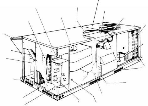
FIGURE 1 - SUNLINE PLUS COMPONENT LOCATION
Unitary Products Group |
5 |

036-21411-002-A-0204
TABLE 1: CAPACITY RATINGS - COOLING / ELECTRIC HEATING
|
|
|
ARI RATINGS1 |
|
|
|
NOMINAL ELECTRIC HEAT CAPACITY2 (kW) |
|||
MODEL |
|
COOLING CAPACITY 80 / 67-95°F |
|
SOUND |
||||||
|
|
|
|
|
||||||
|
MBH |
|
SEER4 |
|
EER5 |
RATING3 |
|
240V |
480V |
600V |
|
|
|
(dBels) |
|||||||
|
|
|
|
|
|
|
|
|
||
DEE036 |
42.5 |
|
11.5 |
|
10.10 |
86.0 |
|
5, 7, 10, 15 & |
7, 10, 15 & 20 |
10, 15, & 20 |
|
|
|
20 |
|||||||
|
|
|
|
|
|
|
|
|
|
|
DEE048 |
49.5 |
|
11.0 |
|
10.0 |
86.0 |
|
5, 7, 10, 15 & |
7, 10, 15 & 20 |
10, 15, & 20 |
|
|
|
20 |
|||||||
|
|
|
|
|
|
|
|
|
|
|
DEE060 |
58.5 |
|
11.0 |
|
10.05 |
86.0 |
|
5, 7, 10, 15, |
7, 10, 15, 10, |
10, 15, 20 & |
|
|
|
20, & 30 |
& 30 |
30 |
|||||
|
|
|
|
|
|
|
|
|||
1. Certified in accordance with the Unitary Small Equipment certification program, which is based on ARI Standard 210/240.
2. Heaters are available as accessories - all with single point power supply |
Not ARI required |
3.Rated in accordance with ARI Standard 270.
4.SEER =Seasonal Energy Efficiency Ratio - the total cooling output in BTU’s during a normal annual usage period for cooling divided by the total electric power input in watt-hours during the same period.
5.EER = Energy Efficiency Ratio - the cooling capacity in BTU’s per hour (BTUH) divided by the power input in watts at any given set of rating conditions, expressed in BTUH per watt (BTUH/watt).
TABLE 2: CAPACITY RATINGS - COOLING / GAS HEATING
|
|
ARI RATINGS1 |
|
|
|
GAS HEAT CAPACITY |
|
|
|||
MODEL |
COOLING CAPACITY 80 / |
SOUND |
INPUT |
OUTPUT |
|
|
|
TEMP. |
GASE LINE SIZE |
||
|
67-95°F |
|
RATING2 |
AFUE3 (%) |
S.S.E.4 (%) |
|
RISE |
||||
|
|
|
(MBH) |
(MBH) |
|
(in. O.D.) |
|||||
|
MBH |
SEER5 |
EER6 |
(dBels) |
|
|
|
(°F) |
|||
|
|
|
|
|
|
|
|||||
DEG036N040 |
42.5 |
11.5 |
10.1 |
86 |
50 |
40 |
80.9 |
81.6 |
|
15-45 |
1/2 |
DEG036N079 |
42.5 |
11.5 |
10.1 |
86 |
100 |
79 |
80.5 |
80.8 |
|
40-70 |
1/2 |
DEG048N060 |
49.5 |
11.0 |
10.0 |
86 |
75 |
59 |
80.9 |
81.6 |
|
25-55 |
1/2 |
DEG048N099 |
49.5 |
11.0 |
|
|
|
|
|
|
|
|
|
10.0 |
86 |
125 |
99 |
80.3 |
80.6 |
|
45-75 |
1/2 |
|||
DEG060N079 |
58.5 |
11.0 |
10.05 |
86 |
100 |
79 |
80.5 |
80.8 |
|
25-55 |
1/2 |
|
|
|
|
|
|
|
|
|
|
|
|
DEG060N099 |
58.5 |
11.0 |
10.05 |
86 |
125 |
99 |
80.3 |
80.6 |
|
35-65 |
1/2 |
1. |
Ratings are in accordance with ARI Standard 210. |
|
Not ARI required |
2. |
Sound ratings are in accordance with ARI Standard 270. |
|
|
|
|
|
3.AFUE = Annual Fuel Utilization Efficiency - determined in accordance with DOE test procedure.
4.S.S.E. = Steady State Efficiency (Percent Output).
5.SEER =Seasonal Energy Efficiency Ratio - the total cooling output in BTU’s during a normal annual usage period for cooling divided by the total electric power input in watt-hours during the same period.
6.EER = Energy Efficiency Ratio - the cooling capacity in BTU’s per hour (BTUH) divided by the power input in watts at any given set of rating conditions, expressed in BTUH per watt (BTUH/watt).
TABLE 3: SOUND POWER RATINGS1
UNIT |
|
ESP |
BLOWER |
|
|
|
|
SOUND POWER (dB 10-12 WATTS) |
|
|
|||||
SIZE |
CFM |
|
|
|
|
OCTAVE BAND CENTERLINE FREQUENCY (Hz) |
|
SWL |
dBA |
||||||
|
|
|
|
|
|
|
|
|
|
|
|
|
dB(A) |
@ 10Ft2 |
|
|
|
IWG |
SPEED |
kW |
63 |
125 |
250 |
500 |
|
1000 |
2000 |
4000 |
8000 |
||
036 |
1200 |
0.60 |
LOW |
0.60 |
84 |
84 |
74 |
67 |
|
69 |
62 |
57 |
52 |
74 |
41 |
048 |
1600 |
0.55 |
HIGH |
0.80 |
85 |
85 |
75 |
68 |
|
70 |
63 |
58 |
53 |
75 |
42 |
|
|
|
|
|
|
|
|
|
|
|
|
|
|
|
|
060 |
2000 |
0.45 |
HIGH |
1.00 |
86 |
86 |
76 |
69 |
|
71 |
64 |
59 |
54 |
76 |
43 |
1.These values have been accessed using a model of sound propagation from a point source into the hemispheric free field. The dBA values provided are to be used fro reference only. Calculation of dBA values cover matters of system design and the fan manufacture has no way of knowing the details of each system. This constitutes an exception to any specification or guarantee requiring a dBA value or sound data in any other form than sound power level ratings.
2.At a distance of 10 feet from the blower.
6 |
Unitary Products Group |
036-21411-002-A-0204
TABLE 4: PHYSICAL DATA - BASIC UNIT
|
MODELS |
|
DEE/DEG |
|
|
|
|
036 |
048 |
060 |
|
EVAPORATOR |
Centrifugal Blower (Dia. x Wd. in.) |
12 x 10 |
12 x 10 |
12 x 10 |
|
Fan Motor HP (Direct - Drive) |
1/2 |
3/4 |
1 |
||
BLOWER |
|||||
Fan Motor HP (Belt - Drive) |
1.5 |
1.5 |
1.5 |
||
|
|||||
|
|
|
|
|
|
EVAPORATOR |
Rows Deep |
3 |
3 |
3 |
|
Fins Per Inch |
13 |
13 |
13 |
||
COIL |
|||||
Face Area (Sq. Ft.) |
3.6 |
4.3 |
5.1 |
||
|
|||||
|
|
|
|
|
|
CONDENSER |
Propeller Dia. (in.) |
22 |
22 |
22 |
|
Fan Motor HP |
1/2 |
1/2 |
1/2 |
||
FAN |
|||||
Nom. CFM. Total |
4,500 |
4,200 |
4,500 |
||
|
|||||
|
|
|
|
|
|
CONDENSER |
Rows Deep |
2 |
2 |
2 |
|
Fins Per Inch |
18 |
18 |
18 |
||
COIL |
|||||
Face Area (Sq. Ft.) |
17.1 |
17.1 |
17.1 |
||
|
|||||
|
|
|
|
|
|
AIR FILTERS1 |
Quantity Per Unit (15” x 20” x 1”) |
2 |
2 |
2 |
|
Quantity Per Unit (14” x 25” x 1”) |
1 |
1 |
1 |
||
|
Total Face ARea (Sq. Ft.) |
6.6 |
6.6 |
6.6 |
|
|
|
|
|
|
|
SYSTEM CHARGE |
Refrigerant 22 (Lbs./Oz.) |
9/12 |
9/8 |
9/8 |
|
|
|
|
|
|
|
COMPRESSOR |
Quantity Per Unit: (Hermetic Type) |
1 / Recpt |
1 / Recpt |
1 / Scroll |
1. Filter racks are adapted for 1” or 2” thick filters.
Unitary Products Group |
7 |

|
|
|
|
|
|
|
|
|
|
|
|
|
|
|
|
|
|
|
036-21411-002-A-0204 |
||||
TABLE 5: COOLING CAPACITIES - 3 TON (DEE / DEG036) |
|
|
|
|
|
|
|
|
|
|
|
||||||||||||
|
|
|
|
|
|
|
|
|
|
|
|
|
|
|
|
|
|
|
|
|
|
|
|
AIR ON |
|
|
|
|
|
|
TEMPERATURE OF AIR ON CONDENSER COIL |
|
|
|
|
|
|
|
|
||||||||
|
|
|
85°F |
|
|
|
|
|
|
|
|
|
95°F |
|
|
|
|
|
|||||
EVAPORATOR |
|
|
|
SENSIBLE CAPACITY1, MBH |
|
|
|
|
|
SENSIBLE CAPACITY1, MBH |
|
||||||||||||
COIL |
|
TOTAL |
POWER |
|
|
TOTAL |
POWER |
|
|
|
|||||||||||||
|
|
|
|
ENTERING DRY BULB, °F |
|
|
|
ENTERING DRY BULB, °F |
|
||||||||||||||
|
|
|
CAP.1 |
INPUT2 |
|
|
CAP.1 |
INPUT2 |
|
|
|
||||||||||||
CFM |
|
WB |
MBH |
kW |
86 |
83 |
|
80 |
77 |
74 |
71 |
68 |
MBH |
kW. |
|
86 |
83 |
|
80 |
77 |
74 |
71 |
68 |
|
|
°F |
|
|
|
|
|
|
|
|
|
|
|
|
|
|
|
|
|
|
|
|
|
|
|
72 |
55 |
3.4 |
35 |
31 |
|
26 |
22 |
18 |
- |
- |
51 |
3.7 |
|
35 |
30 |
|
26 |
21 |
17 |
- |
- |
1500 |
|
67 |
52 |
3.3 |
47 |
42 |
|
38 |
33 |
29 |
24 |
20 |
48 |
3.6 |
|
45 |
41 |
|
36 |
32 |
28 |
23 |
19 |
|
|
|
|
|
|
|
|
|
|
|
|
|
|
|
|
|
|
|
|
|
|
|
|
|
|
62 |
42 |
3.2 |
42 |
42 |
|
42 |
37 |
33 |
28 |
24 |
39 |
3.5 |
|
39 |
39 |
|
39 |
34 |
30 |
25 |
21 |
|
|
57 |
42 |
3.2 |
42 |
42 |
|
42 |
38 |
33 |
29 |
24 |
39 |
3.5 |
|
39 |
39 |
|
39 |
35 |
30 |
26 |
21 |
|
|
72 |
51 |
3.3 |
32 |
28 |
|
24 |
20 |
16 |
- |
- |
49 |
3.6 |
|
32 |
28 |
|
24 |
20 |
16 |
- |
- |
|
|
|
|
|
|
|
|
|
|
|
|
|
|
|
|
|
|
|
|
|
|
|
|
1350 |
|
67 |
49 |
3.3 |
42 |
38 |
|
34 |
30 |
26 |
22 |
18 |
47 |
3.5 |
|
42 |
38 |
|
34 |
30 |
26 |
22 |
18 |
|
|
|
|
|
|
|
|
|
|
|
|
|
|
|
|
|
|
|
|
|
|
|
|
|
|
62 |
39 |
3.2 |
39 |
39 |
|
37 |
33 |
29 |
25 |
21 |
37 |
3.5 |
|
37 |
37 |
|
37 |
33 |
29 |
25 |
21 |
|
|
57 |
40 |
3.2 |
40 |
40 |
|
38 |
34 |
30 |
26 |
22 |
38 |
3.5 |
|
38 |
38 |
|
38 |
34 |
30 |
26 |
22 |
|
|
72 |
48 |
3.2 |
28 |
24 |
|
21 |
17 |
14 |
- |
- |
48 |
3.6 |
|
29 |
25 |
|
22 |
18 |
15 |
- |
- |
|
|
|
|
|
|
|
|
|
|
|
|
|
|
|
|
|
|
|
|
|
|
|
|
1200 |
|
67 |
46 |
3.3 |
37 |
34 |
|
30 |
27 |
23 |
19 |
16 |
46 |
3.5 |
|
39 |
36 |
|
32 |
38 |
25 |
21 |
18 |
|
|
62 |
36 |
3.2 |
36 |
36 |
|
33 |
29 |
26 |
22 |
19 |
36 |
3.5 |
|
36 |
36 |
|
35 |
31 |
28 |
24 |
21 |
|
|
57 |
37 |
3.2 |
37 |
37 |
|
35 |
31 |
27 |
24 |
20 |
37 |
3.4 |
|
37 |
37 |
|
37 |
33 |
30 |
26 |
22 |
|
|
72 |
46 |
3.3 |
26 |
23 |
|
19 |
16 |
13 |
- |
- |
45 |
3.6 |
|
26 |
23 |
|
20 |
16 |
13 |
- |
- |
1050 |
|
67 |
44 |
3.3 |
34 |
31 |
|
28 |
25 |
22 |
18 |
15 |
43 |
3.5 |
|
35 |
32 |
|
28 |
25 |
22 |
19 |
16 |
|
|
|
|
|
|
|
|
|
|
|
|
|
|
|
|
|
|
|
|
|
|
|
|
|
|
62 |
35 |
3.2 |
35 |
34 |
|
31 |
28 |
24 |
21 |
18 |
34 |
3.4 |
|
34 |
33 |
|
31 |
28 |
25 |
22 |
19 |
|
|
57 |
36 |
3.2 |
36 |
35 |
|
32 |
29 |
26 |
23 |
20 |
35 |
3.4 |
|
35 |
34 |
|
33 |
30 |
27 |
23 |
20 |
|
|
72 |
45 |
3.3 |
24 |
21 |
|
18 |
15 |
13 |
- |
- |
43 |
3.5 |
|
23 |
20 |
|
17 |
15 |
12 |
- |
- |
|
|
|
|
|
|
|
|
|
|
|
|
|
|
|
|
|
|
|
|
|
|
|
|
900 |
|
67 |
42 |
3.2 |
31 |
29 |
|
26 |
23 |
20 |
17 |
15 |
40 |
3.5 |
|
30 |
28 |
|
25 |
22 |
19 |
16 |
14 |
|
|
|
|
|
|
|
|
|
|
|
|
|
|
|
|
|
|
|
|
|
|
|
|
|
|
62 |
34 |
3.2 |
34 |
32 |
|
26 |
26 |
23 |
20 |
18 |
32 |
3.4 |
|
32 |
30 |
|
28 |
25 |
22 |
19 |
17 |
|
|
57 |
35 |
3.1 |
35 |
33 |
|
30 |
27 |
25 |
22 |
19 |
33 |
3.4 |
|
33 |
32 |
|
29 |
26 |
24 |
21 |
18 |
|
|
|
|
|
|
|
|
|
|
|
|
|
|
|
|
|
|
|
|
|
|
|
|
AIR ON |
|
|
|
|
|
|
TEMPERATURE OF AIR ON CONDENSER COIL |
|
|
|
|
|
|
|
|
||||||||
|
|
|
105°F |
|
|
|
|
|
|
|
|
|
115°F |
|
|
|
|
|
|||||
EVAPORATOR |
|
|
|
|
|
|
|
|
|
|
|
|
|
|
|
|
|
|
|
|
|
||
|
|
|
SENSIBLE CAPACITY1, MBH |
|
|
|
|
|
SENSIBLE CAPACITY1, MBH |
|
|||||||||||||
COIL |
|
TOTAL |
POWER |
|
|
TOTAL |
POWER |
|
|
|
|||||||||||||
|
|
|
|
ENTERING DRY BULB, °F |
|
|
|
ENTERING DRY BULB, °F |
|
||||||||||||||
|
|
|
CAP.1 |
INPUT2 |
|
|
CAP.1 |
INPUT2 |
|
|
|
||||||||||||
CFM |
|
WB |
MBH |
kW. |
86 |
83 |
|
80 |
77 |
74 |
71 |
68 |
MBH |
kW. |
|
86 |
83 |
|
80 |
77 |
74 |
71 |
68 |
|
|
°F |
|
|
|
|
|
|
|
|
|
|
|
|
|
|
|
|
|
|
|
|
|
|
|
72 |
47 |
3.9 |
33 |
29 |
|
25 |
20 |
16 |
- |
- |
43 |
4.1 |
|
32 |
28 |
|
23 |
19 |
14 |
- |
- |
1500 |
|
67 |
44 |
3.8 |
43 |
39 |
|
35 |
30 |
26 |
22 |
17 |
40 |
4.1 |
|
40 |
38 |
|
33 |
29 |
24 |
20 |
16 |
|
|
|
|
|
|
|
|
|
|
|
|
|
|
|
|
|
|
|
|
|
|
|
|
|
|
62 |
36 |
3.7 |
36 |
36 |
|
36 |
31 |
27 |
22 |
18 |
33 |
4.0 |
|
33 |
33 |
|
33 |
28 |
24 |
19 |
15 |
|
|
57 |
36 |
3.7 |
36 |
36 |
|
36 |
31 |
27 |
23 |
18 |
33 |
3.9 |
|
33 |
33 |
|
33 |
28 |
24 |
20 |
15 |
|
|
72 |
44 |
3.9 |
30 |
26 |
|
22 |
18 |
14 |
- |
- |
39 |
4.1 |
|
28 |
24 |
|
20 |
16 |
12 |
- |
- |
|
|
|
|
|
|
|
|
|
|
|
|
|
|
|
|
|
|
|
|
|
|
|
|
1350 |
|
67 |
42 |
3.8 |
39 |
36 |
|
32 |
28 |
24 |
20 |
16 |
37 |
4.0 |
|
36 |
33 |
|
29 |
25 |
21 |
17 |
13 |
|
|
|
|
|
|
|
|
|
|
|
|
|
|
|
|
|
|
|
|
|
|
|
|
|
|
62 |
34 |
3.7 |
34 |
34 |
|
33 |
29 |
25 |
21 |
17 |
30 |
4.0 |
|
30 |
30 |
|
30 |
26 |
22 |
18 |
14 |
|
|
57 |
34 |
3.7 |
34 |
34 |
|
34 |
30 |
26 |
22 |
18 |
30 |
3.9 |
|
30 |
30 |
|
31 |
27 |
23 |
19 |
15 |
|
|
72 |
42 |
3.8 |
27 |
23 |
|
20 |
16 |
12 |
- |
- |
36 |
4.1 |
|
24 |
21 |
|
17 |
14 |
10 |
- |
- |
|
|
|
|
|
|
|
|
|
|
|
|
|
|
|
|
|
|
|
|
|
|
|
|
1200 |
|
67 |
40 |
3.8 |
36 |
32 |
|
29 |
25 |
22 |
18 |
14 |
34 |
4.0 |
|
33 |
29 |
|
25 |
22 |
18 |
15 |
11 |
|
|
|
|
|
|
|
|
|
|
|
|
|
|
|
|
|
|
|
|
|
|
|
|
|
|
62 |
32 |
3.7 |
32 |
32 |
|
31 |
28 |
24 |
20 |
17 |
27 |
3.9 |
|
27 |
27 |
|
28 |
24 |
20 |
17 |
13 |
|
|
57 |
32 |
3.7 |
32 |
32 |
|
33 |
29 |
26 |
22 |
19 |
28 |
3.9 |
|
28 |
28 |
|
29 |
26 |
22 |
18 |
15 |
|
|
72 |
40 |
3.8 |
24 |
21 |
|
18 |
15 |
12 |
- |
- |
35 |
4.1 |
|
22 |
19 |
|
16 |
13 |
10 |
- |
- |
|
|
|
|
|
|
|
|
|
|
|
|
|
|
|
|
|
|
|
|
|
|
|
|
1050 |
|
67 |
38 |
3.7 |
32 |
29 |
|
26 |
23 |
19 |
16 |
13 |
33 |
4.0 |
|
30 |
26 |
|
23 |
20 |
17 |
14 |
11 |
|
|
|
|
|
|
|
|
|
|
|
|
|
|
|
|
|
|
|
|
|
|
|
|
|
|
62 |
30 |
3.7 |
30 |
30 |
|
28 |
25 |
22 |
19 |
16 |
27 |
3.9 |
|
27 |
27 |
|
26 |
22 |
19 |
16 |
13 |
|
|
57 |
31 |
3.6 |
31 |
31 |
|
30 |
27 |
24 |
20 |
17 |
27 |
3.9 |
|
27 |
27 |
|
27 |
24 |
21 |
17 |
14 |
|
|
72 |
38 |
3.8 |
22 |
19 |
|
16 |
13 |
11 |
- |
- |
34 |
4.0 |
|
20 |
18 |
|
15 |
12 |
9 |
- |
- |
|
|
|
|
|
|
|
|
|
|
|
|
|
|
|
|
|
|
|
|
|
|
|
|
900 |
|
67 |
36 |
3.7 |
29 |
26 |
|
23 |
20 |
17 |
15 |
12 |
32 |
4.0 |
|
27 |
24 |
|
21 |
18 |
16 |
13 |
10 |
|
|
|
|
|
|
|
|
|
|
|
|
|
|
|
|
|
|
|
|
|
|
|
|
|
|
62 |
29 |
3.6 |
29 |
28 |
|
26 |
23 |
20 |
17 |
15 |
26 |
3.9 |
|
26 |
26 |
|
24 |
21 |
18 |
15 |
13 |
|
|
57 |
30 |
3.6 |
30 |
29 |
|
27 |
24 |
21 |
19 |
16 |
26 |
3.9 |
|
26 |
26 |
|
25 |
22 |
19 |
17 |
14 |
1.These capacities are gross ratings. For net capacity, determine the kW of the supply air blower motor from Table 8 or 11, multiply this value by 3.425 MBH/kW to determine the motor heat, and deduct this heat from the gross capacity of the unit.
2.These ratings include the compressor and the condenser fan motors but not the supply air blower motor. The total condenser fan motor power input is 0.36kW. Refer to Table 8 or 11 for the kW of the supply air blower motor.
|
NOMINAL RATING |
|
ALL SENSIBLE CAPACITY |
|
|
||
|
|
|
|
8 |
Unitary Products Group |

036-21411-002-A-0204
TABLE 6: COOLING CAPACITIES - 4 TON (DEE / DEG048)
AIR ON |
|
|
|
|
|
|
TEMPERATURE OF AIR ON CONDENSER COIL |
|
|
|
|
|
|
|
|
||||||||
|
|
|
85°F |
|
|
|
|
|
|
|
|
|
95°F |
|
|
|
|
|
|||||
EVAPORATOR |
|
|
|
|
|
|
|
|
|
|
|
|
|
|
|
|
|
|
|
|
|
||
|
|
|
SENSIBLE CAPACITY1, MBH |
|
|
|
|
|
SENSIBLE CAPACITY1, MBH |
|
|||||||||||||
COIL |
|
TOTAL |
POWER |
|
|
TOTAL |
POWER |
|
|
|
|||||||||||||
|
|
|
|
ENTERING DRY BULB, °F |
|
|
|
ENTERING DRY BULB, °F |
|
||||||||||||||
|
|
|
CAP.1 |
INPUT2 |
|
|
CAP.1 |
INPUT2 |
|
|
|
||||||||||||
CFM |
|
WB |
MBH |
kW |
86 |
83 |
|
80 |
77 |
74 |
71 |
68 |
MBH |
kW. |
|
86 |
83 |
|
80 |
77 |
74 |
71 |
68 |
|
|
°F |
|
|
|
|
|
|
|
|
|
|
|
|
|
|
|
|
|
|
|
|
|
|
|
72 |
64 |
3.9 |
45 |
39 |
|
33 |
27 |
21 |
- |
- |
60 |
4.2 |
|
44 |
38 |
|
32 |
26 |
20 |
- |
- |
2000 |
|
67 |
57 |
3.8 |
55 |
49 |
|
43 |
37 |
31 |
25 |
19 |
53 |
4.1 |
|
53 |
47 |
|
41 |
35 |
29 |
23 |
17 |
|
62 |
54 |
3.8 |
54 |
54 |
|
53 |
47 |
41 |
35 |
29 |
50 |
4.0 |
|
50 |
50 |
|
50 |
44 |
38 |
32 |
26 |
|
|
|
|
|
|
|||||||||||||||||||
|
|
57 |
54 |
3.8 |
54 |
54 |
|
54 |
48 |
42 |
36 |
30 |
50 |
4.0 |
|
50 |
50 |
|
50 |
46 |
40 |
34 |
28 |
|
|
72 |
62 |
3.9 |
42 |
36 |
|
31 |
25 |
20 |
- |
- |
58 |
4.2 |
|
41 |
35 |
|
30 |
24 |
19 |
- |
- |
|
|
|
|
|
|
|
|
|
|
|
|
|
|
|
|
|
|
|
|
|
|
|
|
1800 |
|
67 |
55 |
3.8 |
51 |
46 |
|
40 |
35 |
30 |
24 |
19 |
52 |
4.1 |
|
50 |
44 |
|
39 |
34 |
28 |
23 |
18 |
|
|
|
|
|
|
|
|
|
|
|
|
|
|
|
|
|
|
|
|
|
|
|
|
|
|
62 |
52 |
3.8 |
52 |
52 |
|
49 |
44 |
39 |
33 |
28 |
49 |
4.1 |
|
49 |
49 |
|
47 |
42 |
37 |
31 |
26 |
|
|
57 |
52 |
3.8 |
52 |
52 |
|
51 |
45 |
40 |
35 |
29 |
49 |
4.1 |
|
49 |
49 |
|
49 |
44 |
38 |
33 |
27 |
|
|
72 |
59 |
3.9 |
38 |
33 |
|
29 |
24 |
19 |
- |
- |
57 |
4.2 |
|
38 |
33 |
|
28 |
23 |
18 |
- |
- |
|
|
|
|
|
|
|
|
|
|
|
|
|
|
|
|
|
|
|
|
|
|
|
|
1600 |
|
67 |
54 |
3.8 |
48 |
43 |
|
38 |
33 |
29 |
24 |
19 |
52 |
4.2 |
|
47 |
42 |
|
37 |
32 |
28 |
23 |
18 |
|
|
62 |
50 |
3.7 |
50 |
50 |
|
46 |
41 |
36 |
32 |
27 |
47 |
4.1 |
|
47 |
47 |
|
45 |
40 |
35 |
31 |
26 |
|
|
57 |
50 |
3.7 |
50 |
50 |
|
47 |
42 |
38 |
33 |
28 |
47 |
4.1 |
|
47 |
47 |
|
46 |
41 |
37 |
32 |
27 |
|
|
72 |
58 |
3.8 |
35 |
31 |
|
27 |
23 |
18 |
- |
- |
55 |
4.2 |
|
34 |
30 |
|
26 |
22 |
17 |
- |
- |
1400 |
|
67 |
52 |
3.8 |
44 |
39 |
|
35 |
31 |
27 |
22 |
18 |
49 |
4.2 |
|
42 |
38 |
|
34 |
30 |
26 |
21 |
17 |
|
|
|
|
|
|
|
|
|
|
|
|
|
|
|
|
|
|
|
|
|
|
|
|
|
|
62 |
49 |
3.7 |
48 |
47 |
|
43 |
39 |
34 |
30 |
26 |
46 |
4.1 |
|
46 |
45 |
|
42 |
37 |
33 |
29 |
25 |
|
|
57 |
49 |
3.7 |
49 |
48 |
|
44 |
40 |
36 |
31 |
27 |
46 |
4.1 |
|
46 |
46 |
|
43 |
38 |
34 |
30 |
26 |
|
|
72 |
57 |
3.8 |
32 |
29 |
|
25 |
21 |
17 |
- |
- |
53 |
4.2 |
|
31 |
28 |
|
24 |
20 |
16 |
- |
- |
|
|
|
|
|
|
|
|
|
|
|
|
|
|
|
|
|
|
|
|
|
|
|
|
1200 |
|
67 |
50 |
3.8 |
40 |
36 |
|
32 |
29 |
25 |
21 |
17 |
47 |
4.2 |
|
38 |
35 |
|
31 |
27 |
23 |
20 |
16 |
|
|
|
|
|
|
|
|
|
|
|
|
|
|
|
|
|
|
|
|
|
|
|
|
|
|
62 |
48 |
3.7 |
47 |
44 |
|
40 |
36 |
33 |
29 |
25 |
45 |
4.1 |
|
45 |
42 |
|
38 |
34 |
31 |
27 |
23 |
|
|
57 |
48 |
3.7 |
48 |
45 |
|
41 |
37 |
34 |
30 |
26 |
45 |
4.1 |
|
45 |
43 |
|
39 |
35 |
32 |
28 |
24 |
|
|
|
|
|
|
|
|
|
|
|
|
|
|
|
|
|
|
|
|
|
|
|
|
AIR ON |
|
|
|
|
|
|
TEMPERATURE OF AIR ON CONDENSER COIL |
|
|
|
|
|
|
|
|
||||||||
|
|
|
105°F |
|
|
|
|
|
|
|
|
|
115°F |
|
|
|
|
|
|||||
EVAPORATOR |
|
|
|
|
|
|
|
|
|
|
|
|
|
|
|
|
|
|
|
|
|
||
|
|
|
SENSIBLE CAPACITY1, MBH |
|
|
|
|
|
SENSIBLE CAPACITY1, MBH |
|
|||||||||||||
COIL |
|
TOTAL |
POWER |
|
|
TOTAL |
POWER |
|
|
|
|||||||||||||
|
|
|
|
ENTERING DRY BULB, °F |
|
|
|
ENTERING DRY BULB, °F |
|
||||||||||||||
|
|
|
CAP.1 |
INPUT2 |
|
|
CAP.1 |
INPUT2 |
|
|
|
||||||||||||
CFM |
|
WB |
MBH |
kW. |
86 |
83 |
|
80 |
77 |
74 |
71 |
68 |
MBH |
kW. |
|
86 |
83 |
|
80 |
77 |
74 |
71 |
68 |
|
|
°F |
|
|
|
|
|
|
|
|
|
|
|
|
|
|
|
|
|
|
|
|
|
|
|
72 |
56 |
4.7 |
42 |
36 |
|
30 |
25 |
19 |
- |
- |
53 |
5.2 |
|
41 |
35 |
|
29 |
23 |
17 |
- |
- |
2000 |
|
67 |
50 |
4.6 |
50 |
45 |
|
39 |
33 |
28 |
22 |
16 |
47 |
5.1 |
|
47 |
44 |
|
38 |
32 |
26 |
20 |
14 |
|
62 |
47 |
4.5 |
47 |
47 |
|
47 |
41 |
35 |
29 |
23 |
44 |
5.0 |
|
44 |
44 |
|
44 |
38 |
32 |
26 |
20 |
|
|
|
|
|
|
|||||||||||||||||||
|
|
57 |
47 |
4.5 |
47 |
47 |
|
47 |
44 |
38 |
32 |
26 |
44 |
5.0 |
|
44 |
44 |
|
44 |
42 |
36 |
30 |
24 |
|
|
72 |
54 |
4.7 |
39 |
34 |
|
29 |
23 |
17 |
- |
- |
51 |
5.1 |
|
38 |
33 |
|
27 |
22 |
17 |
- |
- |
|
|
|
|
|
|
|
|
|
|
|
|
|
|
|
|
|
|
|
|
|
|
|
|
1800 |
|
67 |
49 |
4.6 |
47 |
43 |
|
37 |
32 |
27 |
21 |
16 |
46 |
5.1 |
|
45 |
41 |
|
36 |
31 |
25 |
20 |
14 |
|
|
|
|
|
|
|
|
|
|
|
|
|
|
|
|
|
|
|
|
|
|
|
|
|
|
62 |
46 |
4.5 |
46 |
46 |
|
45 |
40 |
34 |
29 |
23 |
43 |
5.0 |
|
43 |
43 |
|
43 |
37 |
32 |
26 |
21 |
|
|
57 |
46 |
4.5 |
46 |
46 |
|
46 |
42 |
36 |
31 |
26 |
43 |
5.0 |
|
43 |
43 |
|
43 |
40 |
34 |
29 |
24 |
|
|
72 |
53 |
4.7 |
36 |
31 |
|
27 |
22 |
17 |
- |
- |
49 |
5.1 |
|
35 |
30 |
|
25 |
21 |
16 |
- |
- |
|
|
|
|
|
|
|
|
|
|
|
|
|
|
|
|
|
|
|
|
|
|
|
|
1600 |
|
67 |
48 |
4.6 |
45 |
40 |
|
35 |
31 |
26 |
21 |
16 |
44 |
5.1 |
|
43 |
39 |
|
34 |
29 |
24 |
19 |
15 |
|
|
|
|
|
|
|
|
|
|
|
|
|
|
|
|
|
|
|
|
|
|
|
|
|
|
62 |
44 |
4.6 |
44 |
44 |
|
43 |
38 |
33 |
29 |
24 |
41 |
5.0 |
|
41 |
41 |
|
41 |
36 |
31 |
26 |
22 |
|
|
57 |
44 |
4.5 |
44 |
44 |
|
44 |
39 |
34 |
30 |
25 |
41 |
5.0 |
|
41 |
41 |
|
41 |
37 |
32 |
28 |
23 |
|
|
72 |
51 |
4.7 |
33 |
29 |
|
25 |
21 |
16 |
- |
- |
48 |
5.1 |
|
32 |
28 |
|
24 |
20 |
15 |
- |
- |
|
|
|
|
|
|
|
|
|
|
|
|
|
|
|
|
|
|
|
|
|
|
|
|
1400 |
|
67 |
46 |
4.6 |
41 |
37 |
|
33 |
28 |
24 |
20 |
16 |
43 |
5.0 |
|
40 |
35 |
|
31 |
27 |
23 |
19 |
14 |
|
|
|
|
|
|
|
|
|
|
|
|
|
|
|
|
|
|
|
|
|
|
|
|
|
|
62 |
43 |
4.5 |
43 |
42 |
|
40 |
36 |
31 |
27 |
23 |
40 |
5.0 |
|
40 |
40 |
|
38 |
34 |
30 |
25 |
21 |
|
|
57 |
43 |
4.5 |
43 |
43 |
|
41 |
37 |
32 |
28 |
24 |
40 |
5.0 |
|
40 |
40 |
|
39 |
35 |
31 |
26 |
22 |
|
|
72 |
50 |
4.7 |
30 |
27 |
|
23 |
19 |
16 |
- |
- |
47 |
5.1 |
|
30 |
26 |
|
22 |
18 |
15 |
- |
- |
|
|
|
|
|
|
|
|
|
|
|
|
|
|
|
|
|
|
|
|
|
|
|
|
1200 |
|
67 |
44 |
4.6 |
37 |
33 |
|
30 |
26 |
22 |
19 |
15 |
42 |
5.0 |
|
36 |
32 |
|
29 |
25 |
21 |
18 |
14 |
|
|
|
|
|
|
|
|
|
|
|
|
|
|
|
|
|
|
|
|
|
|
|
|
|
|
62 |
42 |
4.5 |
42 |
41 |
|
37 |
33 |
29 |
26 |
22 |
39 |
5.0 |
|
39 |
39 |
|
35 |
32 |
28 |
24 |
21 |
|
|
57 |
42 |
4.5 |
42 |
41 |
|
38 |
34 |
30 |
27 |
23 |
39 |
5.0 |
|
39 |
39 |
|
36 |
33 |
29 |
25 |
22 |
1.These capacities are gross ratings. For net capacity, determine the kW of the supply air blower motor from Table 9 or 11, multiply this value by 3.425 MBH/kW to determine the motor heat, and deduct this heat from the gross capacity of the unit.
2.These ratings include the compressor and the condenser fan motors but not the supply air blower motor. The total condenser fan motor power input is 0.36kW. Refer to Tables 9 or 11 for the kW of the supply air blower motor.
|
NOMINAL RATING |
ALL SENSIBLE CAPACITY |
|
||
|
|
|
Unitary Products Group |
9 |

|
|
|
|
|
|
|
|
|
|
|
|
|
|
|
|
|
|
|
036-21411-002-A-0204 |
||||
TABLE 7: COOLING CAPACITIES - 5 TON (DEE / DEG060) |
|
|
|
|
|
|
|
|
|
|
|
||||||||||||
|
|
|
|
|
|
|
|
|
|
|
|
|
|
|
|
|
|
|
|
|
|
|
|
AIR ON |
|
|
|
|
|
|
TEMPERATURE OF AIR ON CONDENSER COIL |
|
|
|
|
|
|
|
|
||||||||
|
|
|
85°F |
|
|
|
|
|
|
|
|
|
95°F |
|
|
|
|
|
|||||
EVAPORATOR |
|
|
|
SENSIBLE CAPACITY1, MBH |
|
|
|
|
|
SENSIBLE CAPACITY1, MBH |
|
||||||||||||
COIL |
|
TOTAL |
POWER |
|
|
TOTAL |
POWER |
|
|
|
|||||||||||||
|
|
|
|
ENTERING DRY BULB, °F |
|
|
|
ENTERING DRY BULB, °F |
|
||||||||||||||
|
|
|
CAP.1 |
INPUT2 |
|
|
CAP.1 |
INPUT2 |
|
|
|
||||||||||||
CFM |
|
WB |
MBH |
kW |
86 |
83 |
|
80 |
77 |
74 |
71 |
68 |
MBH |
kW. |
|
86 |
83 |
|
80 |
77 |
74 |
71 |
68 |
|
|
°F |
|
|
|
|
|
|
|
|
|
|
|
|
|
|
|
|
|
|
|
|
|
|
|
72 |
75 |
4.6 |
53 |
46 |
|
38 |
31 |
23 |
- |
- |
73 |
5.0 |
|
53 |
46 |
|
38 |
31 |
23 |
- |
- |
2500 |
|
67 |
67 |
4.5 |
64 |
56 |
|
49 |
41 |
34 |
26 |
19 |
65 |
4.9 |
|
64 |
56 |
|
49 |
41 |
34 |
26 |
19 |
|
|
|
|
|
|
|
|
|
|
|
|
|
|
|
|
|
|
|
|
|
|
|
|
|
|
62 |
62 |
4.5 |
62 |
62 |
|
62 |
54 |
47 |
39 |
32 |
60 |
4.9 |
|
60 |
60 |
|
60 |
53 |
46 |
38 |
31 |
|
|
57 |
56 |
4.4 |
56 |
56 |
|
56 |
48 |
41 |
33 |
26 |
55 |
4.8 |
|
55 |
55 |
|
55 |
47 |
40 |
32 |
25 |
|
|
72 |
74 |
4.6 |
51 |
44 |
|
37 |
31 |
24 |
- |
- |
72 |
5.0 |
|
50 |
43 |
|
37 |
30 |
23 |
- |
- |
|
|
|
|
|
|
|
|
|
|
|
|
|
|
|
|
|
|
|
|
|
|
|
|
2250 |
|
67 |
67 |
4.5 |
62 |
55 |
|
48 |
42 |
35 |
28 |
21 |
64 |
5.0 |
|
61 |
54 |
|
47 |
41 |
34 |
27 |
20 |
|
|
|
|
|
|
|
|
|
|
|
|
|
|
|
|
|
|
|
|
|
|
|
|
|
|
62 |
61 |
4.5 |
61 |
61 |
|
61 |
54 |
47 |
40 |
34 |
59 |
4.9 |
|
59 |
59 |
|
59 |
52 |
45 |
38 |
32 |
|
|
57 |
55 |
4.4 |
55 |
55 |
|
55 |
48 |
41 |
35 |
28 |
53 |
4.8 |
|
53 |
53 |
|
53 |
46 |
39 |
33 |
26 |
|
|
72 |
73 |
4.5 |
49 |
43 |
|
37 |
31 |
25 |
- |
- |
70 |
5.0 |
|
47 |
41 |
|
35 |
29 |
23 |
- |
- |
|
|
|
|
|
|
|
|
|
|
|
|
|
|
|
|
|
|
|
|
|
|
|
|
2000 |
|
67 |
66 |
4.5 |
60 |
54 |
|
48 |
42 |
36 |
30 |
24 |
63 |
5.0 |
|
58 |
52 |
|
46 |
40 |
34 |
28 |
22 |
|
|
62 |
60 |
4.4 |
60 |
60 |
|
60 |
54 |
48 |
42 |
36 |
58 |
4.9 |
|
58 |
58 |
|
57 |
51 |
45 |
39 |
33 |
|
|
57 |
55 |
4.4 |
55 |
55 |
|
54 |
48 |
42 |
36 |
30 |
52 |
4.8 |
|
52 |
52 |
|
61 |
45 |
39 |
33 |
27 |
|
|
72 |
72 |
4.5 |
45 |
40 |
|
34 |
29 |
24 |
- |
- |
68 |
5.0 |
|
43 |
38 |
|
33 |
27 |
22 |
- |
- |
1750 |
|
67 |
65 |
4.5 |
55 |
50 |
|
44 |
39 |
34 |
29 |
23 |
61 |
4.9 |
|
53 |
47 |
|
42 |
37 |
32 |
26 |
21 |
|
|
|
|
|
|
|
|
|
|
|
|
|
|
|
|
|
|
|
|
|
|
|
|
|
|
62 |
60 |
4.4 |
60 |
59 |
|
56 |
50 |
45 |
40 |
35 |
56 |
4.9 |
|
56 |
56 |
|
53 |
48 |
42 |
27 |
32 |
|
|
57 |
54 |
4.4 |
54 |
53 |
|
50 |
45 |
40 |
34 |
29 |
50 |
4.8 |
|
50 |
50 |
|
48 |
42 |
37 |
32 |
27 |
|
|
72 |
71 |
4.5 |
41 |
37 |
|
32 |
27 |
23 |
- |
- |
66 |
5.0 |
|
40 |
35 |
|
30 |
26 |
21 |
- |
- |
|
|
|
|
|
|
|
|
|
|
|
|
|
|
|
|
|
|
|
|
|
|
|
|
1500 |
|
67 |
63 |
4.5 |
50 |
46 |
|
41 |
36 |
32 |
27 |
22 |
58 |
4.9 |
|
48 |
43 |
|
39 |
34 |
29 |
25 |
20 |
|
|
|
|
|
|
|
|
|
|
|
|
|
|
|
|
|
|
|
|
|
|
|
|
|
|
62 |
59 |
4.4 |
59 |
57 |
|
52 |
47 |
43 |
38 |
34 |
54 |
4.9 |
|
54 |
54 |
|
49 |
44 |
40 |
35 |
31 |
|
|
57 |
53 |
4.4 |
53 |
52 |
|
47 |
42 |
38 |
33 |
28 |
49 |
4.8 |
|
49 |
49 |
|
44 |
40 |
35 |
30 |
26 |
|
|
|
|
|
|
|
|
|
|
|
|
|
|
|
|
|
|
|
|
|
|
|
|
AIR ON |
|
|
|
|
|
|
TEMPERATURE OF AIR ON CONDENSER COIL |
|
|
|
|
|
|
|
|
||||||||
|
|
|
105°F |
|
|
|
|
|
|
|
|
|
115°F |
|
|
|
|
|
|||||
EVAPORATOR |
|
|
|
|
|
|
|
|
|
|
|
|
|
|
|
|
|
|
|
|
|
||
|
|
|
SENSIBLE CAPACITY1, MBH |
|
|
|
|
|
SENSIBLE CAPACITY1, MBH |
|
|||||||||||||
COIL |
|
TOTAL |
POWER |
|
|
TOTAL |
POWER |
|
|
|
|||||||||||||
|
|
|
|
ENTERING DRY BULB, °F |
|
|
|
ENTERING DRY BULB, °F |
|
||||||||||||||
|
|
|
CAP.1 |
INPUT2 |
|
|
CAP.1 |
INPUT2 |
|
|
|
||||||||||||
CFM |
|
WB |
MBH |
kW. |
86 |
83 |
|
80 |
77 |
74 |
71 |
68 |
MBH |
kW. |
|
86 |
83 |
|
80 |
77 |
74 |
71 |
68 |
|
|
°F |
|
|
|
|
|
|
|
|
|
|
|
|
|
|
|
|
|
|
|
|
|
|
|
72 |
66 |
5.5 |
51 |
44 |
|
36 |
29 |
21 |
- |
- |
60 |
6.0 |
|
49 |
41 |
|
34 |
26 |
19 |
- |
- |
2500 |
|
67 |
59 |
5.5 |
58 |
54 |
|
46 |
39 |
31 |
24 |
16 |
53 |
6.0 |
|
53 |
51 |
|
43 |
36 |
28 |
21 |
13 |
|
62 |
55 |
5.4 |
55 |
55 |
|
55 |
47 |
40 |
32 |
25 |
49 |
5.9 |
|
49 |
49 |
|
49 |
42 |
34 |
27 |
19 |
|
|
|
|
|
|
|||||||||||||||||||
|
|
57 |
49 |
5.4 |
49 |
49 |
|
49 |
42 |
35 |
27 |
20 |
44 |
5.9 |
|
44 |
44 |
|
44 |
37 |
29 |
22 |
15 |
|
|
72 |
65 |
5.5 |
48 |
42 |
|
35 |
28 |
21 |
- |
- |
58 |
6.0 |
|
46 |
40 |
|
33 |
26 |
20 |
- |
- |
|
|
|
|
|
|
|
|
|
|
|
|
|
|
|
|
|
|
|
|
|
|
|
|
2250 |
|
67 |
58 |
5.5 |
57 |
52 |
|
45 |
38 |
31 |
25 |
18 |
52 |
6.0 |
|
52 |
49 |
|
43 |
36 |
29 |
22 |
16 |
|
62 |
54 |
5.4 |
54 |
54 |
|
54 |
48 |
41 |
34 |
28 |
48 |
5.9 |
|
48 |
48 |
|
48 |
44 |
37 |
30 |
24 |
|
|
|
|
|
|
|||||||||||||||||||
|
|
57 |
48 |
5.4 |
48 |
48 |
|
48 |
42 |
36 |
29 |
22 |
44 |
5.9 |
|
44 |
44 |
|
44 |
39 |
32 |
25 |
19 |
|
|
72 |
63 |
5.5 |
45 |
39 |
|
33 |
28 |
22 |
- |
- |
57 |
6.0 |
|
44 |
38 |
|
32 |
26 |
20 |
- |
- |
|
|
|
|
|
|
|
|
|
|
|
|
|
|
|
|
|
|
|
|
|
|
|
|
2000 |
|
67 |
58 |
5.5 |
55 |
50 |
|
44 |
38 |
32 |
26 |
20 |
52 |
6.0 |
|
52 |
48 |
|
42 |
36 |
30 |
24 |
18 |
|
62 |
52 |
5.4 |
52 |
52 |
|
52 |
48 |
42 |
36 |
30 |
47 |
5.9 |
|
47 |
47 |
|
47 |
46 |
40 |
34 |
28 |
|
|
|
|
|
|
|||||||||||||||||||
|
|
57 |
47 |
5.4 |
47 |
47 |
|
47 |
43 |
37 |
31 |
25 |
43 |
5.9 |
|
43 |
43 |
|
43 |
41 |
35 |
29 |
23 |
|
|
72 |
62 |
5.5 |
42 |
36 |
|
31 |
26 |
21 |
- |
- |
55 |
6.1 |
|
40 |
35 |
|
30 |
24 |
19 |
- |
- |
|
|
|
|
|
|
|
|
|
|
|
|
|
|
|
|
|
|
|
|
|
|
|
|
1750 |
|
67 |
55 |
5.5 |
50 |
45 |
|
40 |
35 |
30 |
24 |
19 |
50 |
6.0 |
|
48 |
43 |
|
38 |
33 |
28 |
22 |
17 |
|
|
|
|
|
|
|
|
|
|
|
|
|
|
|
|
|
|
|
|
|
|
|
|
|
|
62 |
51 |
5.4 |
51 |
51 |
|
50 |
45 |
40 |
35 |
29 |
46 |
6.0 |
|
46 |
46 |
|
46 |
43 |
37 |
32 |
27 |
|
|
57 |
46 |
5.4 |
46 |
46 |
|
45 |
40 |
35 |
30 |
24 |
41 |
5.9 |
|
41 |
41 |
|
41 |
38 |
33 |
27 |
22 |
|
|
72 |
60 |
5.5 |
38 |
33 |
|
29 |
24 |
19 |
- |
- |
53 |
6.1 |
|
36 |
32 |
|
27 |
23 |
18 |
- |
- |
|
|
|
|
|
|
|
|
|
|
|
|
|
|
|
|
|
|
|
|
|
|
|
|
1500 |
|
67 |
53 |
5.5 |
46 |
41 |
|
37 |
32 |
27 |
23 |
18 |
47 |
6.1 |
|
44 |
39 |
|
35 |
30 |
25 |
21 |
16 |
|
|
|
|
|
|
|
|
|
|
|
|
|
|
|
|
|
|
|
|
|
|
|
|
|
|
62 |
49 |
5.4 |
49 |
49 |
|
47 |
42 |
37 |
33 |
28 |
44 |
6.0 |
|
44 |
44 |
|
44 |
39 |
35 |
30 |
25 |
|
|
57 |
44 |
5.4 |
44 |
44 |
|
42 |
37 |
33 |
28 |
23 |
40 |
6.0 |
|
40 |
40 |
|
40 |
35 |
30 |
26 |
21 |
1.These capacities are gross ratings. For net capacity, determine the kW of the supply air blower motor from Table 10 or 11, multiply this value by 3.425 MBH/kW to determine the motor heat, and deduct this heat from the gross capacity of the unit.
2.These ratings include the compressor and the condenser fan motors but not the supply air blower motor. The total condenser fan motor power input is 0.36kW. Refer to Tables 10 or 11 for the kW of the supply air blower motor.
|
NOMINAL RATING |
|
ALL SENSIBLE CAPACITY |
|
|
||
|
|
|
|
10 |
Unitary Products Group |
Loading...