


 Loading...
OPTIVIEWTM
REMOTE CONTROL CENTER
INSTALLATION, OPERATION & SERVICE New Release |
Form 50.40-OM2 (601) |
|
|
OPTIVIEW™ REMOTE CONTROL CENTER
00497VIP
IMPORTANT!
READ BEFORE PROCEEDING!
GENERAL SAFETY GUIDELINES
This equipment is a relatively complicated apparatus. During installation, operation, maintenance or service, individuals may be exposed to certain components or conditions including, but not limited to: refrigerants, oils, materials under pressure, rotating components, and both high and low voltage. Each of these items has the potential, if misused or handled improperly, to cause bodily injury or death. It is the obligation and responsibility of operating/service personnel to identify and recognize these inherent hazards, protect themselves, and proceed safely in completing their tasks. Failure to comply with any of these requirements could result in serious damage to the equipment and the property in which it is situated, as well as severe
personal injury or death to themselves and people at the site.
This document is intended for use by owner-authorized operating/service personnel. It is expected that this individual possesses independent training that will enable them to perform their assigned tasks properly and safely. It is essential that, prior to performing any task on this equipment, this individual shall have read and understood this document and any referenced materials. This individual shall also be familiar with and comply with all applicable governmental standards and regulations pertaining to the task in question.
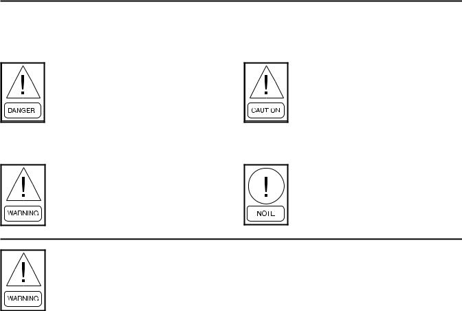
SAFETY SYMBOLS
The following symbols are used in this document to alert the reader to areas of potential hazard:
DANGER indicates an imminently hazardous situation which, if not avoided, will result in death or serious injury.
WARNING indicates a potentially hazardous situation which, if not avoided, could result in death or serious injury.
CAUTION identifies a hazard which could lead to damage to the machine, damage to other equipment and/or environmental pollution. Usually an instruction will be given, together with a brief explanation.
NOTE is used to highlight additional information which may be helpful to you.
External wiring, unless specified as an optional connection in the manufacturer’s product line, is not to be connected inside the micro panel cabinet. Devices such as relays, switches, transducers and controls may not be installed inside the micro panel. No external wiring is allowed to be run through the micro panel. All wiring must be in accordance with YORK’s published specifications and must be performed only by qualified YORK personnel. YORK will not be responsible for damages/problems resulting from improper connections to the controls or application of improper control signals. Failure to follow this will void the manufacturer’s warranty and cause serious damage to property or injury to persons.
2 |
YORK INTERNATIONAL |

FORM 50.40-OM2
CHANGEABILITY OF THIS DOCUMENT
In complying with YORK’s policy for continuous product improvement, the information contained in this document is subject to change without notice. While YORK makes no commitment to update or provide current information automatically to the manual owner, that information, if applicable, can be obtained by contacting the nearest YORK Applied Systems Service office.
It is the responsibility of operating/service personnel as to the applicability of these documents to the equipment in question. If there is any question in the mind of operating/service personnel as to the applicability of these documents, then, prior to working on the equipment, they should verify with the owner whether the equipment has been modified and if current literature is available.
YORK INTERNATIONAL |
3 |

TABLE OF CONTENTS
SECTION |
1 |
PRODUCT DESCRIPTION ....................................................................... |
8 |
|
|
Chiller/Condensing Control Panel(s) .......................................................... |
9 |
SECTION |
2 |
INSTALLATION........................................................................................ |
10 |
|
|
Mounting .................................................................................................. |
10 |
|
|
Installation Checklist ................................................................................ |
10 |
|
|
Wiring ................................................................................................... |
10 |
|
|
Lan Transient Installation ......................................................................... |
14 |
|
|
Eprom Compatibility ................................................................................ |
14 |
|
|
Troubleshooting ....................................................................................... |
14 |
|
|
Safety ................................................................................................... |
14 |
|
|
Proper Installation Practices ..................................................................... |
15 |
SECTION |
3 |
OPERATION............................................................................................. |
18 |
|
|
OptiView Remote Control Center ............................................................. |
18 |
|
|
Screen Descriptions and Usage................................................................. |
19 |
|
|
Home Screen............................................................................................. |
22 |
|
|
Unit Screen .......................................................................................... |
24 |
|
|
Systems Screen............................................................................... |
29 |
|
|
Individual System Screen.......................................................... |
32 |
|
|
Hours/Starts Screen ........................................................................ |
34 |
|
|
Options Screen ............................................................................... |
36 |
|
|
Trending Screen ............................................................................. |
38 |
|
|
Trend Setup Screen ................................................................... |
40 |
|
|
Setpoints Screen ............................................................................. |
44 |
|
|
History Screen ................................................................................ |
47 |
|
|
History Details Screen .............................................................. |
48 |
|
|
RCC Setpoints Screen ......................................................................... |
49 |
|
|
RCC Setup Screen .......................................................................... |
50 |
|
|
Comms Screen .......................................................................... |
52 |
|
|
Printer Screen ............................................................................ |
53 |
|
|
Diagnostics Screen .................................................................... |
54 |
|
|
Diagnostics (I/O) Screen ..................................................... |
55 |
|
|
Diagnostics (RCC Comms) Screen ..................................... |
56 |
|
|
Display Messages ..................................................................................... |
58 |
SECTION |
4 |
PRINTERS ............................................................................................... |
59 |
SECTION |
5 |
SERVICE ................................................................................................. |
65 |
|
|
Introduction............................................................................................... |
65 |
4 |
YORK INTERNATIONAL |

|
|
FORM 50.40-OM2 |
|
System Architecture.................................................................................. |
66 |
|
Microboard................................................................................................ |
68 |
|
Microboard Program Jumpers .................................................................. |
76 |
|
Microboard Program Switches ................................................................. |
78 |
|
Liquid Crystal Display.............................................................................. |
81 |
|
Display Interface Board ............................................................................ |
87 |
|
Display Backlight Inverter Board ............................................................. |
89 |
|
Keypad .................................................................................................... |
91 |
|
Power Supply............................................................................................ |
94 |
|
Offline Diagnostics & Troubleshooting.................................................... |
96 |
|
Main Diagnostics ...................................................................................... |
97 |
|
Keypad Test............................................................................................... |
98 |
|
Display Test .............................................................................................. |
99 |
|
Bit Pattern Test ....................................................................................... |
100 |
|
Serial Inputs / Outputs Tests ................................................................... |
101 |
|
Digital Inputs / Outputs Tests ................................................................. |
103 |
|
Analog Inputs Test .................................................................................. |
104 |
|
System Commissioning Checklist .......................................................... |
105 |
SECTION 6 |
PART NUMBER AND RENEWAL PARTS........................................... |
106 |
|
|
LIST OF TABLES |
|
TABLE 1 |
– |
Required Software Version of the Chiller/Condensing Unit Eproms |
..........11 |
TABLE 2 |
– |
Program Jumpers ......................................................................................... |
76 |
TABLE 3 |
– |
Program Switches ........................................................................................ |
78 |
TABLE 4 |
– |
Part Number ............................................................................................... |
106 |
TABLE 5 |
– |
Renewal Parts ............................................................................................ |
106 |
YORK INTERNATIONAL |
5 |
LIST OF FIGURES
FIG. 1 |
– EU DECLARATION OF CONFORMITY ............... |
7 |
|
FIG. 2 |
– |
FIELD WIRING ................................................... |
12 |
FIG. 3 |
– |
CONTROL INSTALLATION ................................ |
16 |
FIG. 4 |
– |
GROUNDING ..................................................... |
16 |
FIG. 5 |
– |
SEPARATE CONDUIT INSTALLATION .............. |
17 |
FIG. 6 |
– POWER & GROUND WIRE CONNECTIONS .... |
17 |
|
FIG. 7 |
– OPTIVIEW REMOTE CONTROL CENTER ....... |
18 |
|
FIG. 8 |
– |
SCREEN NAVIGATION LAYOUT ....................... |
20 |
FIG. 9 |
– |
HOME SCREEN................................................. |
22 |
FIG. 10 |
– |
UNIT SCREEN ................................................... |
24 |
FIG. 11 |
– |
SYSTEMS SCREEN .......................................... |
29 |
FIG. 12 |
– |
INDIVIDUAL SYSTEM SCREEN........................ |
32 |
FIG. 13 |
– HOURS AND STARTS SCREEN ....................... |
34 |
|
FIG. 14 |
– |
OPTIONS SCREEN ........................................... |
36 |
FIG. 15 |
– |
TRENDING SCREEN......................................... |
38 |
FIG. 16 |
– |
TRENDING SETUP SCREEN............................ |
40 |
FIG. 17 |
– |
SETPOINTS SCREEN ....................................... |
44 |
FIG. 18 |
– |
HISTORY SCREEN............................................ |
47 |
FIG. 19 |
– |
HISTORY DETAILS SCREEN ............................ |
48 |
FIG. 20 |
– |
RCC SETPOINTS SCREEN .............................. |
49 |
FIG. 21 |
– |
RCC SETUP SCREEN....................................... |
50 |
FIG. 22 |
– |
COMMS SCREEN.............................................. |
52 |
FIG. 23 |
– |
PRINTER SCREEN............................................ |
53 |
FIG. 24 |
– |
DIAGNOSTICS SCREEN................................... |
54 |
FIG. 25 |
– |
DIAGNOSTICS I/O SCREEN ............................. |
55 |
FIG. 26 |
– DIAGNOSTICS RCC COMMS SCREEN ........... |
56 |
|
FIG. 27 |
– |
PRINTERS ......................................................... |
59 |
FIG. 28 |
– EXAMPLE PRINTOUT (OPERATING DATA)...... |
63 |
|
FIG. 29 |
– EXAMPLE PRINTOUT (HISTORY HEADER) .... |
64 |
|
FIG. 30 |
– CONTROL CENTER BLOCK DIAGRAM ........... |
67 |
|
FIG. 31 |
– |
MICROBOARD ................................................... |
73 |
FIG. 32 |
– |
FLASH MEMORY CARD.................................... |
74 |
FIG. 33 |
– |
BLOCK DIAGRAM, MICROBOARD .................. |
75 |
FIG. 34 |
– MICROBOARD LAMP DIMMER CIRCUIT ......... |
78 |
|
FIG. 35 |
– SERIAL DATA COMMUNICATIONS PORTS...... |
79 |
|
FIG. 36 |
– |
CONFIGURABLE ANALOG INPUTS ................. |
80 |
FIG. 37 |
– |
DISPLAY, MOUNTING........................................ |
84 |
FIG. 38 |
– LCD TYPICAL CONTROL SIGNAL TIMING ...... |
84 |
|
FIG. 39 |
– LG SEMICON LP104V2 DISPLAY ASSEMBLY - 85 |
||
FIG. 40 |
– SHARP LQ10D367 DISPLAY ASSEMBLY - ...... |
85 |
|
FIG. 41 |
– SHARP LQ10D367 BACKLIGHT LAMP |
|
|
|
|
REPLACEMENT ................................................ |
86 |
FIG. 42 |
– LG SEMICON LP104V2 BACKLIGHT LAMP |
|
|
|
|
REPLACEMENT................................................. |
86 |
FIG. 43 |
– |
DISPLAY INTERFACE BOARD .......................... |
88 |
FIG. 44 |
– DISPLAY BACKLIGHT INVERTER BOARD....... |
90 |
|
FIG. 45 |
– |
KEYPAD ............................................................. |
92 |
FIG. 46 |
– |
DIAGRAM, KEYPAD........................................... |
93 |
FIG. 47 |
– BLOCK DIAGRAM, DC POWER DISTRIBUTION. 95 |
||
FIG. 48 |
– |
MAIN DIAGNOSTIC SCREEN ........................... |
97 |
FIG. 49 |
– |
KEYPAD TEST SCREEN ................................... |
98 |
FIG. 50 |
– |
DISPLAY TEST SCREEN................................... |
99 |
FIG. 51 |
– BIT PATTERNS TEST SCREEN....................... |
100 |
|
FIG. 52 |
– |
SERIAL INPUTS/OUTPUTS TESTS SCREEN 101 |
|
FIG. 53 |
– |
DIGITAL INPUTS/OUTPUTS TESTS SCREEN 103 |
|
FIG. 54 |
– ANALOG INPUTS TEST SCREEN .................. |
104 |
|
FIG. 55 |
– FRONT OF OPTIVIEW RCC............................ |
107 |
|
FIG.56 |
– INSIDE OF OPTIVIEW RCC ............................ |
107 |
|
FIG.57 |
– INSIDE DOOR OF OPTIVIEW RCC ................ |
108 |
|
FIG.58 |
– LOCATION OF FUSE, F1 & F2 ........................ |
109 |
|
6 |
YORK INTERNATIONAL |

FORM 50.40-OM2
FIG. 1 – EU DECLARATION OF CONFORMITY
YORK INTERNATIONAL |
7 |

Product Description
SECTION 1 – PRODUCT DESCRIPTION
The YORK OptiView Remote Control Center is a microprocessor based control system capable of remotely monitoring certain chillers and condensing units. It can monitor and individually control 1 to 8 of these chiller/condensing units.
The panel comes configured with a full screen color LCD Graphic Display mounted in the middle of a keypad interface. The graphic display allows the presentation of the current information all at once. In addition, the operator may view a graphical representation of several operating parameters. For the novice user, the locations of various parameters are clearly and intuitively marked. Instructions for specific operations are provided on many of the screens.
The graphic display also allows information to be represented in Imperial units (temperatures in °F and pressures in PSIG or PSID) or SI units (temperatures in °C and pressures in BARG or BARD).
All values that are modifiable at the Remote Control Center are recorded in memory and preserved even through a power failure condition. During operation, the chillers are continually polled and the user is advised of the operating conditions by various status and warning messages. A complete listing of shutdown, status, and warning messages is within the chiller/condensing unit’s operation manual.
If the chiller/condensing unit is in remote control mode the OptiView Remote Control Center provides the capability to program the following:
1.Start Command
2.Stop Command
3.Local Setpoint
4.Local Control Range
5.Daily/Holiday Schedule
6.Current or Load Limit Setpoint
The Remote Control Center is also designed to enable the user to obtain chiller/condensing unit printouts directly from this panel.
This equipment has been tested and found to comply with the limits for a Class A digital device, pursuant to part 15 of the FCC Rules. These limits are designed to provide reasonable protection against harmful interference when the equipment is operated in a commercial environment. This equipment generates, uses, and can radiate radio frequency energy and, if not installed and used in accordance with the instruction manual, may cause harmful interference to radio communications. Operation of this equipment in a residential area is likely to cause harmful interference in which case the user will be required to correct the interference at his own expense.
8 |
YORK INTERNATIONAL |

CHILLER/CONDENSING CONTROL PANEL(S)
All communication with the chiller/condensing units will occur over a single RS-485 port. Reference Figure 2 and the Installation instructions.
When the OptiView RCC is first turned on it will initialize by requesting current data and history buffer information from the units connected. After the history buffers are filled, only current data will be continuously requested. Every eight hours the OptiView RCC will reinitialize. If the control panel updates the history buffer (a safety shutdown has occurred), the control panel will send the chiller shutdown data to the OptiView RCC upon receipt of the next valid OptiView RCC transmission. The OptiView RCC will recognize that a safety shutdown has occurred by the Update History Buffer bit being set. If this bit is ever 1, the data dump is assumed to be a shutdown data dump and the OptiView RCC will update its history buffers with the new data and start a printout of the transmitted data through its RS232 port. If the OptiView RCC had been requesting another type of data dump (i.e. a daily schedule dump), the OptiView RCC will repeat its request on the next transmission.
While at the Home Screen, the OptiView RCC will communicate with each unit in order. Once a unit has been selected by entering the Unit Screen or any screen below it, that unit will be polled between every unit in order. This will allow the selected unit to update its information quickly while still maintaining information for the Home Screen.
A command string is used to indicate what data the OptiView RCC is requesting and to modify control data in the chiller control panel. If the chiller/condensing unit is in remote control mode then its Local Set Point, Local Range, Daily Schedule, Holiday, Start
FORM 50.40-OM2
/ Stop Command, and Current / Load Limit can be programmed from the OptiView RCC. The OptiView RCC will send a command string once any of these are
modified at the OptiView RCC. If the OptiView RCC 1 sends a Stop command, the chiller/condensing unit will
turn off. If the OptiView RCC sends a start command, the chiller/condensing unit will be allowed to run if all the other run requirements of the unit are made.
A chiller/condensing unit that is in remote control mode will use local control (set points and start / stop information), if a valid transmission has not been received for 5 minutes from the OptiView RCC. The remote commands will be used again once a valid new transmission has been processed. The OptiView RCC will display an error message indicating the communications problem when such a condition occurs.
A general status message for each unit is displayed on the Home Screen. The messages displayed will include communications status. Not Initialized will be displayed upon power-up for all units until the OptiView RCC begins to poll and receive data from that unit. Initializing… will be displayed while the OptiView RCC is polling a unit for all current, schedule, and history data the first time after power-up. Loss of Comms will be displayed after 5 minutes have elapsed with no response from a previously initialized unit. If any of these messages is displayed, the unit’s button will be disabled not allowing it to be selected.
The Control Center Microboard (J12) communicates with this board via a 0/+5VDC serial data communications link. If this communications link does not operate properly, correct Microboard J12 serial port operation can be verified using the Serial Inputs and Outputs diagnostic procedure in the “Service” section of this book.
YORK INTERNATIONAL |
9 |

Installation
SECTION 2 – INSTALLATION
MOUNTING
Mount the Remote Control Center at a level that provides for easy viewing of the color graphic display by all users. Securely mount it at the desired location. The panel may be mounted away from the chiller as far as 4000 ft. (1219 m.) of wiring will allow.
INSTALLATION CHECKLIST
(Reference Fig. 2 for wiring)
•A communications cable must connect the OptiView RCC to the chiller/condenser control panel. This cable should be a three-conductor with foil shield and drain wire, 20 awg or larger wire, 300v, 80 Deg. C, UL Style 2464, UL listed and CSA approved. Three sources are Alpha 5463, Belden 9364, or Quabbin 0220. The cable length (sum of lengths of all cables) must not exceed 4000 ft. (1219 m.). The cable is user supplied.
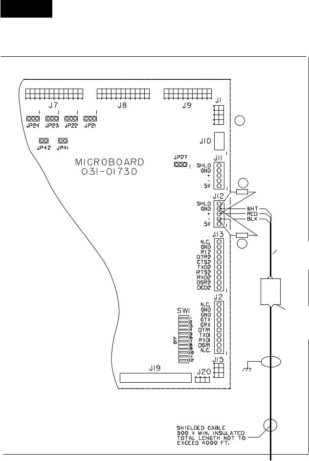
•Obtain ferrite (part number 025-35154-000) from the cloth bag found in the OptiView RCC and install it as shown on Fig. 2. This must be installed to meet FCC and CE requirements.
•Make sure that the Transient Voltage Suppressors are installed at J12. One is installed from “+” to “GND” and one is installed from “-” to “GND”.
•At J12 of the OptiView RCC, red wire on RS485(+), black wire on RS485(-) and white wire on Ground.
•At the OptiView RCC, connect the shield to the panel.
•Use a tie wrap between the J12 connector and the Ferrite (part number 025-35154-000) to secure the shielded cable to the OptiView RCC. The tie wrap can help prevent the wires from being accidentally pulled out of the J12 connector by someone working in the panel or by the weight of the ferrite.
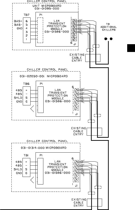
•Install a LAN transient protection module at the chiller/condenser control panel and connect the cable according to the type of control panel.
•Make sure the correct EPROM is installed at the chiller/condenser control panel(s). See Table 1.
•From the Setpoints Screen of the OptiView RCC, enter the Number of Units Connected (Maximum value allowed is 8).
•At the chiller/condenser control panel that uses a rotary switch to set the ID, use a small screw driver to rotate the rotary switch so that the arrow points at the number that coincides with the Unit’s Identification number (ID#). Unit 1 - Unit 8 coincide to rotary switches 0 - 7. Otherwise program the panel’s ID through keypad entry.
Never skip an ID#. For example, if you have four units then they must be identified from ID#0 - ID#3.
•At the chiller/condenser unit’s control panel, select the type of control mode. Select REMOTE only if remote control is desired. Select LOCAL to only monitor this unit.
•From the Comms Screen of the OptiView RCC, enter the RCC Poll Time. This is how often (time in seconds) to request data. This time should be set long enough to allow for receiving the data.
WIRING
A communications cable must connect the chiller to the remote panel. This cable should be a three-conductor with foil shield and drain wire, 20 awg or larger sized wire, 300v, 80 Deg. C, U.L. Style 2464, U.L. listed and CSA approved. Three sources are Alpha 5463, Belden 9364, or Quabbin 0220. The cable length (sum of lengths of all cables) must not exceed 4000 ft. (1219 m.).
Never run the communication cable in close proximity to any power wiring. For best results, it should be run in dedicated, grounded conduit. See Proper Installation Practices.
10 |
YORK INTERNATIONAL |
FORM 50.40-OM2
REQUIRED SOFTWARE VERSION OF THE
CHILLER / CONDENSING UNIT EPROMS
TABLE 1 – REQUIRED SOFTWARE VERSION OF THE CHILLER/CONDENSING UNIT EPROMS
UNIT TYPE |
|
EPROM PART NO. |
VERSION |
|
|
YCAL / YCUL w/microboard 031-01314-000 |
031-02011-001 |
C.MMC.01.05 |
|
||
|
|
|
|
||
YCAL / YCUL w/microboard 031-02050-000 |
031-02049-001 |
C.MMC.03.02 |
|
||
|
|
|
|
|
|
YCAS - F 2 |
Compressors |
031-01798-001 |
C.ACS.09.03 |
|
|
YCAS - F 3 |
& 4 Compressors |
031-01798-002 |
C.ACS.10.02 |
|
|
|
|
|
|
2 |
|
YCAR 2 Compressors |
031-02013-001 |
C.RCP.23.02 |
|||
|
|||||
|
|
|
|
|
|
The software version is printed on a label adhered to the EPROM chip’s surface. A revision level higher than the one listed in the table is acceptable. An example version code is as follows:
C.ACS. 09. XX.
Revision Level. Increments 01, 02 etc.
Product Code
YCAS (RCP = YCAR, MMC =YCAL/YCUL)
Commercial
YORK INTERNATIONAL |
11 |
Installation
OPTIVIEW REMOTE CONTROL CENTER
A Transient Voltage
Suppressor (031-02076-000) (Factory Installed)
A
A
Tie Wrap (To help  keep wires
connected)
Ferrite (025-35154-000) (FCC & CE Requirement)
LD06725
FIG. 2 – FIELD WIRING OPTIVIEW RCC PANEL
12 |
YORK INTERNATIONAL |
|
|
|
|
FORM 50.40-OM2 |
|
|
|
RED |
|
|
|
|
BLK |
|
|
|
|
SHLD |
(TOTAL NOT TO |
|
|
|
WHT |
|
|
|
(COMPONENT |
EXCEED 8) |
|
|
|
|
||
|
|
SIDE UP) |
|
|
|
|
|
|
2 |
|
|
|
RED |
|
|
|
|
BLK |
|
|
|
|
SHLD |
|
|
|
(COMPONENT |
WHT |
|
CUT PINS |
X |
|
|
|
X |
SIDE DOWN) |
|
|
|
AS SHORT |
|
|
|
|
AS POSSIBLE |
|
|
|
|
|
|
|
RED |
|
|
|
|
BLK |
|
|
|
|
SHLD |
|
|
|
(COMPONENT |
WHT |
|
CUT PINS |
X |
|
|
|
|
SIDE DOWN) |
|
|
|
AS SHORT |
X |
|
|
|
|
|
|
||
AS POSSIBLE |
|
|
|
|
FROM |
|
|
|
|
OPTIVIEW RCC |
|
|
|
|
|
|
|
|
LD06726 |
FIG. 2 – FIELD WIRING OPTIVIEW RCC PANEL (CONT.)
YORK INTERNATIONAL |
13 |

Installation
LAN TRANSIENT INSTALLATION
The properly installed Lan Transient Protection Module, (part number 031-01586-000) will limit the voltage levels seen by the chiller control panel’s RS-485 driver while allowing normal RS-485 network operation under non-transient conditions. For installation of the module refer to Fig. 2 and the specific installation instructions for the microboard.
Unit Microboard 031-01314-000 and 031-02050-001:
Step 1: Label all wires, cables, or components connected to TB1.
Step 2: Carefully loosen each terminal of TB1. Remove all wires, cables, or components. Be extremely careful to not allow them to short together or to the enclosure.
Step 3: Refer to the Module. Replace all wires, cables, or components taken from TB1 into the correct terminals of the Module terminal strip J1 being extremely careful to not allow them to short together or to the enclosure.
Step 4: Carefully tighten all screws on the Module Terminal strip J1.
Step 5: Orient the Module as shown (component side down) and cut the unused pins. Insert the four P1 Module pins into TB1 as shown.
Step 6: Carefully tighten each terminal of TB1. Double check all wiring to the Module before closing up.
Unit Microboard 031-01095-000:
Step 1: Label all wires, cables, or components connected to TB7.
Step 2: Carefully loosen each terminal of TB7. Remove all wires, cables, or components. Be extremely careful to not allow them to short together or to the enclosure.
Step 3: Replace all wires, cables, or components taken from TB7 into the Module terminal strip J1 being extremely careful to not allow them to short together or to the enclosure.
Step 4: Carefully tighten all screws on the Module Terminal strip J1.
Step 5: Orient the Module as shown (component side up) and insert all six P1 Module pins into TB7 as shown.
Step 6: Carefully tighten each terminal of TB7. Double check all wiring to the Module before closing up.
EPROM COMPATIBILITY
Since the concept and design of the OptiView Remote Control Center may have occurred after the original EPROM (software) for the chiller/condenser control panel, the EPROM may need to be replaced with one that allows for OptiView Remote Control Center operation. See Table 1.
TROUBLESHOOTING
From the Home Screen you can determine if you are communicating to the chiller/condensing unit.
If the message Not Initialized.. remains shown on this screen, proper communication between the panels has not occurred and you will need to troubleshoot.
Step 1: If you are trying to communicate with more than one unit, simplify the troubleshooting by isolating the communication to one unit at a time. Remove any wiring to a secondary unit and from the Setpoints Screen of the OptiView RCC, enter one as the Number of Units Connected and at the chiller/condenser control panel set it’s ID to zero.
Step 2: Check if there is any communication problem occurring on the Diagnostic RCC Comms Screen. See the description of this screen.
You could also check that the RX3 I/O communication activity LED on the OptiView Main Processor Board is blinking as it receives data from the chiller/condensing unit’s control panel. A steady lit RX3 LED is a sign of improper wiring. If the RX3 LED is not blinking check the wiring and the installation of the Lan Transient Protection Module. If everything is properly connected replace the 485 driver on the chiller/condenser microboard (part number 031-02074-000).
SAFETY
It is recommended that all maintenance and service repair work be performed by experienced personnel. There must be recognition of the potential hazards that can exist. Those hazards may include (but are not limited to):
14 |
YORK INTERNATIONAL |

There can be electrical circuitry that presents an electrocution hazard. Be sure that the sources of all power supplies have been properly isolated and secured before attempting any service related activities.
External wiring, unless specified as an optional connection in the manufacturer’s product line, is not to be connected inside the OptiView Remote Control Center cabinet. Devices such as relays, switches, transducers and controls may not be installed inside the OptiView Remote Control Center. No external wiring is allowed to be run through the OptiView Remote Control Center. All wiring must be in accordance with YORK’s published specifications and must be performed only by qualified YORK personnel. YORK will not be responsible for damages/problems resulting from improper connections to the controls or application of improper control signals. Failure to follow this will void the manufacturer’s warranty and cause serious damage to property or injury to persons.
PROPER INSTALLATION PRACTICES
Earlier relay systems were virtually immune to radio frequency interference (RFI), electromagnetic interference (EMI), and ground loop currents. Installation consisted of hooking up the point-to-point wiring and sizing the wire properly.
In an electronic system, improper installation will cause problems that outweigh the benefits of electronic control. Electronic equipment is susceptible to RFI, EMI, and ground loop currents which can cause equipment shutdowns, processor memory and program loss, erratic behavior, and false readings. Manufacturers of industrial electronic equipment take into consideration the effects of RFI, EMI, and ground loop currents and incorporate protection of the electronics in their designs. These manufacturers require that certain installation precautions be taken to protect the electronics from these effects. All electronic equipment must be viewed
FORM 50.40-OM2
as sensitive instrumentation and therefore requires careful attention to proper installation procedures.
There are a few basics, that if followed, will result in a trouble-free installation. The National Electric Code (N.E.C.) is a guideline for safe wiring practices, but it does not deal with procedures used for electronic control installation. Use the following procedures for electronic equipment installation. These procedures are to be used in conjunction with the N.E.C.
Wire Sizing |
2 |
Size supply wires one size larger than required for amperage draw to reduce instantaneous voltage dips caused by large loads such as heaters, contactors and solenoids. Sudden dips in voltage can cause the processor to momentarily malfunction or cause a complete reset of the control system. If the wire is loaded to its maximum capacity, the voltage dips are much larger, and the potential for a malfunction is very high. If the wire is sized one size larger than required, the voltage dips are smaller than in a fully loaded supply wire, and the potential for malfunction is much lower.
The NEC code requires specific wire sizes to be used based on current draw. An example would be to use #14 gauge wire for circuits up to 15 amp or #12 gauge wire for circuits of up to 20 amp. Therefore, when connecting the power feed circuit to an electronic industrial control, use #12 gauge wire for a maximum current draw of 15 amp and #10 wire for a maximum current draw of 20 amp.
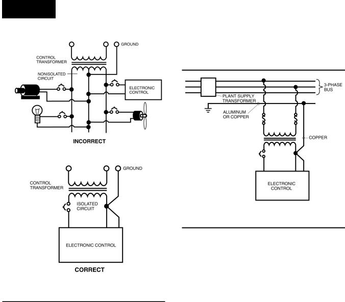
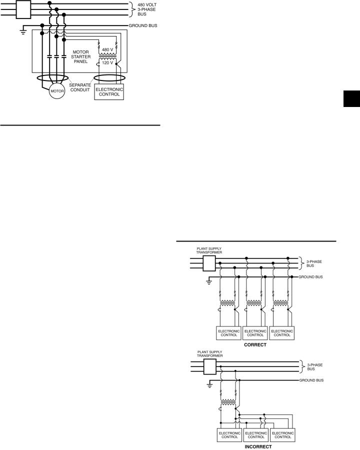
Voltage Source (Figure 3)
Selecting the voltage source is extremely important for proper operation of electronic equipment in an industrial environment. Standard procedure for electronic instrumentation is to provide a “clean” separate source voltage in order to prevent EMI, from other equipment in the plant, from interfering with the operation of the electronic equipment. Connecting electronic equipment to a breaker panel (also known as lighting panels and fuse panels) subjects the electronic equipment to noise generated by other devices connected to the breaker panel. This noise is known as electromagnetic interference (EMI). EMI flows on the wires that are common to a circuit. EMI cannot travel easily through transformers and therefore can be isolated from selected circuits. Use a control transformer to isolate the electronic control panel from other equipment in the plant that generate EMI.
YORK INTERNATIONAL |
15 |
Installation
equipment in the plant on the same circuits will ground themselves to the ground stake causing large ground flow at the electronic equipment.
LD06727
FIG. 3 – CONTROL INSTALLATION
Grounding
Grounding is the most important factor for successful operation. Electronic equipment reacts to very small currents and must have a good ground in order to operate properly. The NEC states that control equipment may be grounded by using the rigid conduit as a conductor. This is not acceptable for electronic control equipment. Conduit is a poor conductor compared to a copper wire. Copper grounds are required for proper operation.
Ground Wire Size (Figure 4)
The ground wire must be the same size as the supply wires or one size smaller as a minimum. The three phase power brought into the plant must also have a ground wire, making a total of four wires. In many installations that are having electronic control problems, this essential wire is usually missing. A good ground circuit must be continuous from the plant source transformer to the electronic control panel for proper operation. Driving a ground stake at the electronic control will cause additional problems since other
LD06728
FIG 4 – GROUNDING
Wiring Practices (Figure 5)
Do not mix wires of different voltages in conduit. For an example refer to Figure 5. The motor voltage is 480 volts and the panel control power is 120 volts. The 480 volt circuit must be run from the motor starter to the motor in its own conduit. The 120 volt circuit must be run from the motor starter control transformer to the control panel in its own separate conduit. If the two circuits are run in the same conduit, transients on the 480 volt circuit will be inducted into the 120 volt circuit causing functional problems with the electronic control. Dividers must be used in wire way systems (conduit trays) to separate unlike voltages. The same rule applies for 120 volt wires and 220 volt wires. Also, never run low voltage wires in the same conduit with 120 volt wires.
Never run any wires through an electronic control panel that do not relate to the function of the panel. Electronic control panels should never be used as a junction box. These wires may be carrying large transients that will interfere with the operation of the control.
When running conduit to an electronic control panel, note that the access holes (knockouts) are strategically placed so that the field wiring does not interfere with the electronics in the panel. Never allow field wiring to come in close proximity with the controller boards since this will almost always cause problems.
16 |
YORK INTERNATIONAL |
LD06738
FIG. 5 – SEPARATE CONDUIT INSTALLATION
Do not drill a control panel to locate conduit connections. Drilling can cause metal chips to land in the electronics and create a short circuit. If you must drill the panel, take the following precautions:
1.Call the panel manufacturer, if possible, before drilling the panel to be sure you are entering the panel at the right place.
2.Cover the electronics with plastic. Tape the plastic to the board with masking or electrical tape.
3.Place masking tape or duct tape on the inside of the panel at the point of drill bit entry.
4.Remove all of the remaining chips from the panel before removing the protective plastic.
When routing conduit to the top of an electronic control panel, condensation must be taken into consideration. Water can condense in the conduit and run into the panel causing catastrophic failure. Route the conduit to the sides or bottom of the panel and use a conduit drain.
If the conduit must be routed to the top of the panel, use a sealable conduit fitting which is poured with a sealer after the wires have been pulled, terminated and the control functions have been checked. A conduit entering the top of the enclosure must have an “O” ring-type fitting between the conduit and the enclosure, so that if water gets on top of the enclosure, it cannot run in between the conduit and the enclosure. This is extremely important in outdoor applications.
Never add relays, starters, timers, transformers, etc. inside an electronic control panel without first contacting the manufacturer. Contact arcing and EMI emitted from these devices can interfere with the electronics. If you need to add these devices contact the manufacturer for the proper device types and placement.
FORM 50.40-OM2 |
|
Never run refrigerant, water or brine tubing inside |
|
an electronic control panel. A leak could damage or in |
|
some cases totally destroy the electronics. |
|
If the electronic control panel has a starter built into |
|
the same panel, be sure to run the higher voltage |
|
wires where indicated by the manufacturer. EMI |
|
from the wires can interfere with the electronics if run |
|
too close to the circuitry. |
|
Never daisy-chain or parallel-connect power or |
2 |
ground wires to electronic control panels. Each |
electronic control panel must have its own supply wires back to the power source. Multiple electronic control panels on the same power wires create current surges in the supply wires which can cause controller malfunctions. Daisy-chaining ground wires allows ground loop currents to flow between electronic control panels which also causes malfunctions. (See Figure 6)
It is very important to read the installation instructions thoroughly before beginning the project. Make sure you have drawings and instructions with your equipment. If not, call the manufacturer and have them send you the proper instructions. Following correct wiring procedures will ensure proper installation of your electronic equipment.
LD06739
LD06740
FIG. 6 – POWER & GROUND WIRE CONNECTIONS
YORK INTERNATIONAL |
17 |
Operation
SECTION 3 – OPERATION
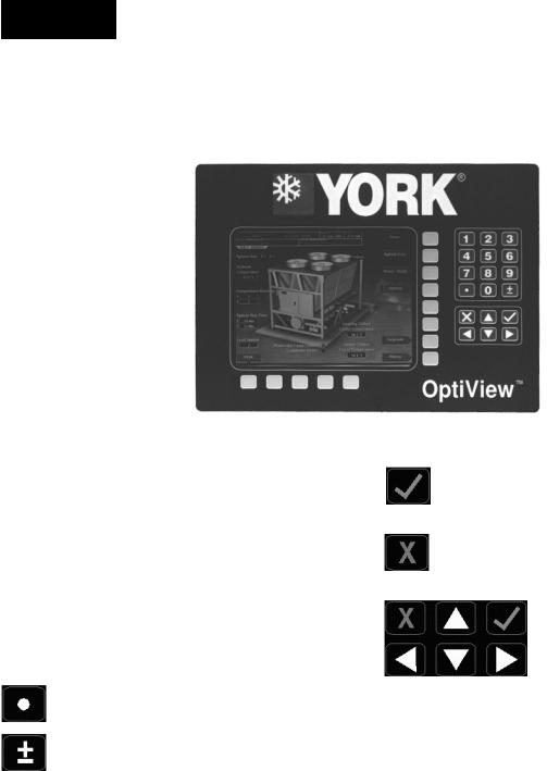
OPTIVIEW REMOTE CONTROL CENTER
FIG. 7 |
00500VIP |
|
The OptiView Remote Control Center display is highlighted by a full screen graphics display. This display is nested within a standard keypad, and is surrounded by “soft” keys which are redefined based on the currently displayed screen. Eight buttons are available on the right side of the panel, and are primarily used for navigation between the system screens. At the base of the display are 5 additional buttons. The area to the right of the keypad is used for data entry with a standard numeric keypad provided for entry of system setpoints and limits.
The Decimal key is used prior to entering decimal values.
A +/- key has also been provided to allow entry of negative values and AM/PM selection during time entry.
In order to accept changes made to the chiller setpoints, the Check key is provided as a universal ‘Enter’ key or ‘Accept’’ symbol.
In order to reject entry of a setpoint or dismiss an entry form, the ‘X’ key is provided as a universal ‘Cancel’ symbol.
Cursor Arrow keys are provided to allow movement on screens which contain a large amount of entry data. In addition, these keys can be used to scroll through history and event logs.
18 |
YORK INTERNATIONAL |

FORM 50.40-OM2
SCREEN DESCRIPTIONS AND USAGE
OVERVIEW
The new graphical display on each control panel allows a wide variety of information to be presented to the user. Each screen description in this document will begin with a section entitled Overview which will describe the graphical elements on the screen and give a short summary of the functions available. Each element on the screen will then be categorized into three distinct groups: Display Only, Programmable, and Navigation. Below is a short description of what types of information are included in these groups.
DISPLAY ONLY
Values in this group are read-only parameters of information about chiller operation. This type of information may be represented by a numerical value, a text string, or an LED image. For numerical values, if the monitored parameter is above the normal operating range, the high limit value will be displayed along with the ‘>’ symbol; if it is below the normal operating range, the low limit value will be displayed along with the ‘<’ symbol. In some cases, the value may be rendered invalid by other conditions and the display will use X’s to indicate this.
PROGRAMMABLE
Values in this group are available for change by the user if the chiller/condensing unit is in remote mode. If there are no values that can be changed then “None” is shown.
Setpoint / Change Schedule
On screens containing programmable setpoints, a key with one of these labels will be visible. This key allows the user to modify setpoints on that screen.
Setpoints
Setpoint values are used to control chillers/condensing units and other devices connected to the units. Setpoints can fall into several categories. They could be numeric values (such as 45.0°F for the Leaving Chilled Liquid Temperature), or they could Enable/Yes or Disable/No a feature or function.
Regardless of which setpoint is being programmed, the following procedure applies:
1.Press the desired setpoint key. A dialog box appears displaying the present value, the upper and lower limits of the programmable range, and the default value.
2.If the dialog box begins with the word “ENTER”, use the numeric keys to enter the desired value. Leading zeroes are not necessary. If a decimal point is necessary, press the ‘•’ key (i.e. 45.0).
Pressing the ▲ key, sets the entry value to the default for that setpoint. Pressing the ▼ key, clears the present entry. The ◄ key is a backspace key and causes the entry point to move back one space.
If the dialog box begins with “SELECT”, use the ◄ and ► keys to select the desired value.
If the previously defined setpoint is desired, press |
|
the ‘X’ (Cancel) key to dismiss the dialog box. |
3 |
3. Press the ‘ü’ (Enter) key. |
If the value is within range, it is accepted and the dialog box disappears. The chiller will begin to operate based on the new programmed value. If out of range, the value will not be accepted and the user is prompted to try again.
Manual Controls
Some keys are used to perform manual control functions. These may initiate/terminate processes such as a report.
Free Cursor
On screens containing many setpoints, a specific “soft” key may not be assigned to each setpoint value. A soft key will be assigned to enable the cursor arrow keys below the numeric keypad which are used to “highlight” the desired setpoint field. At this point, the ‘ü’ key is pressed to bring up a dialog prompting the user to enter a new setpoint value. The ‘X’ key cancels cursor mode. (See “Change Schedule” from the Setpoints Screen for an example.)
NAVIGATION
In order to maximize the amount of values which the panel can display to the user, and in order to place those values in context, multiple screens have been designed to describe each unit’s operation. In order to move from one screen to the next, navigation keys have been defined. These keys allow the user to either
YORK INTERNATIONAL |
19 |

Operation
move “forward” to a sub-screen of the present screen, or move “backward” to the previous screen. Except for the Home Screen display, the upper-right “soft” key will always return the user to the Home Screen. Navigating with “soft” keys is as simple as pressing the key next to the label containing the name of the desired screen. The system will immediately refresh the display with the graphics for that screen. Following is a layout of all the screens and how they are connected.
Home (page 22)
Unit Data (page 24)
System Data (page 29)
 Individual System (page 32)
Hours/Starts (page 34)
Options (page 36)
Trending (page 38)
Trend Setup (page 40)
Setpoints (page 44)
History (page 47)

 History Details (page 48)
RCC Setpoints (page 49)
 RCC Setup (page 50)
Comms (page 52)
Printer (page 53)
Diagnostics (page 54)
Diagnostics (I/O) (page 55)
Diag. (RCC Comms) (page 56)
FIG. 8 – SCREEN NAVIGATION LAYOUT
This section of the manual will describe each screen in the order they are accessed as shown in this screen navigation layout.
20 |
YORK INTERNATIONAL |
FORM 50.40-OM2
3
This page intentionally left blank to maintain formatting
YORK INTERNATIONAL |
21 |
Operation
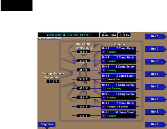
HOME SCREEN
FIG. 9 – HOME SCREEN - EXAMPLE
OVERVIEW
When the OptiView Remote Control Center is powered on, the above default display appears. This screen gives a general overview of the operating status of each unit connected to the OptiView Remote Control Center. The data and control of an individual unit is accessed from the Home Screen display. Fig. 9 is an example that shows eight units were programmed.
DISPLAY ONLY
Unit Control Temperature
Displays the temperature of what the unit is using for control such as leaving chilled liquid temperature. This is not shown if suction pressure is being used for control.
Unit Type
Displays the type of chiller the unit is.
Unit Status
Displays a general status message for the unit. The general status message will include communications status, running status, and fault status, etc. Following is a complete listing of the general status messages:
•Not Initialized will be displayed upon power-up for all units until the OptiView Remote Control Center begins to poll and receive data from that unit. While
00499VIPC
this message is displayed, the unit’s button will be disabled, not allowing it to be selected.
•Initializing… will be displayed while the OptiView Remote Control Center is polling a unit for all current, schedule, and history data the first time after power-up. While this message is displayed, the unit’s button will be disabled not allowing it to be selected.
•Loss of Comms will be displayed after 5 minutes have elapsed with no response from a previously initialized unit. While this message is displayed, the unit’s button will be disabled not allowing it to be selected.
•Running will be displayed when at least 1 system is running on a unit with no faults on any system. This message will be displayed even if the chiller is in any kind of limiting as long as there are no faults present. While this message is displayed, the unit’s button will be enabled allowing it to be selected.
•Not Running will be displayed when no systems on the unit are running for a non-fault reason but can run when demand requires. This would be for the No Cool Load state. While this message is displayed, the unit’s button will be enabled allowing it to be selected.
•Faulted will be displayed when no systems on the unit are running and there is a fault on one or more systems or a unit fault. While this message
22 |
YORK INTERNATIONAL |

is displayed, the unit’s button will be enabled allowing it to be selected.
•Running / Faulted will be displayed when at least one system on the unit is running and at least one system is faulted. While this message is displayed, the unit’s button will be enabled allowing it to be selected.
•Cannot Run will be displayed for any non-fault condition preventing the entire chiller from running. This would include such things as the daily schedule, unit switch, all system switches, run perm, etc. While this message is displayed, the unit’s button will be enabled allowing it to be selected.
Unit Run Indicator (LED)
Is ON when the unit is running.
Average Ambient Temperature
Displays the average Ambient Air Temperature of all the units connected.
FORM 50.40-OM2
PROGRAMMABLE
None
NAVIGATION
Unit #
A detailed view of data relevant to the specified (#) unit. If the “Not Initialized” status message is displayed, the unit’s button will be disabled, not allowing it to be selected.
Setpoints
This screen provides the gateway to many of the OptiView Remote Control Center’s general setup parameters such as Date/Time, Comm Setup, Printer Setup, etc.
3
YORK INTERNATIONAL |
23 |
Operation
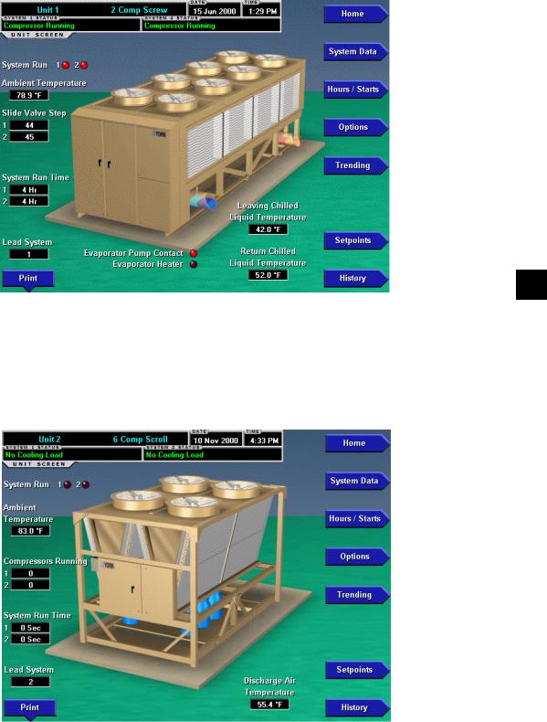
UNIT SCREEN - EXAMPLES
00569VIPC
FIG. 10A – YCAL CHILLER
00570VIPC
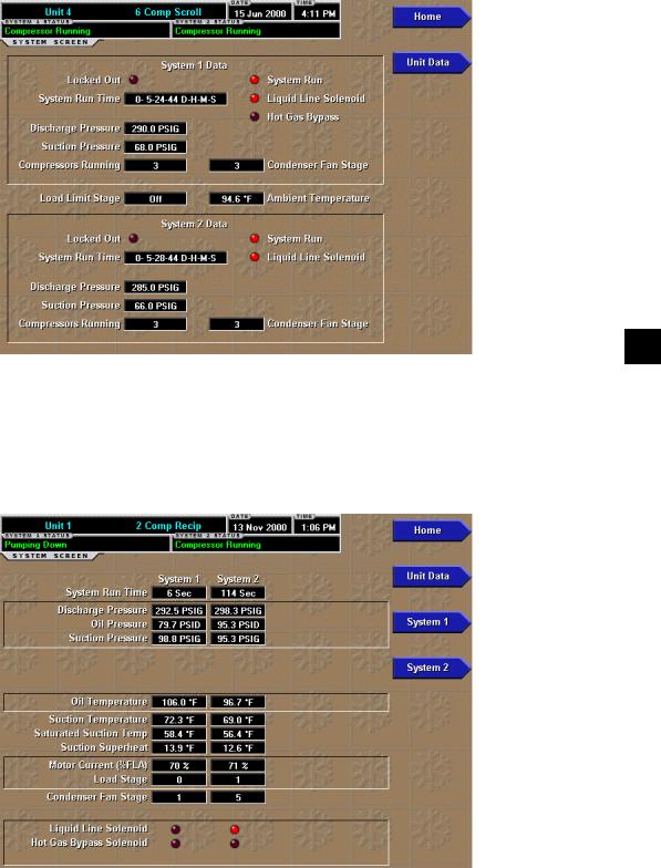
FIG. 10B – YCAR CHILLER
24 |
YORK INTERNATIONAL |
FORM 50.40-OM2
UNIT SCREEN - EXAMPLES
3
00571VIPC
FIG. 10C – YCAS CHILLER
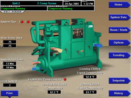
00572VIPC
FIG. 10D – YCUL CONDENSING UNIT
YORK INTERNATIONAL |
25 |
UNIT SCREEN - EXAMPLES
00573VIPC
FIG. 10E – YCWS CHILLER
26 |
YORK INTERNATIONAL |
FORM 50.40-OM2
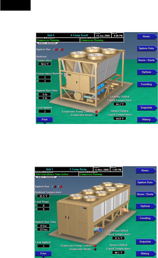
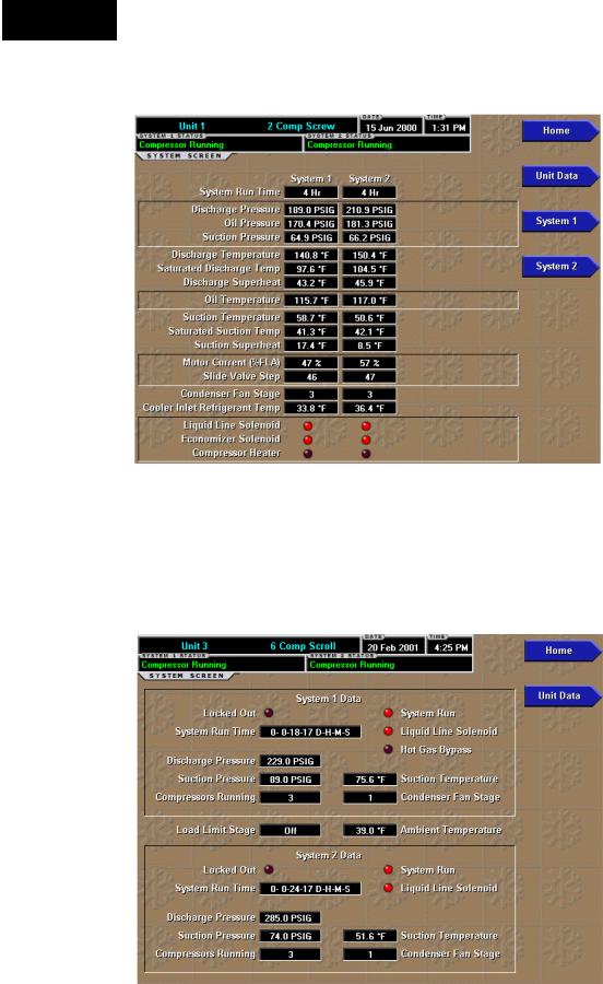
UNIT SCREEN
OVERVIEW
This screen is accessed from the Home Screen. The primary values of the chiller or condensing unit which must be monitored and controlled are shown on this screen. The data available depends on the type of unit. This screen display depicts a visual representation of the unit itself. Animation indicates chilled liquid flow and condenser fans running.
DISPLAY ONLY
Systems Statuses
Displays the individual refrigerant systems operational statuses. The messages displayed include running status, cooling demand, fault status, external cycling device status, load limiting, and anti-recycle timer status. The status message that is displayed on the microprocessor is represented here.
System Run (LED)
Is ON when the individual refrigerant systems compressor is running. If any of these are ON, the fans will be animated to show that they are running.
Slide Valve Step (If Screw)
Displays the individual refrigerant systems slide valve step.
Load Stage (If Recip)
Indicates the number of solenoids on the compressor of a YCAR unit that are de-energized and loaded.
Number Of Compressors Running (If a system has more than one)
Displays how many compressors are running on the unit.
System Run Time
Displays the individual refrigerant systems logged run time since the last compressor start, in days (Days), hours (Hr), minutes (Min) or seconds (Sec).
Lead System
This message indicates which system is in the lead.
Evaporator Pump Contact (LED)
Is ON when the evaporator pump signal from the microprocessor is on. If this is ON, the chilled liquid will be animated to show that it is flowing.
Evaporator Heater (LED)
Is ON when the evaporator heater signal from the microprocessor is on.
Leaving Chilled Liquid Temperature
Displays the temperature of the liquid as it leaves the evaporator.
Return Chilled Liquid Temperature
Displays the temperature of the liquid as it enters the evaporator.
Discharge Air Temperature
Displays the discharge air temperature leaving the evaporator when the condensing unit is programmed for Discharge Air control.
Systems Suction Pressure
Displays the suction pressure for each individual system on a condensing unit when the unit was programmed for Suction Pressure control.
Ambient Temperature
Displays the outdoor Ambient Air Temperature.
PROGRAMMABLE
Initiates a printout of current system operating parameters for the currently selected unit.
Cancel Print
Terminates the printing in process. This key is only visible while printing is in process.
NAVIGATION
Home
Causes an instant return to the Home Screen.
System Data
Used to provide additional system information.
Hours/Starts
This screen shows the cumulative operating hours and start count of each compressor.
Options
Used to provide information of the options that were programmed at the Unit Control Panel.
Trending
This screen provides the user a view of trending data on selected parameters of this chiller/condensing unit.
Setpoints
This screen provides a single location to program the unit setpoints for the selected unit.
History
This screen provides access to a snapshot of system data at each of the last 4-6 shutdown conditions.
YORK INTERNATIONAL |
27 |

Operation
This page intentionally left blank.
28 |
YORK INTERNATIONAL |
FORM 50.40-OM2
SYSTEMS SCREEN - EXAMPLES
3
FIG. 11A – YCAL CHILLER |
00505VIPC |
|
FIG. 11B – YCAR CHILLER |
00506VIPC |
|
YORK INTERNATIONAL |
29 |
Operation
SYSTEMS SCREEN - EXAMPLES
FIG. 11C – YCAS CHILLER |
00507VIPC |
|
FIG. 11D – YCUL CONDENSING UNIT |
00508VIPC |
|
Loading...