


GY9
036-21560-002 Rev. A (1204)
Heating Air Conditioning
TECHNICAL GUIDE
MODELS: GY9
GAS-FIRED
CONDENSING / HIGH EFFICIENCY
DOWNFLOW/HORIZONTAL FURNACES
91% AFUE
NATURAL GAS
40 - 120 MBH INPUT
EFFICIENCY
RATING
CERTIFIED
ISO 9001
Certified Quality
Management System
Due to continuous product improvement,
specifications are subject to change without notice.
Visit us on the web at www.york.com for the most
up-to-date technical information.
Additional rating information can be found at
www.gamanet.org.
R
DESCRIPTION
These Category IV, highly efficient, compact, condensing
type furnaces are designed for residential and commercial
installations in a basement, closet, alcove, recreation room or
garage where the ambient temperature is above 32°F, or
higher. They may be either side wall or thru-roof vented using
approved plastic type combustion air and vent piping. All
units are factory assembled, wired and tested to assure
dependable and economical installation and operation.
WARRANTY
Lifetime limited warranty on the heat exchanger.
10-year warranty on the heat exchanger in commercial
applications.
5-year limited parts warranty.
FEATURES
• Compact, easy to install, ideal height 40" cabinet
• Blower-off delay for cooling SEER improvement.
• Easy to connect power/control wiring.
• Built-in, high level self diagnostics with fault code display.
• Low unit amp requirement for easy replacement application.
• Integrated control module for reliable, economical operation.
• May be installed as either two-pipe (sealed combustion)
or single pipe vent (using indoor combustion air)
• Top intake & vent connection allows downflow installation in narrow locations.
• Electronic Hot Surface Ignition saves fuel cost with
increased dependability and reliability.
• Induced combustion system with inshot main burners for
quiet, efficient operation.
• No special vent termination kit required.
• 100% shut off main gas valve for extra safety.
• PSC -four speed, direct drive motor with large, quiet
blower.
• 24V , 40 V A control transformer and blower relay supplied
for add-on cooling.
• Hi-tech tubular aluminized steel primary heat exchanger.
• Secondary (condensing) heat exchanger of 29-4C highgrade stainless steel.
• Timed on, adjustable off blower capability for maximum
comfort.
• Easy access from front of unit for cleaning, maintenance
or service.
• Protection from intake, exhaust or condensate blockage.
• High velocity filters and filter racks provided for field
installation.
FOR DISTRIBUTION USE ONLY - NOT TO BE USED AT POINT OF RETAIL SALE
036-21560-002 Rev. A (1204)
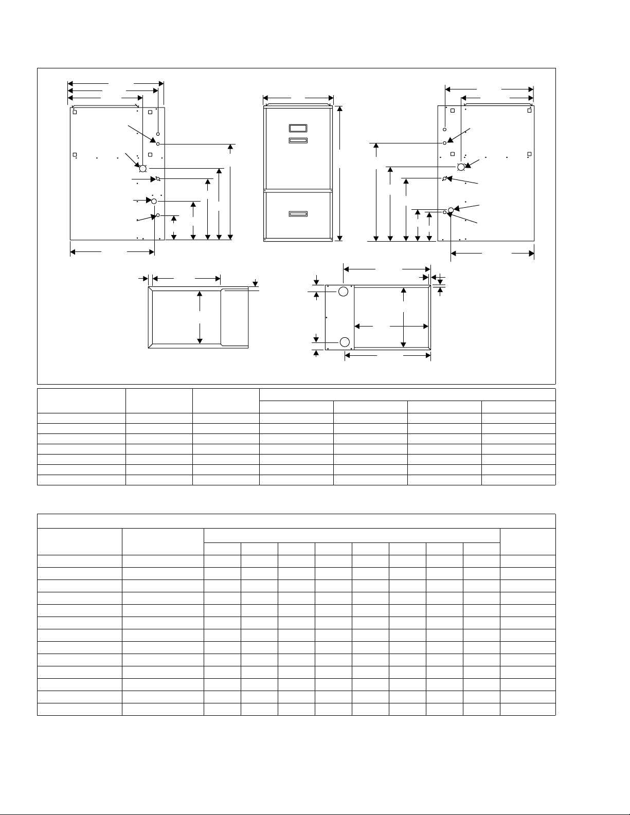
28-1/2
26-1/2
21-5/8
T’STAT WIRING
7/8” K.O.
HORIZONTAL
CONDENSATE
DRAIN 2” K.O.
7/8” JUNCTION
BOX HOLE
1-1/2” GAS
PIPE ENTRY
CONDENSATE
DRAIN 7/8” K.O.
24-5/8
1-1/4
18-1/2
11-11/16
7-1/2
19-1/4
C
BOTTOM IMAGE
SUPPLY END
21-7/8
A
D
2-1/4
40
29
21-9/16
18-1/2
23-5/8
B
20
23-1/4
TOP IMAGE
RETURN END
9-1/8
5/8
8-1/2
5/8
29
1-1/4
26-1/2
21-15/16
T’STAT WIRING
7/8” K.O.
HORIZONTAL
CONDENSATE
DRAIN 2” K.O.
7/8” JUNCTION
BOX HOLE
1-1/2” GAS
PIPE ENTRY
CONDENSATE
DRAIN 7/8” K.O.
25-3/8
Model Number CFM
Cabinet
Size
A (in.) B (in.) C (in.) D (in.)
Cabinet Dimension
GY9S040A12DH11 1200 A 14-1/2 13-1/4 12 1-3/4
GY9S060B12DH11 1200 B 17-1/2 16-1/4 15 1-3/4
GY9S080B12DH11 1200 B 17-1/2 16-1/4 15 1-3/4
GY9S080C16DH11 1600 C 21 19-3/4 18-1/2 2-1/8
GY9S100C16DH11 1600 C 21 19-3/4 18-1/2 2-1/8
GY9S100C20DH11 2000 C 21 19-3/4 18-1/2 2-1/8
GY9S120D20DH11 2000 D 24-1/2 23-1/4 22 2-1/2
COMBUSTION AIR SUPPLY AND VENT PIPING
MAXIMUM ELBOWS AND VENT LENGTHS
Models Input
BTUH
Pipe Size
Inches
1 2 3 4 5 6 7 8
40,000 1-1/2 25 20 15 10 N/A N/A N/A N/A 5
40,000 2 60555045403020N/A 5
40,000 3 8580757065605040 20
60,000 1-1/2 15 10 N/A N/A N/A N/A N/A N/A 5
60,000 2 6055504540352515 5
60,000 3 8580757065605040 20
80,000/1200 2 60 55 50 45 40 35 25 15 5
80,000/1200 3 85 80 75 70 65 60 50 40 20
80,000/1600 2 60 55 50 45 40 35 25 15 5
80,000/1600 3 85 80 75 70 65 60 50 40 20
100,000 2 25 20 15 10 N/A N/A N/A N/A 5
100,000 3 80 75 70 65 60 55 45 35 5
120,000 3 55 50 45 40 35 25 15 N/A 5
Three elbows (two in vent pipe and one in the air intake pipe) are already accounted for and need not be included in the elbow count
from the Table above.
Maximum Number of Elbows*
Minimum
Length
2 Unitary Products Group
ELECTRICAL AND PERFORMANCE DATA
ROOM
THERMOSTAT
FURNACE
CONTROL
CONDENSING
UNIT
TO AIR CONDITIONER
CONTROLS
R
W
G
Y
C
R
W
G
Y
C
036-21560-002 Rev. A (1204)
MODEL
NUMBER
Input Output
Nominal
Airflow
MBH MBH CFM In. °F
Cabinet
Width
Cabinet
Size
Air Temp.
Rise
APPROX.
OPER. WEIGHT
TOP RETURN
FILTER IN.
GY9S040A12DH11 40 37 1200 14-1/2 A 35 - 65 120 (2) 14 x 20
GY9S060B12DH11 60 55 1200 17-1/2 B 35 - 65 130 (2) 14 x 20
GY9S080B12DH11 80 74 1200 17-1/2 B 35 - 65 145 (2) 14 x 20
GY9S080C16DH11 80 74 1600 21 C 35 - 65 155 (2) 14 x 20
GY9S100C16DH11 100 93 1600 21 C 35 - 65 170 (2) 14 x 20
GY9S100C20DH11 100 93 2000 21 C 35 - 65 175 (2) 20 x 20
GY9S120D20DH11 120 112 2000 24-1/2 D 35 - 65 180 (2) 20 x 20
MODEL
NUMBER
Max.
AFUE
Outlet
Blower
Air Temp.
%°FHPAmpsIn.Amps
Blower
Size
Tot al Unit
Max.
Over-current
Protect
Min. Wire Size
(awg) @ 75 ft.
One Way
GY9S040A12DH11 91 165 1/2 7.0 11 x 8 9 20 14
GY9S060B12DH11 91 165 1/2 7.0 11 x 8 9 20 14
GY9S080B12DH11 91 165 1/2 7.0 11 x 8 9 20 14
GY9S080C16DH11 91 165 3/4 10.2 11 x 10 12 20 14
GY9S100C16DH11 91 165 3/4 10.2 11 x 10 12 20 14
GY9S100C20DH11 91 165 1 12.7 11 x 11 14 20 12
GY9S120D20DH11 91 165 1 12.7 11 x 11 14 20 12
Annual Fuel Utilization Efficiency (AFUE) numbers are determined in accordance with DOE Test procedures.
Wire size and over current protection must comply with the National Electrical Code (NFPA-70-latest edition) and all local codes.
The furnace shall be installed so that the electrical components are protected from water.
* Wire size and overcurrent protection must comply with the National Electric Code.
NOTES:
1. For altitudes above 2000 ft. reduce capacity 4% for each 1000 ft. above sea level.
2. Wire size based on copper conductors, 60°C, 3% voltage drop.
3. Continuous return air temperature must not be below 55°F.
4. All filters must be high velocity cleanable type.
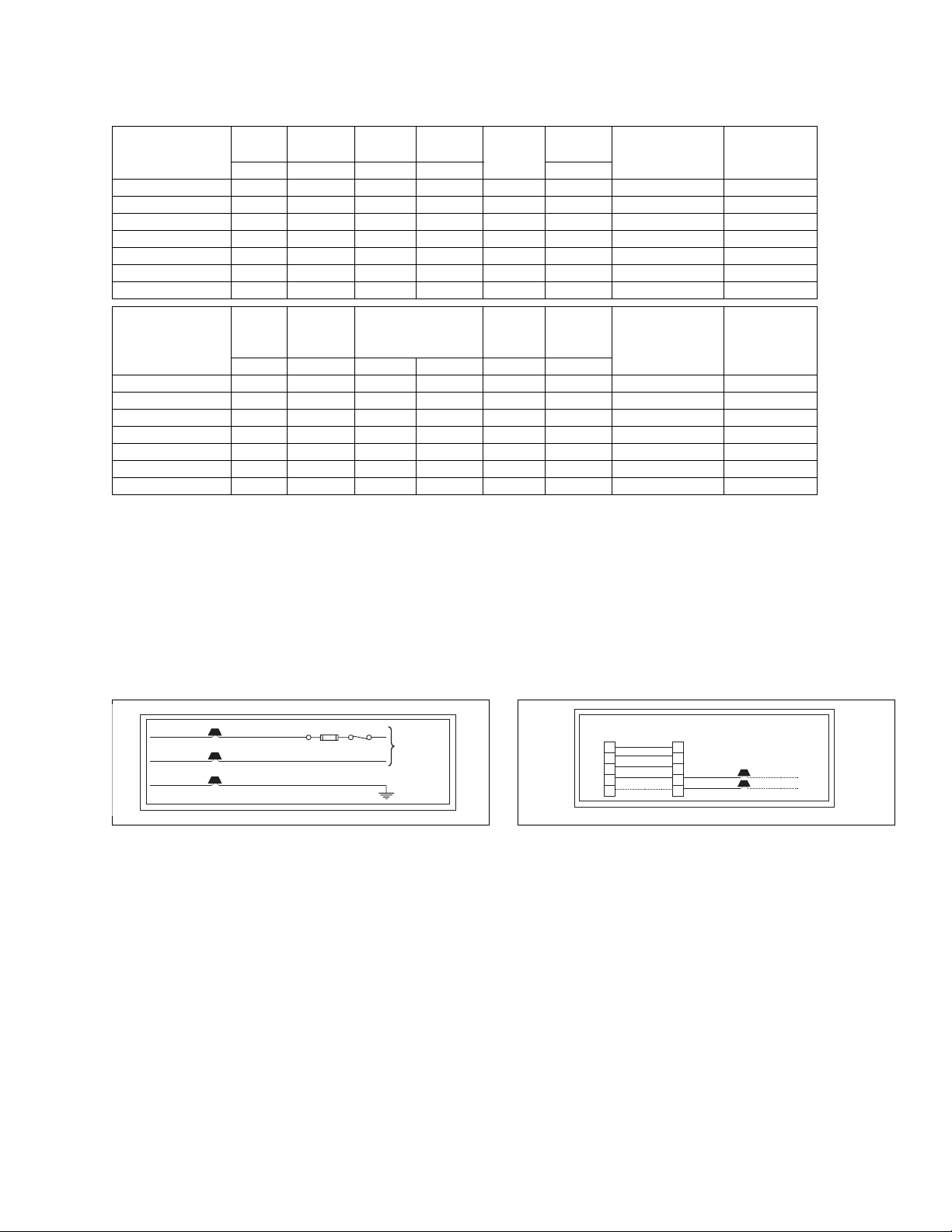
FIELD WIRING DIAGRAMS POWER WIRING
BLK
WHT
GRN
Unitary Products Group 3
BLK (HOT)
WHT (NEUTRAL)
GRD
NOMINAL
115 VOLT
 Loading...