


J |
CHAMPION® SERIES |
|
|
||
|
SINGLE PACKAGE AIR CONDITIONERS |
|
|
ELECTRIC/ELECTRIC, AIR-COOLED |
|
INSTALLATION INSTRUCTION Supersedes: 035-16703-000-A-0701 |
035-16703-001-A-0202 |
|
MODELS D1EB018 THRU 060
1-1/2 THRU 5 TON
(10 SEER)
GENERAL
Model D1EB units are factory assembled cooling only air conditioners designed for outdoor installation on a rooftop or a slab. Field-installed electric heater accessories are available to provide electric heat combined with electric cooling. All units and heaters are certified by AGA and CGA.
The units are completely assembled on rigid, but easily removable base rails. All piping, refrigerant charge, and electrical wiring is factory installed and tested. The units require only electric power and duct connections at the point of installation.
The electric heaters have nickel-chrome resistance wire elements and utilize single point power connection.
INSPECTION
As soon as a unit is received, it should be inspected for possible damage during transit. If damage is evident, the extent of the damage should be noted on the carrier's freight bill. A separate request for inspection by the carrier's agent should be made in writing. Refer to Form 50.15-NM for additional information.
REFERENCE
Additional information on the design, installation, operation and service of this equipment is available in the following reference forms:
•55.70-N1 -General Installation
•55.70-N2 -Pre-start & Post-start Check List
•511.26-N1.1V -Electric Heater Accessory
REPLACEMENT PARTS
•Refer to Replacement Parts Manual for complete listing of replacement parts on this equipment.
All forms referenced in this instruction may be ordered from:
Standard Register
Norman, OK 73069
Toll Free: Tel. 877-318-9675/Fax. 877-379-7920
Installer should pay particular attention to the words: NOTE, CAUTION and WARNING. Notes are intended to clarify or make the installation easier. Cautions are given to prevent equipment damage. Warnings are given to alert installer that personal injury and/or equipment damage may result if installation procedure is not handled properly.
CAUTION
THIS PRODUCT MUST BE INSTALLED IN STRICT COMPLIANCE WITH
THE ENCLOSED INSTALLATION INSTRUCTIONS AND ANY APPLICABLE
LOCAL, STATE, AND NATIONAL CODES INCLUDING, BUT NOT LIMITED
TO, BUILDING, ELECTRICAL, AND MECHANICAL CODES.
WARNING
INCORRECT INSTALLATION MAY CREATE A CONDITION WHERE THE OPERATION OF THE PRODUCT COULD CAUSE PERSONAL INJURY O R PRO PERT Y DAM AG E.
035-16703-001-A-0202
PRODUCT NOMENCLATURE
|
|
|
|
D |
|
1 |
|
E |
B |
|
0 |
2 |
4 |
|
A |
|
0 |
|
6 |
|
|
|
|
|
|
||||||
PRODUCT CATEGORY |
|
|
|
|
|
|
|
|
|
|
|
|
|
|
|
|
|
|
|
|
|
|
|
|
|
|
|
VOLTAGE CODE |
|
||
|
|
|
|
|
|
|
|
|
|
|
|
|
|
|
|
|
|
|
|
|
|
|
|
|
|
|
|||||
D = Single Package Air Conditioner |
|
|
|
|
|
|
|
|
|
|
|
NOMINAL COOLING |
|
|
|
|
|
|
06 = 208/230-1-60 |
|
|||||||||||
(Air Cooled) |
|
|
|
|
|
|
|
|
|
|
|
|
|
|
|
||||||||||||||||
|
|
|
|
|
|
|
|
|
|
|
|
|
|
|
|
|
25 = 208/230-3-60 |
|
|||||||||||||
|
|
|
|
|
|
|
|
|
|
CAPACITY (MBH) |
|
|
|
|
|
|
|
||||||||||||||
|
|
|
|
|
|
|
|
|
|
|
|
|
|
|
|
|
|
||||||||||||||
|
|
|
|
|
|
|
|
|
|
|
|
|
|
|
|
|
|
|
|
46 = 460-3-60 |
|
||||||||||
|
|
|
|
|
|
|
|
|
|
|
|
|
|
|
|
|
|
|
|
|
|
|
|
|
|
|
|
||||
|
|
|
|
|
|
|
|
|
|
|
|
|
|
018 = 18,000 BTUH |
|
|
|
|
|||||||||||||
PRODUCT GENERATION |
|
|
|
|
|
|
|
|
|
|
|
|
|
|
|
|
|
|
|
58 = 575-3-60 |
|
||||||||||
|
|
|
|
|
|
|
|
|
|
|
|
|
024 = 24,000 BTUH |
|
|
|
|
||||||||||||||
|
|
|
|
|
|
|
|
|
|
|
|
|
|
|
|
|
|
|
|
|
|
||||||||||
1 = NEW or Current Design |
|
|
|
|
|
|
|
|
|
|
|
|
|
|
|
|
|
|
|
||||||||||||
|
|
|
|
|
|
|
|
|
|
|
|
|
030 = 30,000 BTUH |
|
|
|
|
|
|
FACTORY |
|
||||||||||
|
|
|
|
|
|
|
|
|
|
|
|
|
|
036 = 36,000 BTUH |
|
|
|
|
|
|
|
||||||||||
|
|
|
|
|
|
|
|
|
|
|
|
|
|
|
|
|
INSTALLED ELECTRIC HEAT |
|
|||||||||||||
PRODUCT IDENTIFIER |
|
|
|
|
|
|
|
|
|
|
|
|
042 = 42,000 BTUH |
|
|
|
|
||||||||||||||
|
|
|
|
|
|
|
|
|
|
|
|
|
|
|
|
|
|
||||||||||||||
|
|
|
|
|
|
|
|
|
|
|
|
|
|
A = No Electric Heat Installed |
|
||||||||||||||||
|
|
|
|
|
|
|
|
|
|
|
|
|
|
|
|||||||||||||||||
EB = 10 SEER Cooling Models |
|
|
|
|
|
|
|
|
|
|
|
|
048 = 48,000 BTUH |
|
|
|
|
||||||||||||||
|
|
|
|
|
|
|
|
|
|
060 = 60,000 BTUH |
|
|
|
|
|
|
|
|
|||||||||||||
|
|
|
|
|
|
|
|
|
|
|
|
|
|
|
|
|
|
|
|
|
|
||||||||||
|
|
|
|
|
|
|
|
|
|
|
|
|
|
|
|
|
|
|
|
||||||||||||
|
|
|
|
|
|
|
|
|
|
|
|
|
|
|
|
|
|
||||||||||||||
|
|
|
|
|
|
|
|
|
|
|
|
|
|
|
|
|
|||||||||||||||
|
|
|
|
|
|
|
|
INSTALLATION |
|
|
|
|
|
|
|
|
|||||||||||||||
LIMITATIONS
These units must be installed in accordance with the following national and local safety codes.
1.National Electrical Code ANSI/NFPS No. 70 or Canadian Electrical Code Part 1, C22.1 (latest editions).
2.Local plumbing and waste water codes and other applicable local codes.
Refer to Table 1 for unit application data and to Table 5 for electric heat application data.
If components are to be added to a unit to meet local codes, they are to be installed at the dealer's and/or the customer's expense.
Size of unit for proposed installation should be based on heat loss/heat gain calculations made in accordance with industry recognized procedures identified by the Air Conditioning Contractors of America.
TABLE 1 - UNIT APPLICATION DATA
Voltage Variation |
|
208/230V3 |
187 / 2533 |
||
|
460V |
414 |
/ 504 |
||
Min. / Max.1 |
|
||||
|
575V |
518 |
/ 630 |
||
|
|
||||
Wet Bulb Temperature (° F) of Air on |
57 |
/ 72 |
|||
Evaporator Coil, |
Min. / Max. |
||||
|
|
||||
Dry Bulb Temperature (° F) of Air on |
45 / 120 |
||||
Condenser Coil, |
Min.2 / Max. |
||||
1 Rated in accordance with ARI Standard 110, utilization range “A”. 2 A low ambient accessory is available for operation down to 0° F
3“T1" transformer primary tap must be moved from the 230 volt connection to the 208 volt connection for low voltage applications of 208 volt and below.
LOCATION
Use the following guidelines to select a suitable location for these units.
1.Unit is designed for outdoor installation only.
2.Condenser must have an unlimited supply of air. Where a choice of location is possible, position unit on either north or east side of building.
3.For ground level installation, a level pad or slab should be used. The thickness and size of the pad or slab used should meet local codes and unit weight. Do not tie the slab to the building foundation.
4.For roof top installation, be sure the structure will support the weight of the unit plus any field installed components. Unit must be installed on a level roof curb or appropriate an-
gle iron frame providing adequate support under the compressor/condenser section.
5. Maintain level tolerance of unit to 1/8" maximum.
RIGGING OR HANDLING
Care must be exercised when moving the unit. Do not remove any packaging until the unit is near the place of installation. Rig unit with slings placed under the unit. Spreader bars of sufficient length should be used across the top of the unit.
BEFORE LIFTING A UNIT, MAKE SURE THAT ITS WEIGHT IS DISTRIBUTED EQUALLY ON THE CABLES SO THAT IT WILL LIFT EVENLY.
Units may also be moved or lifted with a fork-lift. Slotted openings in the skid are provided for this purpose. Forks must pass completely through the base.
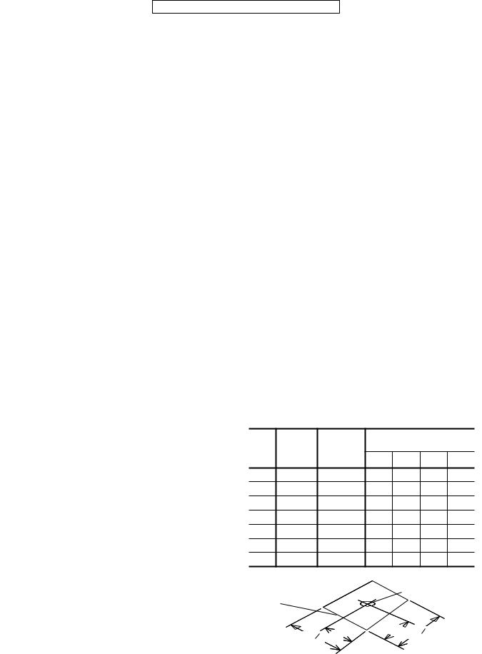
Refer to Table 2 for unit weights and to Figure 1 for approximate center of gravity.
TABLE 2 - UNITS WEIGHTS
|
SHIPPING |
OPERAT- |
CORNER WEIGHTS |
|
|||
UNIT |
ING |
|
(location, lbs.) |
|
|||
SIZE |
WEIGHT |
WEIGHT |
|
|
|
|
|
(lbs.) |
“A” |
“B” |
“C” |
“D” |
|||
|
(lbs.) |
||||||
|
|
||||||
018 |
318 |
313 |
86 |
76 |
73 |
83 |
|
024 |
324 |
319 |
88 |
77 |
75 |
85 |
|
030 |
333 |
328 |
85 |
81 |
82 |
86 |
|
036 |
338 |
333 |
91 |
80 |
78 |
88 |
|
042 |
347 |
342 |
94 |
83 |
80 |
91 |
|
048 |
368 |
363 |
92 |
88 |
92 |
97 |
|
060 |
376 |
371 |
105 |
100 |
84 |
87 |
|
|
|
“D” |
CENTER OF GRAVITY |
||||
|
|
|
|
||||
FRONT |
|
“A” |
|
“C” |
|
|
|
OF |
|
|
|
|
|
||
|
|
|
|
|
|
||
UNIT |
|
|
“B” |
|
|
|
|
|
|
|
|
|
|
||
|
49 1 |
26 |
|
47 |
1 |
|
|
|
|
|
4 |
|
|||
|
|
8 |
|
|
|
|
|
FIG. 1 - CENTER OF GRAVITY
2 |
Unitary Products Group |

CLEARANCES
All units require certain clearances for proper operation and service. Refer to Figure 3 for the clearances required for combustion, construction, servicing and proper unit operation.
WARNING: Do not permit overhanging structures or shrubs to obstruct the condenser air discharge outlet.
DUCT WORK
These units are adaptable to downflow use as well as rear supply and return air duct openings. To convert to downflow, use the following steps:
1.Remove the duct covers found in the bottom return and supply air duct openings. There are four (4) screws securing each duct cover (save these screws to use later).
2.Install the duct covers, removed in step one, to the rear supply and return air duct openings. Secure with the four (4) screws used in step one.
3.Seal the duct covers with silicone caulking.
Downflow units must have an L-shaped supply duct without any outlets or registers located directly below the supply outlet of the unit.
Duct work should be designed and sized according to the methods of the Air Conditioning Contractors of America (ACCA), as set forth in their Manual D.
A closed return duct system shall be used. This shall not preclude use of economizers or ventilation air intake. Flexible joints may be used in the supply and return duct work to minimize the transmission of noise.
CAUTION: When fastening duct work to the side duct flanges on the unit, insert the screws through the duct flanges only. DO NOT insert the screws through the casing. Outdoor duct work must be insulated and waterproofed.
NOTE: Be sure to note supply and return openings.
Refer to Figure 3 for information concerning rear and bottom supply and return air duct openings.
TABLE 3 - PHYSICAL DATA
035-16703-001-A-0202
FILTERS
Single phase units are shipped without a filter and is the responsibility of the installer to secure a filter in the return air ductwork or install a Filter/Frame Kit (1FF0114).
A filter rack and a filters are standard on three phase units.
Filters must always be used and must be kept clean. When filters become dirt laden, insufficient air will be delivered by the blower, decreasing your units efficiency and increasing operating costs and wear-and-tear on the unit and controls.
Filters should be checked monthly especially since this unit may be used for both heating and cooling.
CONDENSATE DRAIN
A condensate trap is required to be installed in the condensate drain. The plumbing must conform to local codes. Use a sealing compound on male pipe threads. Install the condensate drain line (34“ NPTF) to spill into an open drain.
SERVICE ACCESS
Access to all serviceable components is provided by the following removable panels:
•Blower service access
•Electrical/filter access
•Compressor service access
Refer to Figure 3 for location of these access panels and minimum clearance.
THERMOSTAT
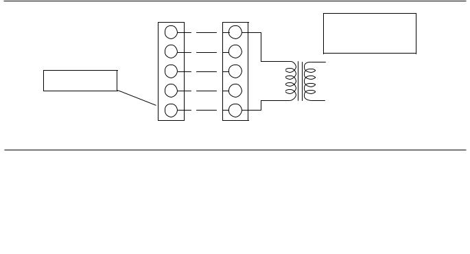
The room thermostat should be located on an inside wall approximately 56" above the floor where it will not be subject to drafts, sun exposure or heat from electrical fixtures or appliances. Follow manufacturer's instructions enclosed with the thermostat for general installation procedure. Four or five color coded insulated wires (minimum #18 AWG) should be used to connect thermostat to unit. See Figure 2.
|
MODELS |
|
|
|
DEB |
|
|
|
|
|
018 |
024 |
030 |
036 |
042 |
048 |
060 |
||
|
|
||||||||
EVAPORATOR |
CENTRIFUGAL BLOWER (Dia. x Wd. in.) |
9 X 6 |
10 X 8 |
10 X 8 |
10 x 8 |
11 X 10 |
11 x 10 |
11 x 10 |
|
BLOWER |
FAN MOTOR HP (Three Speed) |
12 |
12 |
12 |
34 |
34 |
34 |
1 |
|
EVAPORATOR |
ROWS DEEP |
2 |
2 |
2 |
2 |
2 |
2 |
3 |
|
FINS PER INCH |
13 |
15 |
15 |
15 |
15 |
13 |
16 |
||
COIL |
|||||||||
FACE AREA (Sq. Ft.) |
2.19 |
2.81 |
4.38 |
4.38 |
4.38 |
5.62 |
5.26 |
||
|
|||||||||
CONDENSER |
PROPELLER DIA. (in.) |
22 |
22 |
22 |
22 |
22 |
22 |
22 |
|
FAN MOTOR HP |
14 |
14 |
14 |
14 |
14 |
14 |
14 |
||
FAN |
|||||||||
NOM. CFM TOTAL |
1,800 |
2,200 |
2,400 |
2,400 |
2,400 |
2,800 |
2,800 |
||
|
|||||||||
CONDENSER |
ROWS DEEP |
1 |
1 |
1 |
1 |
1 |
1 |
1 |
|
FINS PER INCH |
18 |
16 |
20 |
18 |
16 |
13 |
20 |
||
COIL |
|||||||||
FACE AREA (Sq. Ft.) |
8.3 |
8.3 |
8.3 |
8.3 |
11.7 |
16.4 |
16.4 |
||
|
|||||||||
CHARGE |
REFRIGERANT 22 (lbs./oz.) |
3 / 4 |
3 / 5 |
3 / 13 |
3 / 10 |
4 / 7 |
5 / 15 |
5 / 15 |
|
FILTER |
FACE AREA (Sq. Ft. / Qty. / Size) |
|
|
2.14 / 2 / 14" x 22" |
|
|
|||
COMPRESSOR |
HERMETIC Type, (Qty. = 1) |
Recip |
Recip |
Recip |
Recip |
Recip |
Scroll |
Scroll |
|
Unitary Products Group |
3 |
035-16703-001-A-0202
POWER AND CONTROL WIRING
Field wiring to the unit must conform to provisions of the current N.E.C. ANSI/NFPA No. 70 or C.E.C. and/or local ordinances. The unit must be electrically grounded in accordance with local codes or, in their absence, with the N.E.C./C.E.C. Voltage tolerances which must be maintained at the compressor terminals during starting and running conditions are indicated on the unit Rating Plate and Table 3.
The wiring entering the cabinet must be provided with mechanical strain relief.
A fused or HACR breaker disconnect switch should be field provided for the unit. If any of the wire supplied with the unit must be replaced, replacement wire must be of the type shown on the wiring diagram.
Electrical line must be sized properly to carry the load. Each unit must be wired with a separate branch circuit fed directly from the meter panel and properly fused.
Refer to Figure 2 for typical field wiring and to the appropriate unit wiring diagram for control circuit and power wiring information.
COMPRESSORS
Units are shipped with compressor mountings factory-adjusted for shipping. CAUTION: Loosen compressor mounting bolts half turn before operating unit.
|
|
CONTROL WIRING |
|
THERMOSTAT |
UNIT TERMINAL STRIP |
||
** = Minimum wire size of 18 AWG |
R |
** |
R |
|
|
|
|
wire should be used for all field |
|
|
|
installed 24 volt wire. |
G |
|
G |
NOTE:
HEAT ANTICIPATOR SHOULD BE SET AT 0.25 AMPS FOR ALL MODELS.
PROGRAMMABLE
THERMOSTAT ONLY
* = Only required on units with supplemental electric heat.
YY
W * W
CC
24 VOLT TRANSFORMER |
CAUTION: Label all wires prior to disconnection when servicing controls. Wiring errors can cause improper and dangerous operation. Verify proper operation after servicing.
POWER WIRING
REFER TO ELECTRICAL DATA TABLES TO SIZE THE DISCONNECT SWITCH, WIRING & OVERCURRENT PROTECTION.
REFER TO ELECTRICAL DATA TABLES TO SIZE THE DISCONNECT SWITCH, WIRING & OVERCURRENT PROTECTION.
FIG. 2 - TYPICAL FIELD WIRING DIAGRAM
4 |
Unitary Products Group |
|
|
|
|
|
|
|
|
|
|
|
|
|
|
|
|
|
|
035-16703-001-A-0202 |
|||
TABLE 4 - ELECTRICAL DATA (BASIC UNIT) |
|
|
|
|
|
|
|
|
|
|
|
|
|
|
|
||||||
|
|
|
|
|
|
|
|
|
|
|
|
|
|
|
|
|
|
|
|
|
|
|
|
VOLTAGE |
|
|
|
COND. |
SUPPLY |
|
|
|
MAX. |
|
MAX. |
|
|
|
|
||||
MODEL |
POWER SUP- |
LIMITATIONS |
COMPRESSOR |
|
AIR |
|
MINIMUM |
FUSE |
|
HACR |
UNIT |
|
TRANSFORMER |
||||||||
|
FAN |
|
|
|
|||||||||||||||||
|
1 |
|
|
|
BLOWER |
|
CIRCUIT |
|
SIZE, |
BREAKER |
POWER |
|
|||||||||
DEB |
PLY |
|
|
|
|
|
|
MOTOR, |
|
|
|
|
SIZE (VA) |
||||||||
MIN. |
|
MAX. |
RLA |
LRA |
|
MOTOR, |
|
AMPACITY |
|
AMPS |
|
SIZE, |
FACTOR |
|
|
||||||
|
|
|
|
FLA |
FLA |
|
|
2 |
|
AMPS |
|
|
|
|
|||||||
|
|
|
|
|
|
|
|
|
|
|
|
|
|
|
|
|
|
||||
018 |
208/230-1-60 |
187 |
|
253 |
9.0 |
48.0 |
|
1.1 |
2.6 |
|
|
14.9 |
20 |
|
20 |
|
.96 |
|
40 |
||
024 |
208/230-1-60 |
187 |
|
253 |
11.5 |
60.0 |
|
1.1 |
2.6 |
|
|
18.1 |
25 |
|
25 |
|
.96 |
|
40 |
||
030 |
208/230-1-60 |
187 |
|
253 |
14.7 |
73.0 |
|
1.1 |
2.6 |
|
|
22.1 |
30 |
|
30 |
|
.96 |
|
40 |
||
036 |
208/230-1-60 |
187 |
|
253 |
17.3 |
94.0 |
|
1.1 |
3.5 |
|
|
26.2 |
35 |
|
35 |
|
.96 |
|
40 |
||
042 |
208/230-1-60 |
187 |
|
253 |
20.5 |
120.0 |
|
1.1 |
3.5 |
|
|
30.2 |
40 |
|
40 |
|
.96 |
|
40 |
||
048 |
208/230-1-60 |
187 |
|
253 |
24.4 |
140.0 |
|
1.3 |
4.0 |
|
|
35.8 |
45 |
|
45 |
|
.96 |
|
40 |
||
060 |
208/230-1-60 |
187 |
|
253 |
28.9 |
165.0 |
|
1.3 |
4.0 |
|
|
44.4 |
60 |
|
60 |
|
.96 |
|
40 |
||
|
|
|
|
|
|
|
|
|
|
|
|
|
|
|
|
|
|
|
|
|
|
036 |
208/230-3-60 |
187 |
|
253 |
10.9 |
78.0 |
|
1.1 |
3.5 |
|
|
18.2 |
25 |
|
25 |
|
.96 |
|
75 |
||
042 |
208/230-3-60 |
187 |
|
253 |
14.1 |
110.0 |
|
1.1 |
3.5 |
|
|
22.2 |
30 |
|
30 |
|
.96 |
|
75 |
||
048 |
208/230-3-60 |
187 |
|
253 |
14.1 |
105.0 |
|
0.7 |
4.0 |
|
|
22.3 |
30 |
|
30 |
|
.96 |
|
75 |
||
060 |
208/230-3-60 |
187 |
|
253 |
16.0 |
125.0 |
|
1.3 |
7.0 |
|
|
28.3 |
40 |
|
40 |
|
.96 |
|
75 |
||
|
|
|
|
|
|
|
|
|
|
|
|
|
|
|
|
|
|
|
|
|
|
036 |
460-3-60 |
414 |
|
504 |
5.8 |
40.0 |
|
0.6 |
1.8 |
|
|
9.6 |
15 |
|
15 |
|
.96 |
|
75 |
||
042 |
460-3-60 |
414 |
|
504 |
7.1 |
54.0 |
|
0.6 |
1.8 |
|
|
11.2 |
15 |
|
15 |
|
.96 |
|
75 |
||
048 |
460-3-60 |
414 |
|
504 |
7.1 |
55.0 |
|
0.6 |
2.0 |
|
|
11.5 |
15 |
|
15 |
|
.96 |
|
75 |
||
060 |
460-3-60 |
414 |
|
504 |
8.0 |
67.0 |
|
0.7 |
3.5 |
|
|
14.2 |
20 |
|
20 |
|
.96 |
|
75 |
||
|
|
|
|
|
|
|
|
|
|
|
|
|
|
|
|
|
|
|
|
|
|
036 |
575-3-60 |
518 |
|
630 |
4.5 |
32.0 |
|
0.4 |
1.5 |
|
|
7.6 |
15 |
|
15 |
|
.96 |
|
75 |
||
042 |
575-3-60 |
518 |
|
630 |
5.8 |
44.0 |
|
0.4 |
1.5 |
|
|
9.1 |
15 |
|
15 |
|
.96 |
|
75 |
||
048 |
575-3-60 |
518 |
|
630 |
5.6 |
44.0 |
|
0.6 |
1.6 |
|
|
9.3 |
15 |
|
15 |
|
.96 |
|
75 |
||
060 |
575-3-60 |
518 |
|
630 |
6.4 |
50.0 |
|
0.6 |
2.8 |
|
|
11.4 |
15 |
|
15 |
|
.96 |
|
75 |
||
1 = Rated in accordance with ARI Standard 110, utilization range “A”. |
2 = Dual element, time delay type. |
|
|
|
|
|
|
|
|
|
|||||||||||
|
|
|
|
|
|
|
|
|
|
|
|
* = KW listed is for 240 volts, use this table for 208 or 230 volts. |
|||||||||
|
|
|
|
|
|
|
|
|
|
|
|
|
|
NOMINAL VOLTAGE |
|
VOLTAGE |
|
KW CAP. MULTI- |
|||
|
|
|
|
|
|
|
|
|
|
ELECTRIC HEAT |
|
|
|
PLIER |
|||||||
|
|
|
|
|
|
|
|
|
|
|
|
|
|
|
|
|
|
||||
|
|
|
|
|
|
|
|
|
|
|
|
|
|
|
208 |
|
|
.75 |
|||
|
|
|
|
|
|
|
|
|
|
|
CORRECTION |
|
|
240 |
|
|
|
||||
|
|
|
|
|
|
|
|
|
|
|
|
|
|
230 |
|
|
.92 |
||||
|
|
|
|
|
|
|
|
|
|
|
|
FACTORS |
|
|
|
|
|
|
|
||
|
|
|
|
|
|
|
|
|
|
|
|
|
|
480 |
|
460 |
|
|
.92 |
||
|
|
|
|
|
|
|
|
|
|
|
|
|
|
|
|
|
|
||||
|
|
|
|
|
|
|
|
|
|
|
|
|
|
|
600 |
|
575 |
|
|
.92 |
|
Unitary Products Group |
5 |
035-16703-001-A-0202
TABLE 5 - ELECTRICAL DATA (COOLING / ELECTRIC HEAT)
DEB |
|
COMPRESSOR |
COND. |
SUPPLY |
ELECTRIC HEAT ACCESSORY |
|
MAX. |
MAX. |
||||||
|
|
|
|
|
|
|
|
MINIMUM |
||||||
|
POWER |
|
|
FAN |
AIR |
|
|
|
|
|
FUSE |
HACR2 |
||
MODEL |
SUPPLY |
|
|
MOTOR |
BLOWER |
|
STAGE |
|
|
|
CIRCUIT |
SIZE,1 |
BREAKER |
|
|
|
|
FLA |
MOTOR, |
|
|
|
TOTAL |
AMPACITY |
AMPS |
SIZE |
|||
|
|
RLA |
LRA |
FLA |
MODEL NO. |
|
KW |
|
|
|||||
|
|
|
|
|
AMPS |
|
|
|
||||||
|
|
|
|
|
|
|
|
|
|
|
|
|
||
|
|
|
|
|
|
|
|
|
|
|
|
|
|
|
018 |
208/230-1-60 |
9.0 |
48.0 |
1.1 |
2.6 |
2NH04500506 |
1 |
3.8/5.0 |
* |
18.1/20.8 |
25.8/29.3 |
30/30 |
30/30 |
|
2NH04500706 |
2 |
5.6/7.5 |
* |
27.1/31.3 |
37.1/42.3 |
40/45 |
40/45 |
|||||||
|
|
|
|
|
|
|||||||||
|
|
|
|
|
|
2NH04500506 |
1 |
3.8/5.0 |
* |
18.1/20.8 |
25.8/29.3 |
30/30 |
30/30 |
|
024 |
208/230-1-60 |
11.2 |
60.0 |
1.1 |
2.6 |
2NH04500706 |
2 |
5.6/7.5 |
* |
27.1/31.3 |
37.1/42.3 |
40/45 |
40/45 |
|
|
|
|
|
|
|
2NH04501006 |
2 |
7.5/10.0 |
* |
36.1/41.7 |
48.4/55.3 |
50/60 |
50/60 |
|
|
|
|
|
|
|
2NH04500506 |
1 |
3.8/5.0 |
* |
18.1/20.8 |
25.8/29.3 |
30/30 |
30/30 |
|
030 |
208/230-1-60 |
12.0 |
73.0 |
1.1 |
2.6 |
2NH04500706 |
2 |
5.6/7.5 |
* |
27.3/31.3 |
37.1/42.3 |
40/45 |
40/45 |
|
2NH04501006 |
2 |
7.5/10.0 |
* |
36.1/41.7 |
48.4/55.3 |
50/60 |
50/60 |
|||||||
|
|
|
|
|
|
|||||||||
|
|
|
|
|
|
2NH04501506 |
2 |
11.3/15.0 |
* |
54.2/62.5 |
71.0/81.4 |
80/90 |
80/90 |
|
036 |
208/230-1-60 |
17.3 |
94.0 |
1.1 |
3.5 |
2NH04501006 |
2 |
7.5/10.0 |
* |
36.1/41.7 |
49.5/56.5 |
50/60 |
50/60 |
|
2NH04501506 |
2 |
11.3/15.0 |
* |
54.2/62.5 |
72.1/82.5 |
80/90 |
80/90 |
|||||||
|
|
|
|
|
|
|||||||||
|
|
|
|
|
|
2NH04500506 |
1 |
3.8/5.0 |
* |
18.1/20.8 |
30.2/30.4 |
40/40 |
40/40 |
|
042 |
208/230-1-60 |
20.5 |
120.0 |
1.1 |
3.5 |
2NH04500706 |
2 |
5.6/7.5 |
* |
27.1/31.3 |
38.2/43.4 |
50/50 |
50/50 |
|
2NH04501006 |
2 |
7.5/10.0 |
* |
36.1/41.7 |
49.5/56.5 |
50/60 |
50/60 |
|||||||
|
|
|
|
|
|
|||||||||
|
|
|
|
|
|
2NH04501506 |
2 |
11.3/15.0 |
* |
54.2/62.5 |
72.1/82.5 |
80/90 |
80/90 |
|
|
|
|
|
|
|
2NH04501006 |
2 |
7.5/10.0 |
* |
36.1/41.7 |
50.1/57.1 |
60/60 |
60/60 |
|
048 |
208/230-1-60 |
24.4 |
140.0 |
1.3 |
4.0 |
2NH04501506 |
2 |
11.3/15.0 |
* |
54.2/62.5 |
72.1/83.1 |
80/90 |
80/90 |
|
2NH04502006 |
2 |
15.0/20.0 |
* |
72.2/83.3 |
95.3/109.2 |
100/110 |
100/110 |
|||||||
|
|
|
|
|
|
|||||||||
|
|
|
|
|
|
2NH04502506 |
2 |
18.8/25.0 |
* |
90.3/104.2 |
117.8/135.2 |
125/150 |
125/150 |
|
|
|
|
|
|
|
2NH04501006 |
2 |
7.5/10.0 |
* |
36.1/41.7 |
53.9/60.8 |
70/70 |
70/70 |
|
060 |
208/230-1-60 |
28.9 |
165.0 |
1.3 |
7.0 |
2NH04501506 |
2 |
11.3/15.0 |
* |
54.2/62.5 |
76.5/86.9 |
80/90 |
80/90 |
|
2NH04502006 |
2 |
15.0/20.0 |
* |
72.2/83.3 |
99.0/112.9 |
100/125 |
100/125 |
|||||||
|
|
|
|
|
|
|||||||||
|
|
|
|
|
|
2NH04502506 |
2 |
18.8/25.0 |
* |
90.3/104.2 |
121.6/139.0 |
125/150 |
125/150 |
|
|
|
|
|
|
|
|
|
|
|
|
|
|
|
|
036 |
208/230-3-60 |
10.9 |
78.0 |
1.1 |
3.5 |
2NH04501025 |
1 |
7.5/10.0 |
* |
20.8/24.1 |
30.4/34.4 |
35/35 |
35/35 |
|
2NH04501525 |
1 |
11.3/15.0 |
* |
31.3/36.1 |
43.5/49.5 |
45/50 |
45/50 |
|||||||
|
|
|
|
|
|
|||||||||
042 |
208/230-3-60 |
14.1 |
110.0 |
1.1 |
3.5 |
2NH04501025 |
1 |
7.5/10.0 |
* |
20.8/24.1 |
30.4/34.4 |
35/35 |
35/35 |
|
2NH04501525 |
1 |
11.3/15.0 |
* |
31.3/36.1 |
43.5/49.5 |
45/50 |
45/50 |
|||||||
|
|
|
|
|
|
|||||||||
|
|
|
|
|
|
2NH04501025 |
1 |
7.5/10.0 |
* |
20.8/24.1 |
31.1/35.1 |
35/40 |
35/40 |
|
048 |
208/230-3-60 |
14.1 |
105.0 |
0.7 |
4.0 |
2NH04501525 |
1 |
11.3/15.0 |
* |
31.3/36.1 |
44.1/50.1 |
45/60 |
45/60 |
|
2NH04502025 |
2 |
15.0/20.0 |
* |
41.7/48.1 |
57.1/65.1 |
60/70 |
60/70 |
|||||||
|
|
|
|
|
|
|||||||||
|
|
|
|
|
|
2NH04502525 |
2 |
18.8/25.0 |
* |
52.1/60.1 |
70.2/80.2 |
80/90 |
80/90 |
|
|
|
|
|
|
|
2NH04501025 |
1 |
7.5/10.0 |
* |
20.8/24.1 |
34.8/38.8 |
40/40 |
40/40 |
|
060 |
208/230-3-60 |
16.0 |
125.0 |
1.3 |
7.0 |
2NH04501525 |
1 |
11.3/15.0 |
* |
31.3/36.1 |
47.8/53.9 |
50/60 |
50/60 |
|
2NH04502025 |
2 |
15.0/20.0 |
* |
41.7/48.1 |
60.9/68.9 |
70/70 |
70/70 |
|||||||
|
|
|
|
|
|
|||||||||
|
|
|
|
|
|
2NH04502525 |
2 |
18.8/25.0 |
* |
52.1/60.1 |
73.9/83.9 |
80/90 |
80/90 |
|
036 |
460-3-60 |
5.8 |
40.0 |
0.6 |
1.8 |
2NH04501046 |
1 |
10.0 ** |
12.0 |
17.3 |
20 |
20 |
||
2NH04501546 |
1 |
15.0 ** |
18.0 |
24.8 |
25 |
25 |
||||||||
|
|
|
|
|
|
|||||||||
042 |
460-3-60 |
7.1 |
54.0 |
0.6 |
1.8 |
2NH04501046 |
1 |
10.0 ** |
12.0 |
17.3 |
20 |
20 |
||
2NH04501546 |
1 |
15.0 ** |
18.0 |
24.8 |
25 |
25 |
||||||||
|
|
|
|
|
|
|||||||||
|
|
|
|
|
|
2NH04501046 |
1 |
10.0 ** |
12.0 |
17.5 |
20 |
20 |
||
048 |
460-3-60 |
7.1 |
55.0 |
0.6 |
2.0 |
2NH04501546 |
1 |
15.0 ** |
18.0 |
25.1 |
30 |
30 |
||
2NH04502046 |
2 |
20.0 ** |
24.1 |
32.6 |
35 |
35 |
||||||||
|
|
|
|
|
|
|||||||||
|
|
|
|
|
|
2NH04502546 |
2 |
25.0 ** |
30.1 |
40.1 |
45 |
45 |
||
|
|
|
|
|
|
2NH04501046 |
1 |
10.0 ** |
12.0 |
19.4 |
20 |
20 |
||
060 |
460-3-60 |
8.0 |
67.0 |
0.7 |
3.5 |
2NH04501546 |
1 |
15.0 ** |
18.0 |
26.9 |
30 |
30 |
||
2NH04502046 |
2 |
20.0 ** |
24.1 |
34.4 |
35 |
35 |
||||||||
|
|
|
|
|
|
|||||||||
|
|
|
|
|
|
2NH04502546 |
2 |
25.0 ** |
30.1 |
42.0 |
45 |
45 |
||
|
|
|
|
|
|
|
|
|
|
|
|
|
||
036 |
575-3-60 |
4.5 |
32.0 |
0.4 |
1.5 |
2NH04501058 |
1 |
10.0 *** |
9.6 |
13.9 |
15 |
15 |
||
2NH04501558 |
1 |
15.0 *** |
14.4 |
19.9 |
20 |
20 |
||||||||
|
|
|
|
|
|
|||||||||
042 |
575-3-60 |
5.8 |
44.0 |
0.4 |
1.5 |
2NH04501058 |
1 |
10.0 *** |
9.6 |
13.9 |
15 |
15 |
||
2NH04501558 |
1 |
15.0 *** |
14.4 |
19.9 |
20 |
20 |
||||||||
|
|
|
|
|
|
|||||||||
|
|
|
|
|
|
2NH04501058 |
1 |
10.0 *** |
9.6 |
14.0 |
15 |
15 |
||
048 |
575-3-60 |
5.6 |
44.0 |
0.6 |
1.6 |
2NH04501558 |
1 |
15.0 *** |
14.4 |
20.0 |
25 |
25 |
||
2NH04502058 |
2 |
20.0 *** |
19.2 |
26.1 |
30 |
30 |
||||||||
|
|
|
|
|
|
|||||||||
|
|
|
|
|
|
2NH04502558 |
2 |
25.0 *** |
24.1 |
32.1 |
35 |
35 |
||
|
|
|
|
|
|
2NH04501058 |
1 |
10.0 *** |
9.6 |
15.5 |
20 |
20 |
||
060 |
575-3-60 |
6.4 |
50.0 |
0.6 |
2.8 |
2NH04501558 |
1 |
15.0 *** |
14.4 |
21.5 |
25 |
25 |
||
2NH04502058 |
2 |
20.0 *** |
19.2 |
27.6 |
30 |
30 |
||||||||
|
|
|
|
|
|
|||||||||
|
|
|
|
|
|
2NH04502558 |
2 |
25.0 *** |
24.1 |
33.6 |
35 |
35 |
||
1= Dual element, time delay type.
2= Standard circuit breakers may be used in Canada and on applications over 60 amps where the heaters are separately fused.
* = KW listed is for 240 volts, use table on previous page for 208 or 230 volts.
**= KW listed is for 480 volts, use table on previous page for 460 volts.
***= KW listed is for 600 volts, use table on previous page for 575 volts.
6 |
Unitary Products Group |
 Loading...