


CONTENTS
SAFETY INFORMATION
FOR YOUR SAFETY . . . . . . . . . . . . . . . . . . . . . . . 2
SYSTEM OPERATION . . . . . . . . . . . . . . . . . . 2
THERMOSTATS . . . . . . . . . . . . . . . . . . . . . . . . . . 2 INTERMITTENT IGNITION DEVICE . . . . . . . . . . 2 OPERATING INSTRUCTIONS . . . . . . . . . . . . . . . 3 TO SHUT DOWN THE FURNACE: . . . . . . . . . . . 3 TO LIGHT THE FURNACE: . . . . . . . . . . . . . . . . . . 3 VENT SAFETY SYSTEM: . . . . . . . . . . . . . . . . . . . 3 100% SHUT OFF: . . . . . . . . . . . . . . . . . . . . . . . . . 3
EXPLAIN UNIT FUNCTION . . . . . . . . . . . . . . 4
GENERAL MAINTENANCE . . . . . . . . . . . . . . 4
HEATING SYSTEM INSPECTION . . . . . . . . . . . . 4 BURNER AND PILOT CHECK . . . . . . . . . . . . . . . 5 CLEANING BURNERS . . . . . . . . . . . . . . . . . . . . . 5 CLEANING FLUE PASSAGES AND
HEATING ELEMENTS . . . . . . . . . . . . . . . . . . . . . . 5 AIR FILTERS . . . . . . . . . . . . . . . . . . . . . . . . . . . . 5 BLOWER ASSEMBLY . . . . . . . . . . . . . . . . . . . . . . 6 MOTORS . . . . . . . . . . . . . . . . . . . . . . . . . . . . . . . 6 CONDENSER COIL. . . . . . . . . . . . . . . . . . . . . . . . 7 REGISTERS . . . . . . . . . . . . . . . . . . . . . . . . . . . . . 7
TROUBLESHOOTING . . . . . . . . . . . . . . . . . . 7
BEFORE CALLING A SERVICE
TECHNICIAN: . . . . . . . . . . . . . . . . . . . . . . . . . . . . 7
REPLACEMENT PARTS . . . . . . . . . . . . . . . . 8
®
USER’S, MAINTENANCE and
SERVICE INFORMATION
MANUAL
S I N G L E PA C K A G E
A I R C O N D I T I O N E R
G A S / E L E C T R I C
The manufacturer recommends that the “User” read all sections of this manual and keep the manual for future reference.
FIRE OR EXPLOSION HAZARD
Failure to follow safety warnings exactly could result in serious injury, death, or property damage.
-Do not store or use gasoline or other flammable vapors and liquids in the vicinity of this or any other appliance.
-WHAT TO DO IF YOU SMELL GAS:
•Do not try to light any appliance.
•Do not touch any electrical switch; do not use any phone in your building.
•Leave the building immediately.
•Immediately call your gas supplier from a neighbor’s phone. Follow the gas supplier’s instructions.
•If you cannot reach your gas supplier, call the fire department.
-Installation and service must be performed by a qualified installer, service agency or the gas supplier.
035-18843-000-A-0402
035-18843-000-A-0402
SAFETY INFORMATION
FOR YOUR SAFETY
•Make sure that the furnace area is clear and free of combustible materials, gasoline and other flammable vapors and liquids.
•Be sure the furnace is free and clear of insulating material. Examine the furnace area after installation of the furnace or the installation of additional insulation. Some types of insulation are combustible.
•For proper operation of this furnace, air for combustion and ventilation is required. Make sure that these openings are not obstructed.
•For lighting or shutting down this furnace, refer to the lighting instructions provided adjacent to the burners and also located in this manual.
•A blocked vent roll-out switch is provided in the burner compartment. This switch is a manual reset. If the furnace fails to operate, contact a qualified service technician.
•Should the gas supply fail to shut off or if overheating occurs, shut off the gas valve to the furnace before shutting off the electrical supply. Then call a qualified service technician.
•Do not use this furnace if any part has been under water. A flood-damaged furnace is extremely dangerous. Attempts to use the furnace can result in fire or explosion. A qualified service technician should be contacted to inspect the furnace and to replace all gas controls, control system parts, electrical parts that have been wet or the furnace if deemed necessary.
•Determine the integrity of the installation regarding the flue gas vent, the return and supply air duct. Confirm the equipment is well supported and there are no signs of deterioration. The manufacturer recommends that main burner, ignition device and controls are inspected by a qualified service technician before each heating season.
SYSTEM OPERATION
THERMOSTATS
Set your thermostat for either heating or cooling then set it for the desired temperature. DO NOT MOVE THE THERMOSTAT RAPIDLY ON AND OFF, OR BACK AND FORTH FROM HEAT TO COOL. THIS COULD DAMAGE YOUR EQUIPMENT.
Always allow at least 5 minutes between changes. Find the temperature that is most comfortable to you, and then LEAVE YOUR THERMOSTAT ALONE. (Exception is for night or vacation “set back” to conserve energy).
Manually moving the thermostat up or down will not speed up temperature changes in your rooms. This only causes the thermostat switch to function at your command rather than responding to room temperature.
Heat generated by devices other than the furnace may interfere with thermostat performance. Therefore, lamps, radios, television sets, etc. should not be placed near the thermostat.
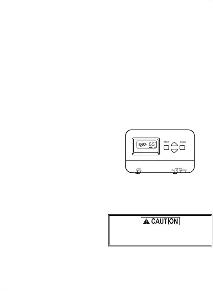
FIGURE 1: TYPICAL THERMOSTAT
INTERMITTENT IGNITION DEVICE
Your unit is equipped with a cycling pilot burner. It has a Pilot Relight control designed to automatically light the pilot burner each time the thermostat “calls” for heat.
This furnace is equipped with an intermittent pilot and automatic re-ignition system. Do Not attempt to manually relight the pilot. Personal injury could result.
When the thermostat calls for heat, pilot gas is supplied and at the same time, sparking occurs to light the pilot gas. With the pilot lit, the flame sensor rod closes a circuit to the ignitor control which then opens the gas valve to admit main burner gas.
2 |
Unitary Products Group |

035-18843-000-A-0402
When the room thermostat is satisfied, the electrical circuit to the gas valve is opened, closing off both main burner and pilot gas simultaneously. If the pilot burner should fail to light, contact your heating contractor or gas utility for service to insure that proper operating conditions are restored.
INPUT
The correct heat capacity of the furnace is regulated by the burner orifices and the gas pressure. The proper orifices are furnished but the gas pressure regulator must be adjusted by the installer or gas utility service technician.
OPERATING INSTRUCTIONS
TO SHUT DOWN THE FURNACE:
1.Close the main gas shutoff valve(s).
2.Turn off the electric power supply.
TO LIGHT THE FURNACE:
1.Do not attempt to light manually.
2.Open the main gas shutoff valve(s).
3.Adjust the set point of the room thermostat above the temperature in the space.
4.Turn on the electric power supply.
5.The draft fan will operate. After an adequate purge time, the electric spark igniter will light the burners.
6.The burners will extinguish and relight automatically upon the demand of the room thermostat.
FIGURE 2: TYPICAL INSTALLATION
VENT SAFETY SYSTEM:
This gas furnace is equipped with an automatic reset high temperature sensor or rollout switch which in the unlikely event of a sustained main burner flame rollout will shut off the flow of gas by closing the main gas valve. The ignition modules will also be disabled, preventing the flow of gas to the valves. The switch is located inside the gas heat access panel above the burner inlet. Flame rollout can be caused by blockage of the power vent system, improper gas pressure or adjustment. If this event occurs the furnace will not operate properly, gas supply to the furnace should be shut off and no attempt should be made to place the furnace in operation. The system should be inspected by a qualified service technician. Refer to Figure 2 for a typical installation.
100% SHUT OFF:
The ignition modules are designed for 100% shut-off. If the furnace fails to ignite within 85 seconds after a call for heat, the flow of gas (including pilot) will be shut off and the ignition module will lock out. The module can be reset by:
A.Turning the system switch on the room thermostat
to the “OFF” position and back to the “HEAT” position.
B.Decreasing the set point of the room thermostat below the temperature in the conditioned space and returning it to its original setting.
C.Opening and closing the unit's main disconnect switch.
Unitary Products Group |
3 |
 Loading...