


<<Contents>> <<Index>>
General
Specifications
MODEL UT520
Digital Indicating Controller
GS 05D01C02-02E
■ General |
UT520 |
Model UT520 Digital Indicating Controller is an intelligent, micro-processor based digital indicating controller with powerful control capability and the user-friendly large numerical display. The UT520 features as standard many functions which are necessary for various control applications, and all of these functions such as control function, control computation function, signal computation function, etc. can be configured by using the keys on the front panel. The instrument has eight types of control strategies and also an overshoot suppressing function "SUPER" and a hunting suppressing function "SUPER 2" as well as an auto-tuning function built in as standard. Panel size is small, 48 mm (width) × 96 mm (height), and designed for saving space.
UT520E
“E” indicates the model with expanded functions.
■ Main Features
•High resolution display of 5 digits. Since LEDs of 12 mm height are used for displaying measured values, the display is clearly read.
•The front panel size is 48 mm (width) × 96 mm (height) and the depth is 100 mm, designed for saving space.
•Eight types of control function, including single-loop control, cascade control, loop control with PV autoselector, and loop control with PV-hold function, enabling the operator to start control operation immediately after simply entering the settings.
•Parameter can be easily set using a personal computer. ("Parameter setting tool (model LL100)" sold separately is required.)
•Universal input and output enables users to set or change freely the type of measured inputs, measurement input range, type of control output, etc. from the front panel.
•Contact inputs (up to 4 points) and contact outputs (up to
4 points)Note can be employed and functions can be assigned to each contact (The maximum number of points varies depending on the specification code.)
Note: See the Hardware Specifications and Contact Outputs described later.
• Various communication function are provided. Communication is possible with personal computer, programable logic controller, and other controllers.
■ Functional Specifications
● Control Functions
UT Mode
The following types of basic control structure can be set as the UT mode by the user.
Single-loop control (UT mode 1):
The most simple and basic control function. Cascade primary-loop control (UT mode 2):
Output tracking function and cascade control logic are provided. Suitable for primary-loop cascade control.
Cascade secondary-loop control (UT mode 3):
Setpoint output and the cascade control logic are provided. Suitable for secondary-loop cascade control.
Cascade control (UT mode 4):
Dual control function for cascade control is available in a single instrument.
Loop control for back-up (UT mode 5):
Output tracking function is provided to back up another control instrument. The local and remote control outputs are switched by a contact input.
Loop control with PV switching (UT mode 6):
Two measured inputs are switched for control depending on the status of contact input or measured input.
Loop control with PV auto-selector (UT mode 7): Two measured inputs are automatically selected for control with a high, low, or average, or temperature-difference value selector.
Loop control with PV-hold function (UT mode 8): This control holds a PV input and a control output if an external sensor is switched.
● Control Computation Functions
In each UT mode, the following control computation functions can be selected.
Continuous PID control, Time-proportional PID control, and Relay ON/OFF control.
Target setpoint and PID parameters:
Maximum eight sets of target setpoint and PID parameters can be set. These eight sets can be set for both the main and slave loops in cascade control.
Zone PID selection:
Dividing measuring range into maximum 7 zones by maximum 6-reference points, PID parameter set switching in up to 7 measured input zones.
Auto-tuning:
Available as standard. Possible to activate auto-tuning for both main and slave loops for cascade control.
GS 05D01C02-02E © Copyright Feb. 2000 (YK)
1st Edition Mar. 2000 (YG)

<<Contents>> <<Index>> |
2 |
|
|
Preset output function:
When the instrument is in STOP mode, measured input is burnt-out, or an abnormality is found in an input circuit, a preset value is output as a control output.
"SUPER" function:
Overshoots generated by abrupt changes in the target setpoint or by disturbances can be suppressed.
"SUPER 2" function:
The function stabilizes the state of control that is unstable due to hunting, etc. without requiring any change in PID constants, when the load and/or gain varies greatly, or when there is a difference between the characteris-
|
tics of temperature zones. |
Control cycle time |
|
|
Each cycle time can be selected under the |
|
following conditions.: |
50 ms: |
Available for model code UT520-00, when |
|
UT mode is set to Single-loop control and |
|
the following functions are not used: |
|
"SUPER" function, "SUPER 2" function, |
|
PV input computation, setpoint rate-of- |
|
change limiter, MV output rate-of-change |
|
limiter, deviation alarm, sensor grounding |
|
alarm, fault diagnosis alarm, and FAIL |
|
output. |
100 ms: |
Available when UT mode is not cascade |
|
control. |
200 ms: |
Available when UT mode is cascade control. |
(Set value on shipped from the factory: 200 ms)
Operation Mode Switching
(Note: Communication enables all the following mode switching to be executed.)
AUTO/MANUAL switching:
Bumpless switching between automatic operation mode and manual control mode is available by using the front keys or contact input. The contact input has priority over front key input or switching by communication. The contact input is invalid for Cascade secondary-loop control or Cascade control.
RUN/STOP switching:
Switching by contact input (bumpless for switching from STOP to RUN). The contact input has priority over switching by communication. In RUN mode, control computation is activated. In STOP mode, control computation ceases and a preset value is output as a control output while other functions operate normally.
REMOTE/LOCAL switching:
Switching between remote setpoint and local setpoint by instrument operation or contact input. The contact input has priority over instrument operation or switching by communication. For remote to local switching, either bumpless tracking (employing the remote setpoint on switching as the local setpoint) or without tracking (directly switching the local setpoint) can be specified.
CASCADE/AUTO/MANUAL switching:
Switching by instrument operation or contact input. The contact input has priority over instrument operation or switching by communication. Valid for Cascade second-
ary-loop control or Cascade control. Output tracking ON/OFF switching:
Provided for Cascade primary-loop control or Loop control for backup. External tracking signal and internal control output are switched by the contact input. The contact input has priority over the switching by communication.
Control Parameters Setting Range
Proportional band: 0.1 to 999.9%
Integral time: 1 to 6,000 s, or OFF (for Manual reset) Derivative time: 1 to 6,000 s, or OFF
ON/OFF control hysteresis:
0.0 to 100.0% of measured input range width Preset output: -5.0 to 105.0% of the output (0 mA or less
cannot be output) Output limiter:
Setting range: -5.0 to 105.0% for both high and low limits
However, "low limit setpoint < high limit setpoint" must be satisfied.
Shutdown function:
When manual control is carried out with 4 to 20 mA output, control output can be output down to about 0 mA (shutdown is specified for -5.0% or less).
Rate-of-change limiter for output: OFF or 0.1 to 100.0%/s
● Configuration of Input/Output Signal
Measured Input Computations
Input processing, Square root extraction (voltage input only, Input low cut 0.0 to 5.0%), Ten-segment linearizer function, Ten-Segment bias, Bias addition (-100.0 to 100.0%), and First order lag filter (OFF, time constant 1 to 120 s)
Auxiliary Input Computations
(Applied to remote setting input only)
Input processing, Square root extraction (Input low cut 0.0 to 5.0%), Bias addition (-100.0 to 100.0%), Ratio multiplication (0.001 to 9.999), and First order lag filter (OFF, time constant 1 to 120 s)
● Alarm Functions
Alarm types:
PV high limit, PV low limit, Deviation high limit, Deviation low limit, Deenergized on deviation high limit, Deenergized on deviation low limit, Deviation high and low limits, High and low limits within deviation, Deenergized on PV high limit, Deenergized on PV low limit, SP high limit, SP low limit, Output high limit, Output low limit.
Alarm setting range:
PV/SP alarm: -100 to 100% of measured input range
Deviation alarm: -100 to 100% of measured input range span
Output alarm: -5.0 to 105.0% of output value Alarm hysteresis: 0.0 to 100.0% of measured input range span
Delay timer:
0.00 to 99.59 (minute, second)
An alarm is output when the delay timer expires after the alarm setpoint is reached. Setting for each alarm is possible.
All Rights Reserved. Copyright © 2000, Yokogawa M&C Corporation |
GS 05D01C02-02E 1st Edition Mar. 31, 2000-00 |
<<Contents>> <<Index>> |
3 |
|
|
Stand-by action:
Stand-by action can be set to make PV/ deviation alarm OFF during start-up or after SP change until SP reaches the normal region.
Timer function (stabilization of control status notification event) (Alarm 1 only):
This function sets the alarm 1 output to ON when a preset time (timer setting) elapses after a PV has reached to the control target setpoint hysteresis band to notify that processing has completed. Restarted in RUN/STOP or SP switching.
Other alarm actions:
Sensor grounding alarm: Detects sensor deterioration and outputs an alarm.
Fault-diagnosis alarm: For input burnout, A/D conversion error, or thermocouple reference junction compensation error.
FAIL output: Abnormality in software or hardware. Number of alarm settings: 4
The alarm status can be read via communication in addition to output as the above alarm output.
Alarm output points (see also the item "Contact Outputs") Number of contact (relay) outputs: 3 (standard) or 4 (if a control output relay is used for the alarm 4 output relay.)
Any of PV alarm, deviation alarm, SP alarm, output alarm, Fault-diagnosis alarm, sensor grounding alarm and FAIL output can be assigned to contacts for the above number of outputs. However, the timer delay alarm can be assigned to the alarm 1 output only. Also, the alarm 4 only can be assigned to the control output relay (if a relay is not used for control output).
● Display and Operation Functions
PV Display
PV is displayed on the 5-digit display. PV1 and PV2 are displayed by switching them in cascade control. The number of display digits is 4 or 5. For thermocouple or RTD, data below the decimal point can be set not to display. The display range is -19999 to 30000 and the display span is 30000 or less. [520.00 appearing in the product photograph on page 1 cannot actually be displayed.]
Setpoint Display
A parameter name is displayed in the 3-digit display and data in the 5-digit display. There are four kinds of displays : operating display, operating parameter setting display, setup parameter setting display and SELECT display.
Operating display:
Data necessary for operations, such as setpoint or control output, are displayed depending on the UT mode.
Operating parameters setting display:
The Operating parameters, which are mainly changed during operation, such as PID constant, are displayed.
Setup parameters setting display:
The Setup parameters to configure the functions of the instrument before starting operation are displayed.
UT model is to be set in this display. SELECT display:
Up to five displays which are frequently accessed can be selected from the Operating parameters setting display and Setup parameters setting display to be displayed in the SELECT display.
Status Lamps
Alarm indicating lamp:
Four lamps, AL1, AL2, AL3, and AL4 Operation mode indicating lamp:
REM (remote operation), MAN (manual mode operation), CAS (cascade operation), and LP2 (cascade secondary-loop control)
Operation Keys
n, , keys: Increases or decreases setpoints and other parameters displayed in the setpoint display.
SET/ENT key: Used for setting or change set data, switching the displayed contents, and switching operation modes except for A/M.
A/M key: Operation mode switching (Auto/Man)
Security Function
Key-lock by parameters setting and prohibiting operation are available by a password
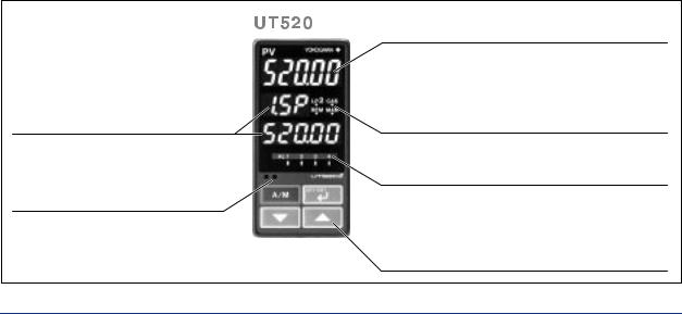
Data display unit
Displays setpoints (SP), output values, valve opening,or parameters.
Communication port for light loader
Parameters are set via communication from a personal computer.
Measured value (PV) display unit
Displays PV and error codes when errors are detected.
Status lamps
Cascade operation(CAS) and remote operation(REM) Manual operation (MAN)
Lit for secondary parameter indication (LP2)
Alarm indicating lamps
Displays alarms
(AL1, AL2, AL3, or AL4).
Operation keys
Increase/decrease of the setting data (n, ,) Screen switching/parameter selection/entry of set data (SET/ENT)
Auto/manual operation mode selection (A/M)
All Rights Reserved. Copyright © 2000, Yokogawa M&C Corporation |
GS 05D01C02-02E 1st Edition Mar. 31, 2000-00 |
<<Contents>> <<Index>> |
4 |
● Communication Functions
(For optional function code h7 only)
This controller has four types of communication protocol with one communication interface. Communication is possible with personal computer, programmable logic controller, and other controllers.
Communication Protocol
Computer link communication:
Communication protocol with a personal computer
Ladder communication:
Communication protocol with the ladder program on some programmable logic controllers.
Coordinated operation:
Protocol for coordinated operation with more than one GREEN SERIES controller. The UT520 controller can be connected as a master or slave station.
MODBUS communication:
Communication protocol with a personal computer, or PLC.
RS-485 Communication Interface
The RS485 communication interface (conforms to EIA RS485) can be used for personal computer link, ladder communication, MODBUS communication or for coordinated operation.
Maximum number of connectable controllers: GREEN SERIES controller 31
Maximum communication distance: 1200 m Communication method:
Two-wire half-duplex or four-wire halfduplex, start-stop synchronization, and nonprocedural
Communication rate:
600, 1200, 2400, 4800, or 9600 bps
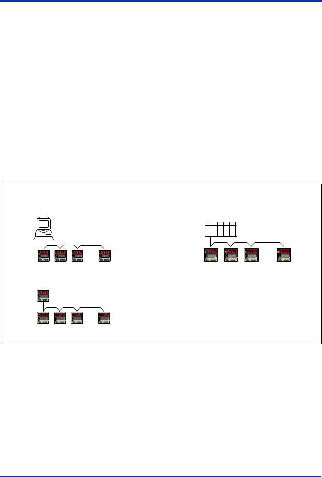
Examples of Communication System Configuration Diagram |
|
|
|
|
|
(1) Personal computer link communication/ |
(2) Ladder communication |
|
|||
MODBUS communication |
|
|
|
|
|
Personal computer |
|
MELSEC-A |
|
|
|
|
|
|
|
|
|
|
|
|
|
Programmable logic controller |
|
|
|
PV |
PV |
PV |
PV |
UT550, UT520 |
|
UT550, UT520 |
|
||
Digital indicating controller |
|
Digital indicating controller |
|
||
(3) Coordinated operation |
|
|
|
|
|
UP750, UP550 Program controller |
|
|
|
|
|
or |
|
|
|
|
|
UT750, UT550, UT520 |
Digital indicating controller |
|
|
|
|
UT550, UT520 |
|
|
|
|
|
Digital indicating controller |
|
|
|
|
|
All Rights Reserved. Copyright © 2000, Yokogawa M&C Corporation |
GS 05D01C02-02E 1st Edition Mar. 31, 2000-00 |

<<Contents>> <<Index>> |
5 |
■ Hardware Specifications
● Input/Output Signal Specifications
Measured Input Signal
Number of input points: 1
Type of input, measurement range, and measurement accuracy:
The type of input and measurement range can be specified from the input range code shown in the table below.
Sampling period: 50, 100, 200 or 500 ms (selectable) Burnout detection:
Activated for thermocouple (TC) input, RTD input, or standard signal of 0.4 to 2 V DC or 1 to 5 V DC.
Possible to specify a travel of upscale, downscale, or off.
For standard signal input (see the table below), set to burn out at 0.1 V or less.
Input bias current: 0.05 µA (for TC or RTD b-terminal) Measurement current(RTD): about 0.13 mA
Input resistance:
1 MΩ or more for TC or mV input About 1 MΩ for DC voltage input
Allowable signal source resistance:
250 Ω or less for TC or mV input Signal source resistance effect 0.1 µV/ Ω or less
2 kΩ or less for DC voltage input Signal source resistance effect Approx. 0.01%/100 Ω
Allowable leadwire resistance (for RTD input): Maximum 150 Ω/one wire (Lead resistances of three wires must be equal.)
However, it must be 10 Ω/one wire for the range of -150.0 to 150.0°C.
Effect of wiring resistance: ±0.1°C/10 Ω Allowable input voltage:
±10 V DC for TC/mV/RTD input ±20 V DC for DC voltage input
Noise rejection ratio:
Normal mode 40 dB (50/60 Hz) or more Common mode 120 dB (50/60 Hz) or more
Reference junction compensation error:
±1.0°C (15 to 35°C), ±1.5°C (0 to 15°C and 35 to 50°C)
Applicable standards: JIS, IEC, and DIN (ITS-90) for TC and RTD
Input type |
Input range |
Instrument |
|
Instrument |
Instrument accuracy*1 |
||
code |
range (°C) |
|
range (°F) |
||||
|
|
|
|
||||
Unspecified (When shipped from the factory) |
OFF |
Set the data item PV input type “IN 1” to the OFF option to leave the PV input type undefined. |
|||||
|
|
|
|
|
|
|
|
Thermocouple |
K |
1 |
-270.0 to 1370.0 C |
-450.0 to 2500.0°F |
±0.1% ±1 digit of instrument range at 0°C or more |
||
° |
±0.2% ±1 digit of instrument range at less than 0°C |
||||||
|
|
2 |
-270.0 to 1000.0°C |
-450.0 to 2300.0°F |
|||
|
|
• However, ±2% ±1 digit of instrument range for type K |
|||||
|
|
3 |
-200.0 to 500.0°C |
-200.0 to 1000.0°F |
at temperatures less than -200°C. |
||
|
|
|
|
|
|
• However, ±1% ± 1 digit of instrument range for type T |
|
|
J |
4 |
-200.0 to 1200.0°C |
-300.0 to 2300.0°F |
|||
|
|
|
|
|
|
|
at temperatures less than -200°C. |
|
T |
5 |
-270.0 to 400.0°C |
-450.0 to 750.0°F |
|||
|
|
||||||
|
|
6 |
0.0 to 400.0°C |
|
-200.0 to 750.0°F |
|
|
|
B |
7 |
0.0 to 1800.0°C |
32 to 3300°F |
±0.15% ±1 digit of instrument range at 400°C or more |
||
|
|
|
|
|
|
±5% ±1 digit of instrument range at less than 400°C |
|
|
|
|
|
|
|
|
|
|
S |
8 |
0.0 to 1700.0°C |
32 to 3100°F |
±0.15% ± 1 digit of instrument range |
||
|
R |
9 |
0.0 to 1700.0°C |
32 to 3100°F |
|
||
|
N |
10 |
-200.0 to 1300.0°C |
-300.0 to 2400.0°F |
±0.1% ± 1 digit of instrument range |
||
|
|
|
|
|
|
|
±0.25% ±1 digit of instrument range for |
|
|
|
|
|
|
|
temperature at less than 0°C |
|
E |
11 |
-270.0 to 1000.0°C |
-450.0 to 1800.0°F |
±0.1% ±1 digit of instrument range at 0°C or more |
||
|
|
|
|
|
|
|
±0.2% ±1 digit of instrument range at less than 0°C |
|
|
|
-200.0 to 900.0°C |
-300.0 to 1600.0°F |
|||
|
L (DIN) |
12 |
• However, ±1.5% ±1 digit of instrument range for |
||||
|
|
|
|
|
|
type E at temperature less than -200°C. |
|
|
U (DIN) |
13 |
-200.0 to 400.0°C |
-300.0 to 750.0°F |
|||
|
|
14 |
0.0 to 400.0°C |
|
-200.0 to 1000.0°F |
|
|
|
W (DIN) |
15 |
0.0 to 2300.0°C |
32 to 4200 F |
±0.2% ±1 digit of instrument range |
||
|
|
|
|
|
|
° |
|
|
Platinel 2 |
16 |
0.0 to 1390.0°C |
32.0 to 2500.0 F |
±0.1% ± 1 digit of instrument range |
||
|
|
|
|
|
|
° |
|
|
PR20-40 |
17 |
0.0 to 1900.0°C |
32 to 3400°F |
±0.5% ±1 digit of instrument range at 800°C or more |
||
|
|
|
|
|
|
Accuracy not guaranteed for temperature less than |
|
|
|
|
|
|
|
|
800°C |
|
W97Re3-W75Re25 |
18 |
0.0 to 2000.0°C |
32 to 3600 F |
±0.2% ± 1 digit of instrument range |
||
|
|
|
|
|
|
° |
|
RTD |
JPt100 |
30 |
-200.0 to 500.0°C |
-300.0 to 1000.0 F |
±0.1% ± 1 digit of instrument range (Note 1) (Note 2) |
||
|
|
|
|
|
|
° |
|
|
|
31 |
-150.00 to 150.00°C |
-200.0 to 300.0 F |
±0.2% ± 1 digit of instrument range (Note 1) |
||
|
|
|
|
|
|
° |
|
|
Pt100 |
35 |
-200.0 to 850.0°C |
-300.0 to 1560.0 F |
±0.1% ± 1 digit of instrument range (Note 1) (Note 2) |
||
|
|
|
|
|
|
° |
|
|
|
36 |
-200.0 to 500.0°C |
-300.0 to 1000.0°F |
|
||
|
|
37 |
-150.00 to 150.00°C |
-200.0 to 300.0 F |
±0.2% ± 1 digit of instrument range (Note 1) |
||
|
|
|
|
|
|
° |
|
Standard |
0.4 to 2V |
40 |
0.400 to 2.000 V |
|
Display range |
±0.1% ± 1 digit of instrument range |
|
signal |
|
|
|
|
-19999 to 30000 |
|
|
1 to 5V |
41 |
1.000 to 5.000 V |
|
|
|||
|
|
|
|||||
|
|
|
|
|
Display span 30000 or |
|
|
|
0 to 2V |
50 |
0.000 to 2.000 V |
|
|
||
|
|
less (Decimal point |
|
||||
|
|
|
|
|
|
||
DC voltage |
0 to 10V |
51 |
0.00 to 10.00 V |
|
|
||
|
position changeable) |
|
|||||
|
-10 to 20mV |
55 |
-10.00 to 20.00 mV |
|
|
|
|
|
0 to100mV |
56 |
0.0 to 100.0 mV |
|
|
|
|
Note 1: The accuracy is ±0.3°C of instrument range ±1 digit for a temperature range from 0 to 100°C. Note 2: The accuracy is ±0.5°C of instrument range ±1 digit for a temperature range from –100 to 200°C.
*1: Performance in the standard operating conditions (at 23±2°C, 55±10% RH, and 50/60Hz power frequency)
All Rights Reserved. Copyright © 2000, Yokogawa M&C Corporation |
GS 05D01C02-02E 1st Edition Mar. 31, 2000-00 |

<<Contents>> <<Index>> |
6 |
|
|
Auxiliary Analog Input Signal
(UT520-h7 or -h8 only)
Functions: Remote setting input, tracking input, cascade control secondary-loop PV input, etc.
Input type: Settable within the range of voltage input 0 to 2 V DC, 0 to 10 V DC, 0.4 to 2.0 V DC or
1 to 5 V DC. Number of inputs: 1 point
Sampling period: 100, 200 or 500 ms
Auxiliary analog input period is linked with PV sampling period.
(when PV input period is 50ms , auxiliary analog input period is 100ms)
Input resistance: Approx. 1 MΩ
Input accuracy: ±0.3% ± 1 digit of input span for 0 to 2 V DC input
±0.2% ± 1 digit of input span for 0 to 10 V DC input
±0.375% ± 1 digit of input span for 0.4 to 2.0 V DC range
±0.3% ± 1 digit of input span for 1 to 5 V DC range
Performance in the standard operating conditions (at 23±2°C, 55±10% RH, and 50/ 60Hz power frequency)
Retransmission Output
Any of the PV, target setpoint or control output is output. Or this can be used for 15 V DC loop power supply.
Number of output points: 1 or 2
Output signal: 4 to 20 mA DC, 0 to 20 mA DC, 20 to 4 mA DC or 20 to 0 mA DC (0 mA or less cannot be output)
Load resistance: 600 Ω or less
Output accuracy: ±0.1% of span (±5% for 1 mA or less) Performance in the standard operating conditions (at 23±2°C, 55±10% RH, and 50/ 60Hz power frequency)
When using for 15 V DC loop power supply:
Supply voltage 14.5 to 18.0 V DC, maximum supply current about 21 mA (with the protection circuit at field short-circuit)
Control Outputs
Select the control output from the following output types depending on the product model and UT mode.
Current output
Number of output points: 1 (switchable to voltage pulse output)
Output signal: 4 to 20 mA DC, 0 to 20 mA DC, 20 to 4 mA DC or 20 to 0 mA DC (0 mA or less cannot be output)
Load resistance: 600 Ω or less
Output accuracy: ±0.1% of span (±5% for 1 mA or less) Performance in the standard operating conditions (at 23±2°C, 55±10% RH, and 50/ 60Hz power frequency)
Voltage pulse output Number of output points:
1 (switchable to current output) Output signal:
ON voltage 12 V DC or more (load resistance 600 Ω or more; current on shortcircuiting about 30 mA)
OFF voltage 0.1 V DC or less
Resolution: 10 ms or 0.1% of output value, whichever is greater
Relay contact output Number of output points: 1
Output signal: At three terminals of NC, NO, and Common
Contact rating: 250 V AC, 3 A or 30 V DC, 3 A (resistive load)
Resolution: 10 ms or 0.1% of output value, whichever is greater
Contact Inputs
Usage: |
Target setpoint switching, C/A/M mode |
|
switching, REMOTE/LOCAL switching, |
|
RUN/STOP switching, or Measured input |
|
switching |
Number of input points:
Varies with optional codes (as shown below): UT520-■0: 2 points
UT520-■7: 4 points UT520-■8: 4 points
Input type: Non-voltage contact input or transistor open collector input
Input contact rating: 12 V DC, 10 mA or more ON/OFF detection:
For non-voltage contact input,
On .. contact resistance 1 kΩ or less; Off.. contact resistance 20 kΩ or more
For transistor contact input, On .. 2 V or less;
Off.. leak current 100 µA or less Minimum retention time for status detection: PV input
sampling period ×3
All Rights Reserved. Copyright © 2000, Yokogawa M&C Corporation |
GS 05D01C02-02E 1st Edition Mar. 31, 2000-00 |
 Loading...