


<<Contents>> <<Index>>
General
Specifications
Model UT320
Digital Indicating Controller
GS 05D01D02-02E
■ General
Model UT320 Digital Indicating Controller is a highly accurate 1/8 DIN controller, provided with universal input/ output. It has a large display for readings and excellent monitoring operability with the Auto/Man switching key. In addition, heating/cooling control, including PID control with auto-tuning, the overshoot suppressing function “SUPER” and the hunting suppressing function “SUPER2” are available as control functions, and a retransmission of variables or a 15V DC loop power supply are also equipped as standard. A communication function or 24V DC loop power supply is available optionally. As described above, the UT320 is a controller provided with higher functions and capability than conventional similar-size controllers.
■ Main Features
•The latest in large digital displays has been realized and a large PV display with characters 12 mm in height has been employed to be clearly readable from distant locations.
•Universal input and output enable users to set or change freely the type of measured inputs (thermocouple, RTD or DCV), measurement range, type of control output (4 to 20 mA current, voltage pulse, or relay contact), etc. from the front panel.
•Parameters can be easily set using a personal computer. ("Parameter setting tool (model LL100)" sold separately is required.)
•Various communication function are provided. Communication is possible with personal computer, programable logic controller, and other controllers.
■ Function Specifications
● Control Computation Functions
Control computation:
Can be selected from the following types: Continuous PID control, Time-proportional PID control, Heating/Cooling control (for heating/ cooling type only) or Relay ON/OFF control.
Control cycle time: 250 ms
Number of sets of target setpoints and PID parameters: 4 Target setpoint and PID selection:
PID parameters are provided for every target setpoint and the set of PID parameters are selected at the same time that the setpoint number is selected.
Zone PID selection:
PID parameters are selected depending on the value of the PV. For selection, the reference point (PID parameter selection setpoint) or the reference deviation is used.
Reference point method:
The measuring input range is divided into a maximum of three zones with up to two reference points, and PID parameters are selected (No. 1 PID to No. 3 PID) for every zone.
UT320
UT320E
“E” indicates the model with expanded functions.
Reference point = Measuring input range (0%) Reference point 1 Reference point 2 Measuring input range (100%)
Reference point hysteresis = Fixed to 0.5% of the measured input range width.
Reference deviation method:
PID parameters (No. 4 PID) are selected when the deviation exceeds the reference deviation. This process takes precedence over the reference point method.
Reference deviation = OFF or 0.1 to 100.0% of measured input range width
Measuring input range (100%)
Reference point 2
Reference point 1
Measuring input range (0%)
Reference deviation |
No.3PID |
Reference deviation |
|
|
No.2PID |
|
No.1PID |
Measured value (PV)
Auto-tuning:
Available as standard. If auto-tuning is operated, PID parameters are automatically set (limit cycle method).
“SUPER” function:
Overshoots generated by abrupt changes in the target setpoint or by disturbances can be suppressed.
“SUPER2” function:
The function stabilizes the state of control that is unstable due to hunting, etc. without requiring any change in PID constants, when the load and/or gain varies greatly, or when there is a difference between the characteristics of temperature zones.
GS 05D01D02-02E ©Copyright Feb. 2000 3rd Edition Jul. 2004

<<Contents>> <<Index>> |
2 |
|
|
Control Parameters Setting Range
Proportional band = 0.1 to 999.9%
0.0 to 999.9% (for heating/cooling control,
0.0% for ON/OFF control)
Integral time = 1 to 6,000 s, or OFF (manual reset) Derivative time = 1 to 6,000 s, or OFF
Manual reset value = -5.0 to 105.0% of output range (functions when integral time is off.)
ON/OFF control hysteresis = 0.0 to 100.0% of measured input range width (0.1 to 0.5% for heating/ cooling control)
Setpoint rate-of-change setting = off, or 0.0 to 100.0%/h or min. of measured input range width
A PV tracking function operates automatically when the setpoint is changed, the power is turned on, or the mode is changed from manual to automatic.
Direct/reverse action:
The output increase/decrease direction can be defined corresponding to a positive or negative deviation.
For heating/cooling control, it is fixed; for the heating side output, reverse, for the cooling side output, direct.
Anti-reset windup:
When controller output is limited, normal integration is superseded by an anti-reset windup computation to suppress overintegration.
Control output cycle time = 1 to 1000 s (for Timeproportional PID control) and (the cooling side output cycle time is also the same when heating/cooling control is used).
Preset output value = -5.0 to 105.0% of output range Output tracking: Whether the output bump is provided or
not can be selected by changing the PID control mode.
Output limiter
Upper limit = Lower limit to 105.0% of output range
Lower limit = -5.0% of output range to upper limit
Heating/cooling dead band = -100.0 to 50.0% for output range
● Signal Computation Functions
Measured input computation:
Bias addition (-100.0 to 100.0% of measured input range width), and first-order lag filter (time constant off or 1 to 120 s)
Contact input function:
Target setpoint selection, Auto/Man operating mode switching, key lock parameter display/ non-display switching
Target setpoint selection can be done for either a 2-setpoint or 4-setpoint selection.
•If the 2-setpoint selection is set, Auto/Man mode switching can be used as well.
•If the 4-setpoint selection is set, Auto/Man switching and key lock parameter display/nondisplay switching cannot be used together.
If key lock parameter display/non-display switching is used, target setpoint selection and
Auto/Man mode switching cannot be used.
● Alarm Functions
Eighteen types of alarm functions are provided. The alarm status is indicated by the alarm lamp on the front panel. Also, three points among them can be output as relay contact outputs.
Alarm types:
PV high limit, PV low limit, Deviation high limit, Deviation low limit, Deenergized on deviation high limit, Deenergized deviation low limit, Deviation high and low limits, High and low limits within deviation, Deenergized on PV high limit, Deenergized on PV low limit, SP high limit, SP low limit, Output high limit, Output low limit,Heater disconnection alarm, Sensor prounding alarm,FAIL output.
Alarm output:
3 points. Any three points can be output as contact outputs among the above alarm. For heating/cooling control, if cooling side output is output as a relay contact, up to two alarm outputs can be used.
Setting ranges for PV, deviation, setpoint and output alarms: PV/setpoint alarm:
-100.0 to 100.0% of measured input range Deviation alarm:
-100.0 to 100.0% of measured input range width
Output alarm:
-5.0 to 105.0% of output range Alarm hysteresis width:
0.0 to 100.0% of measured input range width
Delay timer:
0.00 to 99.59 (minute, second)
An alarm is output when the delay timer expires after the alarm setpoint is reached. Setting for each alarm is possible.
Stand-by action:
Stand-by action can be set to make PV/ deviation alarm OFF during start-up or after SP change until SP reaches the normal region.
Heater disconnection alarm (optional): two circuits incorporated
A heater disconnection alarm is output if the heater current consumption is the disconnection detection value or less. This alarm can be used for Relay ON/OFF control or timeproportional PID control.
Heater current setting range: 0.0 to 50.0 A Setting accuracy: ± 5% of span ± 1 digit Heater current detecting resolution: 0.5 A
Time required until disconnection detection is on: 0.2 s minimum
Disconnected sensor model: CTL-6-S-H (URD Co. Ltd.) Sensor grounding alarm:
An alarm is output after detecting a change in control output. If the moving average * of control output is out of the setting range (between the high and low limits of the on/off rate) in spite of the deviation being within a fixed range (on/off rate detection width) and control being in stable condition, the sensor is judged to be in a grounding condition.
*Moving average refers to the average value for output values sampled (five times) in every cycle time.
Highand low-limit setting range of on/off rate: -5.0 to 105.0% of output range
Detection width of on/off rate:
0.0 to 100.0% of measured input range width.
Fault diagnostic alarm:
Input burnout, A/D conversion error, thermocouple reference junction compensation error
FAIL output: Software failure and/or hardware failure When in Fail, control output, retransmission output and alarm output become 0% or off.
All Rights Reserved. Copyright © 2000, Yokogawa Electric Corporation |
GS 05D01D02-02E 3rd Edition Jul. 30, 2004-00 |
<<Contents>> <<Index>> |
3 |
● Display and Operation Function
PV display: In 4-digit digital display for engineering data Setpoint display:
Various data, such as the setpoint (SP), are displayed by selection on the 4-digit digital display.
Status indicating lamps:
3 alarm indicator lamps: AL1, AL2, AL3
3 setpoint number indicator lamps:
SP2, SP3, SP4 (Go out when SP1 is selected.) MAN operation mode lamp: MAN (lit in MAN mode)
Operation keys:and keys:
Increases or decreases setpoints and various parameters.
SET/ENT key:
For data setting or call-up/selection of various parameters
A/M key: Switching of operation mode (Auto/Man) SELECT display:
A panel where operating parameters that are frequently changed during operation can be selected and registered. For example, by registering the alarm -1 setpoint in the SELECT display, the setpoint can easily be displayed during operation.
Security function:
An operation-inhibiting mode using a password is provided.
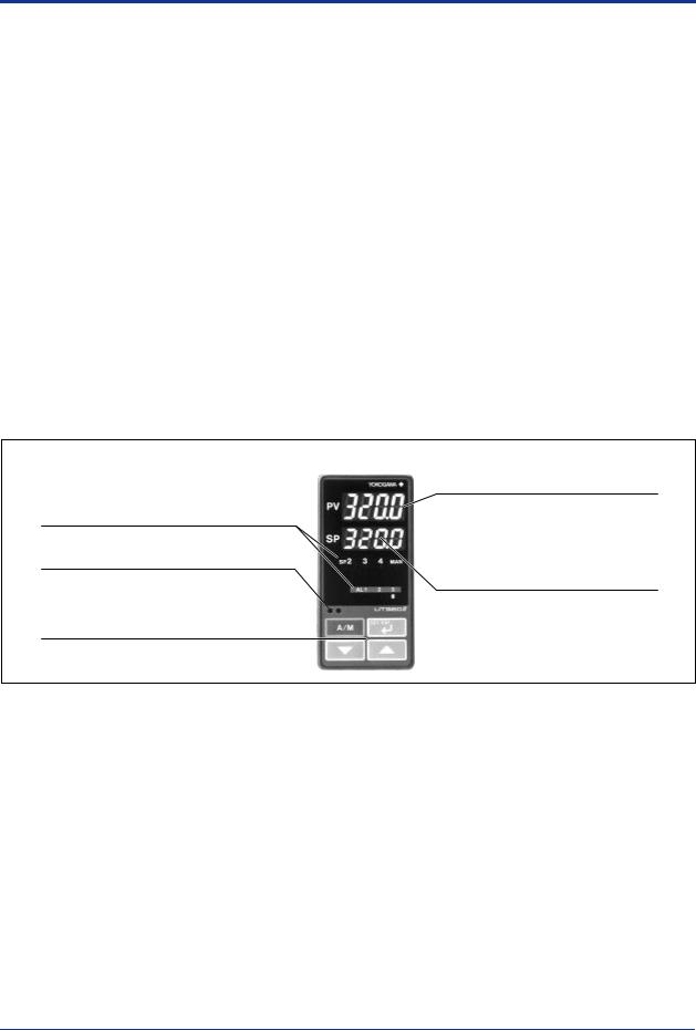
Status lamps
Alarm (AL1, 2, 3), Manual (MAN).
Setpoint No (SP2, 3, 4). in use.
Communication port for light loader
Parameters are set via communication from a personal computer.
Operational keys
Increase/Decrease the setting data ( , )
Select parameter/Enter the setting data (SET/ENT) A/M mode switching (A/M)
LED display unit (for PV)
Display PV, and error code when error is detected.
LED display unit (for SP)
Display setpoint (SP), output value, and setting item/value of parameters.
All Rights Reserved. Copyright © 2000, Yokogawa Electric Corporation |
GS 05D01D02-02E 3rd Edition Jul. 30, 2004-00 |
<<Contents>> <<Index>> |
4 |
● Communication Functions (optional)
This controller has a communication function and can be connected to a personal computer, programmable logic controller, or other /GREEN series controllers.
Communication protocol Computer link communication:
Communication protocol with a personal computer.
Ladder communication:
Communication protocol with programmable logic controller made.
MODBUS communication:
Communication protocol with a personal computer or PCL.
Coordinated operation:
Communication protocol to coordinate operation with two or more GREEN series controllers. The UT320 can be connected as a master station or a slave station.
Communication interface Communication protocol:
Computer link, ladder communication, MODBUS communication or coordinated operation
Standards: EIA RS485
Maximum number of connectable controllers: 31 GREEN series controllers
Maximum communication distance: 1,200 m Communication method:
Two-wire half duplex or four-wire half duplex, start-stop synchronization, nonprocedural
Communication rate:
600, 1200, 2400, 4800, 9600 bps
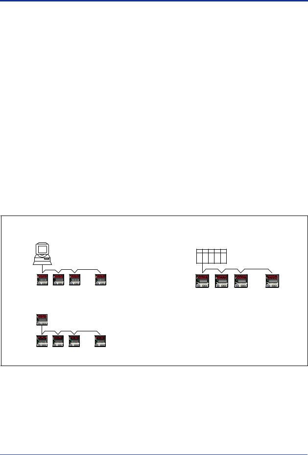
Examples of Communication System Configuration Diagram
(1) Computer link communication/MODBUS communication |
(2) Ladder communication |
MELSEC-A
Personal computer
PLC
PV PV PV PV
UT350/UT320 |
UT350/UT320 |
|
Digital indicating controller |
||
Digital indicating controller |
||
|
||
(3) Coordinated operation |
|
|
UP350 Program controller |
|
|
or UT350/UT320 Digital indicating controller |
|
|
UT350/UT320 |
|
|
Digital indicating controller |
|
All Rights Reserved. Copyright © 2000, Yokogawa Electric Corporation |
GS 05D01D02-02E 3rd Edition Jul. 30, 2004-00 |
 Loading...