


User’s
Manual
|
|
|
|
|
|
|
|
|
|
|
l |
|
|
|
|
|
|
|
|
|
|
|
|
a |
|
|
|
|
|
|
|
|
|
|
|
|
n |
|
|
|
|
|
|
|
|
|
|
tio |
|
|
|
|
|||
|
|
|
|
|
c |
|
|
|
|
|
|
|
|
|
|
|
n |
|
|
|
|
|
|
|
t |
||
|
|
u |
|
|
|
|
|
|
|
|
|
||
|
F |
|
|
|
|
|
|
|
|
|
n |
||
|
|
|
|
|
|
|
|
|
|
|
e |
|
|
UM33A |
|
|
|
|
|
|
|
|
m |
|
|
||
|
|
|
|
|
|
|
e |
|
|
|
|
||
|
|
|
|
|
|
|
c |
|
|
|
|
|
|
|
|
|
|
|
n |
|
|
|
|
|
|
||
|
|
|
|
a |
|
|
|
|
|
|
|
|
|
|
|
|
h |
|
|
|
|
|
|
|
|
|
|
|
n |
|
|
|
|
|
|
|
|
|
|
||
|
E |
|
|
|
|
|
|
|
|
|
|
|
|
Digital Indicator with Alarms User’s Manual
IM 05P03D21-01EN
IM 05P03D21-01EN
4th Edition
Product Registration
Thank you for purchasing YOKOGAWA products.
YOKOGAWA provides registered users with a variety of information and services. Please allow us to serve you best by completing the product registration form accessible from our homepage.
http://www.yokogawa.com/ns/reg/

Introduction
Thank you for purchasing the UM33A digital indicator with alarms (hereinafter referred to as UM33A).
This manual describes how to use UM33A functions other than UM33A’s communication function and ladder sequence function. Please read through this user’s manual carefully before using the product.
Note that the manuals for the UM33A comprise the following six documents:
● Printed manual
Manual Name |
Manual Number |
Description |
|
UM33A |
IM 05P03D21-11EN |
This manual describes the basic operation |
|
Operation Guide |
method. |
||
|
|||
Precautions on the Use of |
IM 05P01A01-11EN |
This manual is always delivered even if ‘without |
|
the UTAdvanced Series |
|
manuals’ was selected. |
● Electronic manuals
Manual Name |
Manual Number |
Description |
||
UM33A |
IM 05P03D21-11EN |
This is identical to the printed manual. |
||
Operation Guide |
||||
|
|
|
||
UM33A |
|
This manual. It describes the usage of all |
||
IM 05P03D21-01EN |
functions except the ladder sequence and |
|||
User’s Manual |
||||
|
communication functions. |
|
||
|
|
|
||
UTAdvanced Series |
|
This manual describes how to use UM33A |
||
Communication Interface |
IM 05P07A01-01EN |
in Ethernet and serial communications. For |
||
(RS-485, Ethernet) |
communication wiring, see the Operation Guide |
|||
|
||||
User’s Manual |
|
or User’s Manual. |
|
|
LL50A Parameter Setting |
|
This manual describes how to install and |
||
Software Installation |
IM 05P05A01-01EN |
|||
uninstall the LL50A. |
|
|||
Manual |
|
|
||
|
|
|
||
|
|
This manual describes how to use the LL50A, |
||
LL50A Parameter Setting |
IM 05P05A01-02EN |
ladder sequence function, peer-to-peer |
||
Software User’s Manual |
communication, and network profile creating |
|||
|
||||
|
|
function. |
|
|
Precautions on the Use of |
IM 05P01A01-11EN |
This manual is always delivered even if ‘without |
||
the UTAdvanced Series |
|
manuals’ was selected. |
|
|
* User’s Manual can be downloaded from a website. |
|
|||
http://www.yokogawa.com/ns/ut/im/ |
|
|||
● General Specifications |
|
|
||
General Specification Name |
GS Number |
|||
UM33A Digital Indicator with Alarms |
|
GS 05P03D21-01EN |
||
|
|
|
||
LL50A Parameter Setting Software |
|
GS 05P01A01-01EN |
||
|
|
|
|
|
*The last two characters of the manual number and general specification number indicate the language in which the manual is written.
●Authorised Representative in the EEA
Authorised Representative in the EEA
Yokogawa Europe BV. (Address: Euroweg 2 , 3825 HD Amersfoort, The Netherlands) is the Authorised Representative of Yokogawa Electric Corporation for this Product in the EEA.
Target Readers
This guide is intended for the following personnel;
●Engineers responsible for installation, wiring, and maintenance of the equipment.
●Personnel responsible for normal daily operation of the equipment.
4th Edition : Mar. 2016 (YK)
All Rights Reserved, Copyright © 2010 Yokogawa Electric Corporation
IM 05P03D21-01EN
i
Notice
●The contents of this manual are subject to change without notice as a result of continuing improvements to the instrument’s performance and functions.
●Every effort has been made to ensure accuracy in the preparation of this manual.
Should any errors or omissions come to your attention, however, please inform
Yokogawa Electric’s sales office or sales representative.
●Under no circumstances may the contents of this manual, in part or in whole, be transcribed or copied without our permission.
Trademarks
●Our product names or brand names mentioned in this manual are the trademarks or registered trademarks of Yokogawa Electric Corporation (hereinafter referred to as YOKOGAWA).
●Microsoft, MS-DOS, Windows, Windows XP, Windows Vista, and Windows 7 are either registered trademarks or trademarks of Microsoft Corporation in the United States and/or other countries.
●Adobe, Acrobat, and Postscript are either registered trademarks or trademarks of
Adobe Systems Incorporated.
●Ethernet is a registered trademark of XEROX Corporation in the United States.
●Modbus is a registered trademark of Schneider Electric.
●CC-Link is a registered trademark of CC-Link Partner Association (CLPA.)
●We do not use the TM or ® mark to indicate these trademarks or registered trademarks in this user’s manual.
●All other product names mentioned in this user’s manual are trademarks or registered trademarks of their respective companies.
Safety Precautions
This instrument is a product of Installation Category II of IEC/EN/CSA/UL61010-1, IEC/ EN61010-2-201, IEC/EN61010-2-030 Safety Standards and Class A of EN61326-1, EN55011 (EMC Standards).
CAUTION
This instrument is an EMC class A product. In a domestic environment, this product may cause radio interference in which case the user needs to take adequate measures.
The instrument is a product rated Measurement Category O (other). * Measurement Category O (other)
This category applies to electric equipment that measures a circuit connected to a low-voltage facility and receives power from stationary equipment such as electric switchboards.
To use the instrument properly and safely, observe the safety precautions described in this user’s manual when operating it. Use of the instrument in a manner not prescribed herein may compromise protection features inherent in the device. We assume no liability for or warranty on a fault caused by users’ failure to observe these instructions.
This instrument is designed to be used within the scope of Measurement Category O (other) and is dedicated for indoor use.
ii
IM 05P03D21-01EN

Notes on the User’s Manual
•This user’s manual should be readily accessible to the end users so it can be referred to easily. It should be kept in a safe place.
•Read the information contained in this manual thoroughly before operating the product.
•The purpose of this user’s manual is not to warrant that the product is well suited to any particular purpose, but rather to describe the functional details of the product.
Safety, Protection, and Modification of the Product
The following symbols are used in the product and user’s manuals to indicate safety precautions:
“Handle with Care” (This symbol is attached to the part(s) of the product to indicate that the user’s manual should be referred to in order to protect the operator and the instrument from harm.)
AC
AC/DC
The equipment wholly protected by double insulation or reinforced insulation.
Functional grounding terminal (Do not use this terminal as a protective grounding terminal.)
•In order to protect the system controlled by this product and the product itself, and to ensure safe operation, observe the safety precautions described in this user’s
manual. Use of the instrument in a manner not prescribed herein may compromise the product’s functions and the protection features inherent in the device. We assume no liability for safety, or responsibility for the product’s quality, performance or functionality should users fail to observe these instructions when operating the product.
•Installation of protection and/or safety circuits with respect to a lightning protector; protective equipment for the system controlled by the product and the product itself; foolproof or failsafe design of a process or line using the system controlled by the product or the product itself; and/or the design and installation of other protective and safety circuits are to be appropriately implemented as the customer deems necessary.
•Be sure to use the spare parts approved by YOKOGAWA when replacing parts or consumables.
•This product is not designed or manufactured to be used in critical applications that directly affect or threaten human lives. Such applications include nuclear power equipment, devices using radioactivity, railway facilities, aviation equipment, air navigation facilities, aviation facilities, and medical equipment. If so used, it is the user’s responsibility to include in the system additional equipment and devices that ensure personnel safety.
•Modification of the product is strictly prohibited.
•This product is intended to be handled by skilled/trained personnel for electric devices.
•This product is UL Recognized Component. In order to comply with UL standards, end-products are necessary to be designed by those who have knowledge of the requirements.
IM 05P03D21-01EN |
iii |

WARNING
●Power Supply
Ensure that the instrument’s supply voltage matches the voltage of the power supply before turning ON the power.
●Do Not Use in an Explosive Atmosphere
Do not operate the instrument in locations with combustible or explosive gases or steam. Operation in such environments constitutes an extreme safety hazard. Use of the instrument in environments with high concentrations of corrosive gas (H2S, SOX, etc.) for extended periods of time may cause a failure.
●Do Not Remove Internal Unit
The internal unit should not be removed by anyone other than YOKOGAWA’s service personnel. There are dangerous high voltage parts inside. Additionally, do not replace the fuse by yourself.
●Damage to the Protective Construction
Operation of the instrument in a manner not specified in this user’s manual may damage its protective construction.
Warning and Disclaimer
•YOKOGAWA makes no warranties regarding the product except those stated in the WARRANTY that is provided separately.
•The product is provided on an “as is” basis. YOKOGAWA assumes no liability to any person or entity for any loss or damage, direct or indirect, arising from the use of the product or from any unpredictable defect of the product.
Notes on Software
•YOKOGAWA makes no warranties, either expressed or implied, with respect to the software’s merchantability or suitability for any particular purpose, except as specified in the terms of the separately provided warranty.
•This software may be used on one specific machine only.
•To use the software on another machine, the software must be purchased again separately.
•It is strictly prohibited to reproduce the product except for backup purposes.
•Store the software CD-ROM (the original medium) in a safe place.
•All reverse-engineering operations, such as reverse compilation or the reverse assembly of the product are strictly prohibited.
•No part of the product’s software may be transferred, converted, or sublet for use by any third party, without prior written consent from YOKOGAWA.
Handling Precautions for the Main Unit
•The instrument comprises many plastic components. To clean it, wipe it with a soft, dry cloth. Do not use organic solvents such as benzene or thinner for cleaning, as discoloration or deformation may result.
•Keep electrically charged objects away from the signal terminals. Not doing so may cause the instrument to fail.
•Do not apply volatile chemicals to the display area, operation keys, etc. Do not leave the instrument in contact with rubber or PVC products for extended periods. Doing so may result in failure.
•If the equipment emits smoke or abnormal smells or makes unusual noises, turn OFF the instrument’s power immediately and unplug the device. In such an event, contact your sales representative.
iv
IM 05P03D21-01EN

Checking the Contents of the Package
Unpack the box and check the contents before using the product. If the product is different from that which you have ordered, if any parts or accessories are missing, or if the product appears to be damaged, contact your sales representative.
UM33A Main Unit
The UM33A main units have nameplates affixed to the side of the case.
Check the model and suffix codes inscribed on the nameplate to confirm that the product received is that which was ordered.
No. (Instrument number)
When contacting your sales representative, inform them of this number, too.
Note
The last digit of the display code (-x0) has been changed into the case color code.
Model and Suffix Codes of UM33A
|
|
|
|
|
|
Optional |
|
Model |
Suffix code |
|
suffix |
Description |
|||
|
|
|
|
|
|
code |
|
UM33A |
|
|
|
|
|
|
Digital Indicator with Alarms (Power supply: 100-240 V AC) (provided with |
|
|
|
|
|
|
retransmission output or 15 V DC loop power supply, 2 DIs, and 3 DOs) |
|
|
|
|
|
|
|
|
|
Type 1: |
-0 |
|
|
|
|
|
Standard type |
Basic |
|
|
|
|
|
||
|
|
|
|
|
|
|
|
|
|
0 |
|
|
|
|
None |
Type 2: |
|
1 |
|
|
|
|
1 additional DO (c-contact relay), RS-485 communication (Max.38.4 kbps, |
|
|
|
|
|
2-wire/4-wire) (*1) |
||
Functions |
|
|
|
|
|
|
|
|
2 |
|
|
|
|
1 additional DO (c-contact relay) |
|
|
|
|
|
|
|
||
|
|
3 |
|
|
|
|
6 additional DOs (c-contact relay; 1 point and open collector; 5 points) |
Type 3: |
|
|
0 |
|
|
|
None |
Open networks |
|
|
|
|
CC-Link communication (with Modbus master function) (*2) |
||
|
|
|
|
-1 |
|
|
English (Default. Can be switched to other language by the setting.) |
Display language (*3) |
-2 |
|
|
German (Default. Can be switched to other language by the setting.) |
|||
-3 |
|
|
French (Default. Can be switched to other language by the setting.) |
||||
|
|
|
|
|
|
||
|
|
|
|
-4 |
|
|
Spanish (Default. Can be switched to other language by the setting.) |
Case color |
|
|
|
|
0 |
|
White (Light gray) |
|
|
|
|
1 |
|
Black (Light charcoal gray) |
|
|
|
|
|
|
|
||
|
|
|
|
|
|
/LP |
24 V DC loop power supply (*4) |
Optional suffix codes |
|
|
/DC |
Power supply 24 V AC/DC |
|||
|
|
/CT |
Coating (*5) |
||||
|
|
|
|
|
|
||
|
|
|
|
|
|
/CV |
Terminal cover |
|
*1: |
|
When /LP option is specified, the RS-485 communication of the Type 2 code “1” is 2-wire |
||||
|
|
|
|
|
system. |
|
|
|
*2: |
|
Type 3 code “3” can be specified only when the Type 2 code is “0” or “2”. |
||||
|
*3: |
|
English, German, French, and Spanish are available for the guide display. |
||||
|
*4: |
|
The /LP option can be specified only when the code for Type 2 code is any of “0”, “1” or “2”, |
||||
|
|
|
|
|
and the Type 3 code is “0”. |
||
|
*5: |
|
When the /CT option is specified, the UM33A does not conform to the safety standards (UL |
||||
|
|
|
|
|
and CSA) and CE marking (Products with /CT option are not intended for EEA-market). |
||
IM 05P03D21-01EN |
v |

Coating Treatment
(1)HumiSeal coating treatment
Apply HumiSeal coating to the printed circuit board assembly.
Do not apply HumiSeal coating to the following parts: connector, gold-plated contact area, relay part, RJC device, and in the vicinity of the push switch/LED lamp.
(2)Apply terminal coating to the gold-plated contact area on the printed circuit board.
Notes
▪There are two treatments as described above, but we do not guarantee their effectiveness.
We do not supply any test data on these treatments.
▪Do not apply any treatment to the screw terminal area on the back side of the instrument.
Accessories
The product is provided with the following accessories according to the model and suffix codes. Check that none of them are missing or damaged.
1 |
2 |
3 |
|
4 |
|
No. |
Product Name |
Quantity |
Remark |
|
|
|
|
|
|
1 |
Brackets |
2 |
Part number: L4502TP (For fixing the right and |
|
left parts) |
||||
|
|
|
||
2 |
Unit label |
1 |
Part number: L4502VZ |
|
|
|
|
|
|
3 |
Tag label |
1 |
Part number: L4502VE (Only when ordered.) |
|
|
|
|
|
|
4 |
Operation Guide |
1 |
A3 size, x 4 |
|
|
|
|
|
How to use the unit label
•Affixing the unit label
Affix the unit label to the front panel. If necessary, combine with unit prefixes. Affix it so that the LCD area is not blocked.
•Maintenance port seals
Maintenance port seals (two spares) are available. Use them if the seal affixed to the UTAdvanced controller loses its adhesiveness.
•TAG No. labels
TAG No. labels (two pieces) are available. Use them if necessary.
vi
IM 05P03D21-01EN

Accessory (sold separately)
The following lists an accessory sold separately.
• LL50A Parameter Setting Software
Model |
Suffix code |
|
Description |
LL50A |
-00 |
Parameter Setting Software |
|
|
|
|
|
• External Precision Resistor |
|
|
|
|
|
|
|
Model |
Suffix code |
Description |
|
|
|
|
|
X010 |
See the General Specifications (*) |
Resistance Module |
|
|
|
|
|
*: Necessary to input the current signal to the voltage input terminal.
• Terminal cover
For UM33A, Model: UTAP002
• Brackets
Part number L4502TP (2 pieces for fixing the right and left parts)
•User’s Manual (A4 size)
*User’s Manual can be downloaded from a website.
IM 05P03D21-01EN |
vii |
Symbols Used in This Manual
This symbol is used on the instrument. It indicates the possibility of injury to the user or damage to the instrument, and signifies that the user must refer to the user’s manual for special instructions. The same symbol is used in the user’s manual on pages that the user needs to refer to, together with the term “WARNING” or “CAUTION.”
WARNING
Calls attention to actions or conditions that could cause serious or fatal injury to the user, and indicates precautions that should be taken to prevent such occurrences.
CAUTION
Calls attention to actions or conditions that could cause injury to the user or damage to the instrument or property and indicates precautions that should be taken to prevent such occurrences.
Note
Identifies important information required to operate the instrument.
Indicates related operations or explanations for the user’s reference.
[ ] Indicates a character string displayed on the display.
Setting Display
Indicates a setting display and describes the keystrokes required to display the relevant setting display.
Setting Details
Provides the descriptions of settings.
Description
Describes restrictions etc. regarding a relevant operation.
viii
IM 05P03D21-01EN

How to Use This Manual
For the communication functions, see the Communication Interface manual. This user’s manual is organized into Chapters 1 to 17 as shown below.
Chapter |
Title and Description |
1Introduction to Functions
Describes the main functions of the UM33A.
2UM33A Operating Procedures
Describes the flow from unpacking to regular operations.
3Part Names
Describes part names and functions on the front panel.
4Basic Operation
Describes basic operation of the UM33A.
5Quick Setting Function
Describes the minimum necessary settings for operation.
6Monitoring of Regular Operations
Describes monitoring displays of regular operations and operation.
7Input (PV) Functions
Describes PV input.
8Functions
Provides function block diagrams.
9Alarm Functions
Describes alarm output and status output.
10Output (Retransmission) Functions
Describes output functions.
11Contact Input/Output Functions
Describes contact input/output functions.
12Display, Key, and Security Functions
Describes display, user function key and security functions.
13Parameter Initialization
Describes the initialization to factory default values and to user default values.
Power Failure Recovery Processing/Power Frequency Setting/Other Settings
14Describes operations performed after momentary power interruption and power failures.
15Troubleshooting, Maintenance, and Inspections
Describes troubleshooting, maintenance, periodic inspections, and disposal.
16Installation and Wiring
Describes installation and wiring.
17Parameters
Provides parameter maps.
GS |
Specifications |
|
Provides the UM33A specifications. |
||
|
IM 05P03D21-01EN |
ix |

Blank Page

Contents
|
Introduction............................................................................................................................ |
i |
|
|
Target Readers...................................................................................................................... |
i |
|
|
Notice |
................................................................................................................................ |
ii |
|
Trademarks........................................................................................................................... |
ii |
|
|
Safety Precautions................................................................................................................ |
ii |
|
|
Handling Precautions for the Main Unit............................................................................... |
iv |
|
|
Checking the Contents of the Package................................................................................. |
v |
|
|
Model and Suffix Codes of UM33A....................................................................................... |
v |
|
|
Symbols Used in This Manual............................................................................................ |
viii |
|
|
How to Use This Manual...................................................................................................... |
ix |
|
Chapter 1 Introduction to Functions |
|
||
1.1 |
Quick Setting Function...................................................................................................... |
1-1 |
|
1.2 |
Input/Output Function....................................................................................................... |
1-2 |
|
1.3 |
Display and Key Functions............................................................................................... |
1-4 |
|
1.4 |
Communication Functions................................................................................................ |
1-5 |
|
1.5 |
Definition of Main Symbols and Terms.............................................................................. |
1-7 |
|
Chapter 2 UM33A Operating Procedures |
|
||
2.1 |
UM33A Operating Procedures.......................................................................................... |
2-1 |
|
Chapter 3 Part Names |
|
|
|
3.1 |
Names and Functions of Display Parts............................................................................. |
3-1 |
|
3.2 |
Names and Functions of Keys.......................................................................................... |
3-2 |
|
3.3 |
List of Display Symbols..................................................................................................... |
3-4 |
|
3.4 |
Brief Description of Setting Details (Parameters)............................................................... |
3-6 |
|
Chapter 4 Basic Operation |
|
||
4.1 |
Overview of Display Switch and Operation Keys.................................................................... |
4-1 |
|
4.2 |
How to Set Parameters..................................................................................................... |
4-4 |
|
Chapter 5 Quick Setting Function |
|
||
5.1 |
Setting Using Quick Setting Function............................................................................... |
5-1 |
|
5.2 |
Restarting Quick Setting Function.................................................................................... |
5-6 |
|
Chapter 6 Monitoring of Regular Operations |
|
||
6.1 |
Monitoring of Operation Displays...................................................................................... |
6-1 |
|
|
6.1.1 |
Operation Display Transitions............................................................................. |
6-1 |
6.2 |
Setting Alarm Setpoint...................................................................................................... |
6-3 |
|
6.3 |
Releasing On-State (Latch) of Alarm Output.................................................................... |
6-4 |
|
6.4 |
Confirmation of PV peak and bottom value...................................................................... |
6-5 |
|
Chapter 7 Input (PV) Functions |
|
||
7.1 |
Setting Functions of PV Input........................................................................................... |
7-1 |
|
|
7.1.1 Setting Input Type, Unit, Range, Scale, and Decimal Point Position.................. |
7-1 |
|
|
7.1.2 Setting Burnout Detection for Input..................................................................... |
7-4 |
|
|
7.1.3 Setting Reference Junction Compensation (RJC) or External Reference |
|
|
|
|
Junction Compensation (ERJC).......................................................................... |
7-5 |
|
7.1.4 |
Correcting Input Value......................................................................................... |
7-6 |
|
|
(1) Setting Bias and Filter..................................................................................................... |
7-6 |
|
|
(2) Setting Square Root Extraction and Low Signal Cutoff Point.......................................... |
7-7 |
1
2
3
4
5
6
7
8
9
10
11
12
13
14
15
16
17
App
Index
IM 05P03D21-01EN |
xi |

Contents
|
(3) Setting 10-segment Linearizer |
........................................................................................7-8 |
7.2 |
Setting Input Sampling Period........................................................................................ |
7-10 |
Chapter 8 Functions
8.1 Function Block Diagrams.................................................................................................. 8-1
Chapter 9 Alarm Functions
9.1 |
Setting Alarm Type............................................................................................................ |
9-1 |
9.2 |
Setting Number of Alarm Groups to Use........................................................................... |
9-7 |
9.3 |
Setting Hysteresis to Alarm Operation.............................................................................. |
9-8 |
9.4 |
Delaying Alarm Output (Alarm Delay Timer)..................................................................... |
9-9 |
Chapter 10 Retransmission Output Functions
10.1 |
Setting Retransmission Output Terminal, Type, and Scales........................................... |
10-1 |
10.2 |
Setting 10-segment Linearizer for Output....................................................................... |
10-2 |
10.3 |
Changing Current Output Range.................................................................................... |
10-4 |
10.4 |
Setting Split Computation Output Function..................................................................... |
10-5 |
10.5 |
Using 15 V DC Loop Power Supply................................................................................ |
10-6 |
Chapter 11 Contact Input/Output Functions
11.1 |
Setting Contact Input Function......................................................................................... |
11-1 |
|
11.1.1 Setting Contact Input Function........................................................................... |
11-1 |
|
11.1.2 Changing Contact Type of Contact Input............................................................ |
11-3 |
11.2 |
Setting Contact Output Function...................................................................................... |
11-4 |
|
11.2.1 Setting Function of Contact Output.................................................................... |
11-4 |
|
11.2.2 Changing Contact Type of Contact Output......................................................... |
11-7 |
Chapter 12 Display, Key, and Security Functions
12.1 |
Setting Display Functions............................................................................................... |
12-1 |
|
|
12.1.1 |
Setting Active Color PV Display Function.......................................................... |
12-1 |
|
12.1.2 |
Masking Arbitrary Display Value in Operation Display....................................... |
12-3 |
|
12.1.3 |
Registering SELECT Display (Up to 5 Displays)............................................... |
12-4 |
|
12.1.4 |
Changing Event Display.................................................................................... |
12-5 |
|
12.1.5 |
Masking Least Significant Digit of PV Display................................................... |
12-6 |
|
12.1.6 |
Setting Economy Mode..................................................................................... |
12-7 |
|
12.1.7 |
Selecting the Initial Operation Display that Appears at Power ON.................... |
12-7 |
|
12.1.8 |
Setting Message Function................................................................................. |
12-8 |
|
12.1.9 |
Switching Guide Display Language................................................................... |
12-8 |
|
12.1.10 |
Changing Guide Scroll Speed........................................................................... |
12-9 |
|
12.1.11 |
Turning Guide Display ON/OFF........................................................................ |
12-9 |
|
12.1.12 |
Setting Automatic Return to Operation Display................................................. |
12-9 |
|
12.1.13 Setting Brightness Adjustment of LCD and Display Update Cycle.................. |
12-10 |
|
12.2 Assigning Function to User Function Key...................................................................... |
12-11 |
||
12.3 |
Setting Security Functions............................................................................................ |
12-13 |
|
|
12.3.1 |
Setting or Clearing the Password.................................................................... |
12-13 |
|
12.3.2 |
Setting Parameter Display Level..................................................................... |
12-13 |
|
12.3.3 |
Locking (Hiding) Parameter Menu Display...................................................... |
12-14 |
|
12.3.4 |
Key Lock.......................................................................................................... |
12-15 |
|
12.3.5 |
Setting Display/Non-display of Operation Display........................................... |
12-15 |
|
12.3.6 |
Prohibiting Writing via Communication............................................................ |
12-15 |
12.4 Confirmation of Key and I/O Condition and Version..................................................... |
12-16 |
||
|
12.4.1 Confirmation of Key and I/O Condition............................................................ |
12-16 |
|
|
12.4.2 |
Confirmation of Version................................................................................... |
12-18 |
xii
IM 05P03D21-01EN

|
|
|
Contents |
Chapter 13 |
Parameter Initialization |
|
|
|
13.1 |
Initializing Parameter Settings to Factory Default Values............................................... |
13-1 |
|
13.2 |
Registering and Initializing User Default Values............................................................. |
13-2 |
|
|
13.2.1 |
13-2 |
|
|
13.2.2 |
13-2 |
Chapter 14 Power Failure Recovery Processing / Power Frequency Setting / |
|
||
|
Other Settings |
|
|
|
14.1 |
Remedies if Power Failure Occurs during Operations.................................................... |
14-1 |
|
14.2 |
Power Frequency Setting................................................................................................ |
14-2 |
|
14.3 |
Setting Time between Powering on Indicator and Starting Monitor (Restart Timer)....... |
14-3 |
Chapter 15 Troubleshooting, Maintenance, and Inspections |
|
||
|
15.1 |
Troubleshooting.............................................................................................................. |
15-1 |
|
|
15.1.1 |
15-1 |
|
|
15.1.2 |
15-2 |
|
|
15.1.3 |
15-4 |
|
15.2 |
Maintenance................................................................................................................... |
15-9 |
|
|
15.2.1 |
15-9 |
|
|
15.2.2 |
15-9 |
|
|
15.2.3 |
15-9 |
|
15.3 |
Periodic Maintenance .................................................................................................. |
15-10 |
|
15.4 |
Disposal......................................................................................................................... |
15-11 |
Chapter 16 |
Installation and Wiring |
|
|
|
16.1 |
Installation Location........................................................................................................ |
16-1 |
|
16.2 |
Mounting Method............................................................................................................ |
16-3 |
|
16.3 |
External Dimensions and Panel Cutout Dimensions.................................................................... |
16-4 |
|
16.4 |
Wiring |
16-5 |
|
|
16.4.1 |
16-5 |
|
|
16.4.2 |
16-7 |
|
|
16.4.3 .......................................................................................... |
16-8 |
|
|
16.4.4 ....................................................................................... |
16-9 |
|
|
16.4.5 ......................................................................... |
16-11 |
|
|
16.4.6 ................................................................ |
16-11 |
|
|
16.4.7 ................................................................ |
16-11 |
|
|
16.4.8 ........................................................ |
16-12 |
|
|
16.4.9 ....................................................... |
16-14 |
|
|
16.4.10 .......................................................................................Power Supply Wiring |
16-16 |
|
16.5 |
Attaching ......................................................................and Detaching Terminal Cover |
16-17 |
Chapter 17 Parameters |
|
||
|
17.1 |
Parameter ...............................................................................................................Map |
17-1 |
|
17.2 |
List of Parameters........................................................................................................... |
17-6 |
|
|
17.2.1 ....................................................................................... |
17-6 |
|
|
17.2.2 ............................................................................................. |
17-8 |
Appendix Input and Output ................................................................................Table |
|
||
|
Appendix 1 Input ..........................................................................................and Output Table |
App-1 |
|
Revision Information
1
2
3
4
5
6
7
8
9
10
11
12
13
14
15
16
17
App
Index
IM 05P03D21-01EN |
xiii |

Blank Page
Chapter 1 Introduction to Functions
1.1Quick Setting Function
The Quick setting function is a function to easily set the basic function of the indicator.
Buy and
Unpacking
Installation
and Wiring
Setup


 8
8 
Check the contents.
Installation and Wiring: Chapter 16
Install and wire a indicator, and then turn on the power.
Q:What should I do to perform operate immediately?
First, I want to set the input and output.
A:Use the Quick setting function to perform the setup easily.
Quick setting function: Chapter 5
Operation
1
Functions to Introduction
IM 05P03D21-01EN |
1-1 |
1.2Input/Output Function
PV Input (equipped as standard)
PV input is a universal input to arbitrarily set the type and range for the thermocouple (TC), resistance-temperature detector (RTD), and DC voltage/current.
► Chapter 7 Input (PV) Functions
TC mV
V
mA
Current
RTD
8 |
Relay contact |
2-wire transmitter
Retransmission Output (equipped as standard)
Retransmission output outputs a PV input value (PV), alarm output value (ALM) and the like as an analog signal to, for example, the recorder.
► Chapter 11 Contact Input/Output Functions
External device such as recorder etc.
UM33A
Current
8 
Contact Input
Two contact inputs are incorporated in UM33A. The PV peak value and PV bottom value can be reset, and the alarm latch can be released.
► Chapter 11 Contact Input/Output Functions
Contact Output
Up to 9 contact outputs can be incorporated. Contact output can output events such as alarms.
For details, see the table of Model and Suffix Codes.
► Chapter 9 Alarm Functions
1-2 |
IM 05P03D21-01EN |

1.2 Input/Output Function
24 V DC Loop Power Supply (optional suffix code: /LP)
24 V DC loop power supply can be supplied to 2-wire transmitter.
► 16.4.7 24 V DC Loop Power Supply Wiring
UM33A
2-wire transmitter
8 
1
Functions to Introduction
IM 05P03D21-01EN |
1-3 |
1.3Display and Key Functions
Employing a 14-segment, active color LCD greatly increases the monitoring and operating capabilities.
Active Color PV Display (display color change)
The active color PV display function changes the PV display color (red or white) when abnormality occurs in PV etc.
► 12.1.1 Setting Active Color PV Display Function |
|
Normal |
Abnormal |
8 |
8 |
Guide Display
The guide is displayed on PV display when setting parameters. This guide can be turned on/off with the Fn key.
|
The scrolling guide is displayed |
8 |
when setting parameters. |
Multilingual Guide Display
English, German, French, or Spanish can be displayed in Guide display.
► 12.1.9 Switching Guide Display Language
Parameter Display Level
To intended use of the operator, the display level of the parameter can be set.
► Chapter 17 Parameters
User Function Keys
The UM33A has a user function key (Fn).
Assign a function to a user function key to use it as an exclusive key.
► 12.2 Assigning Function to User Function Key
1-4 |
IM 05P03D21-01EN |
1.4Communication Functions
The UM33A can use RS-485 communication by specifying the suffix code.
► UTAdvanced Series Communication Interface (RS-485, Ethernet) User’s Manual
RS-485 Communication (Modbus communication, PC link communication, and
Ladder communication)
The UM33A can communicate with PCs, PLCs, touch panels, and other devices.
PC
RS-485/ |
Model: ML2 of YOKOGAWA is recommended. |
RS-232C |
|
converter |
|
|
Up to 31 connected slaves with a maximum length of 1200m |
8 |
8 |
8 |
8 |
CC-Link Communication
The UM33A can be used as the slave devices for CC-Link communication. Read-out of PV, operation or alarm status, and SP setting can be done by accessing the remote I/O on the master unit of CC-Link.
PLC
CC-Link Master
CC-Link communication
CC-Link Slave / Modbus Master


 8
8
Modbus/RTU communication
Max. 1200 m, number of connected slaves: 31


 8
8


 8
8


 8
8


 8
8
Modbus Slave Modbus Slave Modbus Slave Modbus Slave
1
Functions to Introduction
IM 05P03D21-01EN |
1-5 |
1.4 Communication Functions
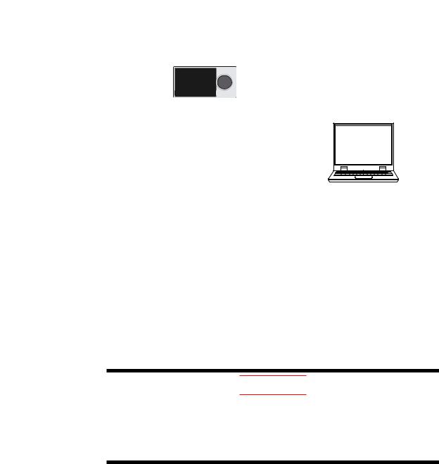
Light-loader Communication
Use the LL50A to set parameters. Attach the adapter to the front of the indicator to communicate.
► Light-loader function: LL50A Parameter Setting Software User’s Manual
Light-loader 


 8
8 


adapter
LL50A Parameter Setting Software
To USB terminal |
Dedicated cable
Maintenance Port Communication (Power supply is not required for the
UM33A)
Maintenance port is used to connect with the dedicated cable when using LL50A Parameter Setting Software (sold separately). The parameters can be set without supplying power to the UM33A.
LL50A Parameter Setting Software
To USB terminal 
Dedicated cable
CAUTION
When using the maintenance port, do not supply power to the indicator. Otherwise, the indicator does not work normally.
If power is supplied to the indicator while the cable is connected, or the cable is connected to the indicator already turned on, unplug the cable and turn on the indicator again. The indicator returns to the normal condition.
1-6 |
IM 05P03D21-01EN |
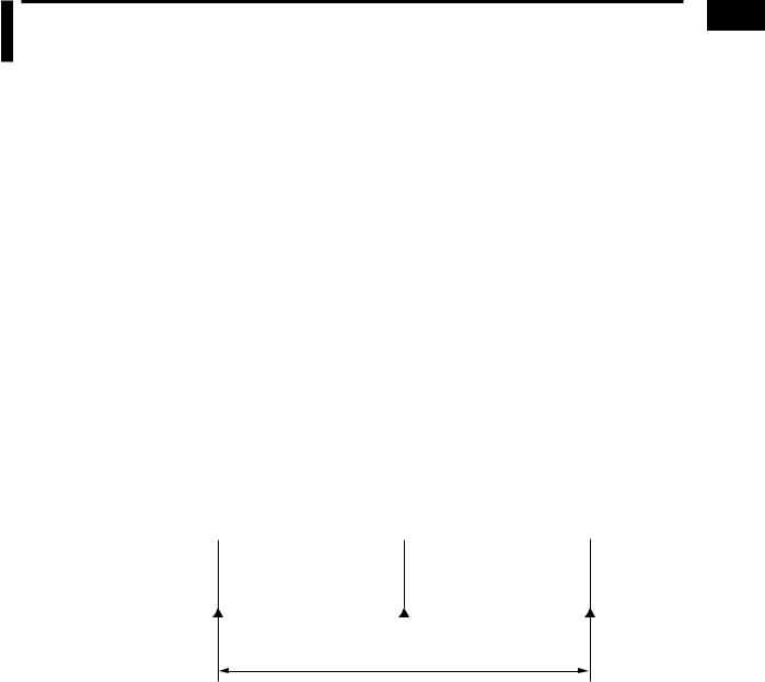
1.5Definition of Main Symbols and Terms
Main Symbol
PV: Measured input value
A1 to A8: Alarm setpoint
PEAK: PV peak value BOTM: PV bottom values
► 16.4 Wiring
Engineering Units
Input range (scale): the PV range low limit is set to 0%, and the high limit is set to 100% for conversion.
Input range (scale) span: the PV range span is set to 100% for conversion.
In this manual, the parameter setting range is described as the “input range” and “input range span.” This means that engineering units are required to be set. Set a temperature for temperature input.
The following describes a conversion example.
When the PV input range is 100 to 600°C, 0% of the PV range is equivalent to 100°C, 50% of the PV range is equivalent to 350°C, and 100% of the PV range is equivalent to 600°C.
100% of the PV range span is equivalent to 500°C. 20% of the PV range span is equivalent to 100°C.
Minimum value of PV input range |
|
Maximum value of PV input range |
||
100°C |
350°C |
600°C |
||
|
|
|
|
|
1
Functions to Introduction
0% of |
PV input |
range |
50% of PV input range |
100% of |
PV input |
range |
100% of PV input range span = 500°C
The above applies to the scale for voltage and current input.
IM 05P03D21-01EN |
1-7 |

Blank Page
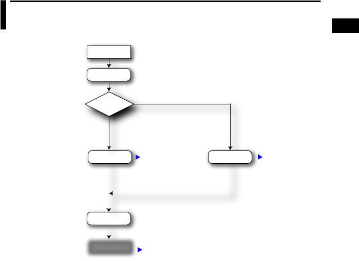
Chapter 2 UM33A Operating Procedures
2.1UM33A Operating Procedures
Installation
and Wiring
Power ON
Use Quick setting function?
YES
Install and wire a indicator.  Installation and Wiring: Chapter 16
NO
Intput setup |
Quick setting function: |
Intput |
setup |
Section 7.1 |
||
|
|
|
Chapter 5 |
|
|
|
|
|
|
|
|
|
|
|
|
|
|
|
|
|
Other setup |
Set the other parameters as necessary. |
||
|
|
Monitoring of regular operations |
|
|
|
||
|
|
||
Operation |
|||
Regular operations: Chapter 6 |
|||
|
|
||
2
Procedures Operating UM33A
IM 05P03D21-01EN |
2-1 |

Blank Page

Chapter 3 Part Names
3.1Names and Functions of Display Parts
UM33A
(1) PV display
(3) Symbol display
(2)Group display 


(6)Key navigation indicator
(7)Parameter display level indicator
(4) Data display
8 
(5) Event indicator
(8) Security indicator
(2) + (3) + (4) : Setpoint display
No. in figure |
Name |
Description |
|
|
|
|
|
|
|
Displays PV. |
|
|
PV display |
Displays an error code if an error occurs. |
|
(1) |
Displays the scrolling guide in the Menu Display and |
||
(white or red) |
|||
|
Parameter Setting Display when the guide display ON/ |
||
|
|
||
|
|
OFF is set to ON. |
|
(2) |
Group display |
Displays a group number. |
|
(green) |
|||
|
|
||
(3) |
Symbol display |
Displays a parameter symbol. |
|
(orange) |
|||
|
|
(4)Data display (orange) Displays a parameter setpoint and menu symbol.
|
Event indicator |
Lit when the alarms 1 to 8 occur. |
|
|
|
|
(5) |
Event displays other than alarms can be set by the |
|||||
(orange) |
||||||
|
parameter. |
|
|
|
||
|
|
|
|
|
||
|
Key navigation |
Lit or blinks when the Up/Down or Left/Right arrow key |
||||
(6) |
indicator |
|||||
operation is possible. |
|
|
|
|||
|
(green) |
|
|
|
||
|
|
|
|
|
||
|
|
Displays the setting conditions of the parameter display |
||||
|
Parameter display |
level function. |
|
|
|
|
|
|
|
|
|
||
|
Parameter display level |
EASY |
PRO |
|
||
(7) |
level indicator |
|
||||
Easy setting mode |
Lit |
Unlit |
|
|||
|
(green) |
|
||||
|
Standard setting mode |
Unlit |
Unlit |
|
||
|
|
|
||||
|
|
Professional setting mode |
Unlit |
Lit |
|
|
|
|
|
|
|
|
|
(8) |
Security indicator (red) |
Lit if a password is set. The setup parameter settings are |
||||
locked. |
|
|
|
|||
3
Names Part
IM 05P03D21-01EN |
3-1 |

3.2Names and Functions of Keys
UM33A
|
|
|
|
|
|
|
|
(1) DISP key |
|
|
|
|
|
|
|
|
|
||
|
|
|
|
|
|
|
|
(2) PARA key |
|
|
|
|
|
|
|
|
|
||
|
|
|
|
|
|
|
|
||
|
|
|
|
|
|
|
|
||
|
|
|
|
|
|
|
|
(3) SET/ENTER key |
|
|
|
|
|
|
|
|
|
||
|
|
|
|
|
|
|
|
||
|
|
|
|
|
|
|
|
Up/Down/Left/Right arrow keys |
|
|
8 |
|
|
|
|
|
|
(6) User function keys |
|
|
|
|
|
|
|
|
|||
|
|
|
|
|
|
|
|
||
|
|
|
|
|
|
|
|
(4) Light-loader interface |
|
|
|
|
|
|
|
|
|
||
|
|
|
|
|
|
|
|
|
|
No. in figure |
Name |
|
|
|
|
|
|
Description |
|
|
|
Used to switch the Operation Displays. |
|||||||
|
DISP key |
Press the key in the Operation Display to switch the |
|||||||
(1) |
provided Select Displays. |
||||||||
|
|
Press the key in the Menu Display or Parameter Setting |
|||||||
|
|
Display to return to the Operation Display. |
|||||||
|
|
Hold down the key for 3 seconds to move to the Operation |
|||||||
|
|
Parameter Setting Display. |
|||||||
|
|
Hold down the key and the Left arrow key simultaneously |
|||||||
(2) |
PARA key |
for 3 seconds to move to the Setup Parameter Setting |
|||||||
Display. |
|||||||||
|
|
||||||||
|
|
Press the key in the Parameter Setting Display to return |
|||||||
|
|
to the Menu Display. Press the key once to cancel the |
|||||||
|
|
parameter setting (setpoint is blinking). |
|||||||
|
|
SET/ENTER key |
|||||||
|
|
Press the key in the Menu Display to move to the |
|||||||
|
|
Parameter Setting Display of the Menu. Press the key in |
|||||||
|
|
the Parameter Setting Display to transfer to the parameter |
|||||||
|
|
setting mode (setpoint is blinking), and the parameter can |
|||||||
|
|
be changed. Press the key during parameter setting mode |
|||||||
|
|
to register the setpoint. |
|||||||
|
SET/ENTER key |
Up/Down/Left/Right arrow keys |
|||||||
(3)Up/Down/ Left/Right Press the Left/Right arrow keys in the Menu Display to
arrow keys |
switch the Displays. |
|
Press the Up/Down arrow keys in the Parameter |
|
Setting Display to switch the Displays. |
|
Press the Up/Down arrow keys during parameter setting |
|
mode (setpoint is blinking) to change a setpoint. |
|
Press the Left/Right arrow keys during parameter setting |
|
mode (setpoint is blinking) to move between digits |
|
according to the parameter. |
|
It is the communication interface to the adapter cable |
(4)Light-loader interface when setting and storing parameters via PC. The LL50A
Parameter Setting Software (sold separately) is required.
The UM33A has Fn key.
(5)User function keys The user can assign a function to the key. The function is
set by the parameter.
3-2 |
IM 05P03D21-01EN |
3.2 Names and Functions of Keys
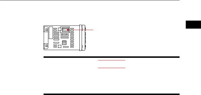
Maintenance Port (Power supply is not required for the UM33A).
The maintenance port is used to connect with the dedicated cable when using LL50A Parameter Setting Software (sold separately). The parameters can be set without
supplying power to the UM33A.
3
Maintenance port
Names Part
CAUTION
When using the maintenance port, do not supply power to the indicator. Otherwise, the indicator does not work normally.
If power is supplied to the indicator while the cable is connected, or the cable is connected to the indicator already turned on, unplug the cable and turn on the indicator again. The indicator returns to the normal condition.
IM 05P03D21-01EN |
3-3 |
 Loading...