


User’s
Manual
Model GX10/GX20/GP10/GP20
Paperless Recorder
User’s Manual
IM 04L51B01-01EN
8th Edition

Introduction
Thank you for purchasing the SMARTDAC+ Series GX10/GX20/GP10/GP20 (hereafter referred to as the GX or GP).
This manual explains how to use the GX/GP. Although the display of GX20 is used in this manual, GX10/GP10/GP20 can be operated similarly.
In this manual, the GX20/GP20 standard type and large memory type are distinguished using the following notations.
•Standard type: GX20-1/GP20-1
•Large memory type: GX20-2/GP20-2
Options are expressed using optional codes (/□□).
Example: Mathematical function (/MT)
For details on the settings and operation of the PID control module and program control (/ PG option), see the Loop Control Function, Program Control Function (/PG Option) User’s Manual (IM 04L51B01-31EN), provided as an electronic manual.
For details on other options, see the relevant user’s manuals.
To ensure correct use, please read this manual thoroughly before beginning operation.
The following manuals are provided for the GX/GP.
• Paper Manuals
Manual Title |
Manual No. |
Description |
Models GX10/GX20/GP10/GP20 |
IM 04L51B01-02EN |
Explains the basic operations of the GX/GP. |
Paperless Recorder |
|
|
First Step Guide |
|
|
• Downloadable Electronic Manuals
You can download the latest manuals from the following website. www.smartdacplus.com/manual/en/
Manual Title |
Manual No. |
Description |
|
|
|
Model GX10/GX20/GP10/GP20 |
IM 04L51B01-02EN |
This is the electronic version of the paper manual. |
Paperless Recorder |
|
|
First Step Guide |
|
|
Model GX10/GX20/GP10/GP20 |
IM 04L51B01-01EN |
Describes how to use the GX/GP. The communication control |
Paperless Recorder |
|
commands and some of the options are excluded. |
User’s Manual |
|
|
Model GX10/GX20/GP10/GP20/GM10 |
IM 04L51B01-17EN |
Describes how to use command control communication |
Paperless Recorder |
|
functions. |
Communication Command User’s Manual |
|
|
SMARTDAC+ Standard |
IM 04L61B01-01EN |
Describes how to use Universal Viewer, which is a software |
Universal Viewer User’s Manual |
|
that displays GX/GP measurement data files. |
SMARTDAC+ Standard |
IM 04L61B01-02EN |
Describes how to use the PC software for creating setting |
Hardware Configurator User’s Manual |
|
parameter for various GX/GP functions. |
Model GX10/GX20/GP10/GP20/GM10 |
IM 04L51B01-03EN |
Describes how to use the multi-batch function (/BT option). |
Multi-batch Function (/BT) |
|
|
User’s Manual |
|
|
Model GX10/GX20/GP10/GP20 |
IM 04L51B01-05EN |
Describes how to use the advanced security function (/AS |
Advanced Security Function (/AS) |
|
option). |
User’s Manual |
|
|
Model GX10/GX20/GP10/GP20 |
IM 04L51B01-06EN |
Describes how to use the log scale (/LG option). |
Log Scale (/LG1) |
|
|
User’s Manual |
|
|
Model GX10/GX20/GP10/GP20 |
IM 04L51B01-18EN |
Describes how to use the communication functions through |
EtherNet/IP (/E1) Communication |
|
the EtherNet/IP (/E1 option). |
User’s Manual |
|
|
Model GX10/GX20/GP10/GP20 |
IM 04L51B01-19EN |
Describes how to use WT communication (/E2 option). |
WT Communication (/E2) |
|
|
User’s Manual |
|
|
Model GX10/GX20/GP10/GP20/GM10 |
IM 04L51B01-20EN |
Describes how to use the OPC-UA server function (/E3 |
OPC-UA Server (/E3) |
|
option). |
User’s Manual |
|
|
Model GX10/GX20/GP10/GP20/GM10 |
IM 04L51B01-21EN |
Describes how to use SLMP communication function (/E4 |
SLMP Communication (/E4) |
|
option). |
User’s Manual |
|
|
Model GX10/GX20/GP10/GP20/GM10 Loop Control Function, Program Operation Function (/PG Option) User’s manual
IM 04L51B01-31EN Describes how to use PID control and program control (/PG option).
DXA170 |
IM 04L41B01-62EN |
Describes how to create custom displays (/CG option). |
DAQStudio |
|
|
8th Edition: June. 2017 (YK) |
|
|
All Rights Reserved, Copyright © 2012, Yokogawa Electric Corporation |
|
|
IM 04L51B01-01EN |
|
|
i

Notes
•The contents of this manual are subject to change without prior notice as a result of continuing improvements to the instrument’s performance and functions.
•Every effort has been made in the preparation of this manual to ensure the accuracy of its contents. However, should you have any questions or find any errors, please contact your nearest YOKOGAWA dealer.
•Copying or reproducing all or any part of the contents of this manual without the permission of YOKOGAWA is strictly prohibited.
Trademarks
•SMARTDAC+ and SMARTDACPLUS are registered trademarks of Yokogawa Electric
Corporation.
•Microsoft and Windows are registered trademarks or trademarks of Microsoft Corporation in the United States and/or other countries.
•Pentium is a trademark of Intel Corporation in the United States and/or other countries.
•Adobe and Acrobat are registered trademarks or trademarks of Adobe Systems
Incorporated.
•Kerberos is a trademark of Massachusetts Institute of Technology (MIT).
•Company and product names that appear in this manual are registered trademarks or trademarks of their respective holders.
•The company and product names used in this manual are not accompanied by the registered trademark or trademark symbols (® and ™).
Using Open Source Software
This product uses open source software.
For details on using open source software, see Regarding the Downloading and Installing for the Software, Manuals and Labels (IM 04L61B01-11EN).
Revisions
December 2012 |
1st Edition |
December 2015 |
6th Edition |
February 2013 |
2nd Edition |
March 2016 |
7th Edition |
May 2013 |
3rd Edition |
June 2017 |
8th Edition |
May 2014 |
4th Edition |
|
|
December 2014 |
5th Edition |
|
|
ii
IM 04L51B01-01EN

GX/GP Version and Functions Described in This Manual
The contents of this manual correspond to the GX/GP with release number 4 (see the
STYLE S number) and style number 2 (see the STYLE H number).
GX/GP Versions and Functions
 For the procedure to check the version, see page 2-61 in section 2.3.8, “Displaying the GX/GP System Information”.
Edition |
Product |
Addition and Change |
Refer To |
1 |
Version 1.01 |
– |
– |
2 |
Version 1.02 |
All data display for historical trend has been added. |
section 2.2.7 |
|
|
A feature that displays the maximum and minimum values |
section 2.2.7 |
|
|
and the date and time of the data at the left edge of the scale |
|
|
|
image has been added. |
|
|
|
The password input operation on the operation lock release |
section 2.9.2 |
|
|
screen has been changed. |
|
|
|
An icon for changing the report data on the report screen has |
section 2.3.4 |
|
|
been added. |
|
|
|
USB flash memory has been added as one of the possible |
section 2.3.1 |
|
|
alarm data save destinations. |
|
|
|
Web application version display has been added to the system |
section 1.24.2, section 2.3.7 |
|
|
information screen and reconfiguration screen. |
|
|
|
German, French, Russian, Chinese, and Korean have been |
section 1.18.1 |
|
|
added to the available languages. |
|
|
|
A/D calibration password is no longer initialized when the GX/ |
section 1.24.1, section 5.1.3 |
|
|
GP is initialized. |
|
|
|
Changes have been made to prevent adjustment errors during |
section 5.1.4 |
|
|
touch screen adjustment. |
|
3 |
Version 1.03 |
Electromagnetic relay type analog input modules have been |
section 1.2.1, section 1.6.1, section 1.7.1, |
|
|
added. |
section 1.7.3, section 1.7.4, section 1.8.1, |
|
|
|
section 5.1.3, section 5.1.5 |
|
|
A shortcut for the Context menu has been added. |
section 2.2.5, section 2.2.6, section 2.2.7, |
|
|
|
section 2.3.3, |
|
|
Icons have been added for scrolling the tab area of the menu |
– |
|
|
screen. |
|
|
|
A swipe feature has been added for selecting channels. |
section 1.8.2 |
4 |
Version 2.01 |
Support for GX20/GP20 large memory type and expandable |
– |
|
|
I/O has been added. |
|
|
|
Support for new modules (current (mA) input, low withstand |
section 1.2, section 1.3, section 1.4, section |
|
|
voltage relay, and DI/DO) has been added. |
5.1.2, section 5.1.3 |
|
|
New operators have been added. |
section 1.5 |
|
|
Burnout criteria settings have been added. |
section 1.7.5 |
|
|
Record confirmation action setting has been added. |
section 1.8.1, section 2.1.1 |
|
|
PDF electronic signature has been added. |
section 1.11.1 |
|
|
Event action function has been added. |
section 1.14 |
|
|
SSL communication function has been added. |
section 1.16.2, section 1.16.3, section |
|
|
|
1.16.9, section 1.20.5, section 1.21.5, |
|
|
|
section 1.25, section 2.4.11 |
|
|
DARWIN compatible communication has been added. |
section 1.16.9, section 1.26 |
|
|
Communication command execution using serial bar-codes |
section 1.17.1 |
|
|
has been added. |
|
|
|
Individual alarm acknowledge has been added. |
section 1.18.3, section 2.4.1 |
|
|
Communication command execution using USB bar-codes has |
section 1.18.11, section 2.6.3 |
|
|
been added. |
|
|
|
Advanced security function (/AS option) has been added |
section 1.19 |
|
|
Custom display function (/CG option) has been added. |
section 1.20.6, section 1.21.6 |
|
|
DO channel and internal switch status display has been added. |
section 2.3.7 |
|
|
User function key has been added. |
section 2.4.10, section 1.14 |
|
|
Firmware update function has been added. |
section 5.1.6 |
|
|
Web application function has been added. |
section 3.1 |
|
|
EtherNet/IP communication (/E1 option) has been added. |
EtherNet/IP Communication User’s Manual |
|
|
|
(IM04L51B01-18EN) |
|
|
WT communication (/E2 option) has been added. |
WT Communication User’s Manual |
|
|
|
(IM04L51B01-19EN) |
|
|
Log scale function (/LG option) has been added. |
Log Scale User’s Manual |
|
|
|
(IM04L51B01-06EN) |
IM 04L51B01-01EN |
iii |

GX/GP Version and Functions Described in This Manual
Edition |
Product |
Addition and Change |
Refer To |
5 |
Version 2.02 |
Display span zoom function has been added. |
section 2.2.7 |
|
|
Display span modification from the monitor has been added. |
section 2.2.1 |
|
|
Support for DARWIN compatible serial communication has |
section 1.17, section 1.26 |
|
|
been added. |
|
|
|
Pulse input function for DI channels has been added. |
section 1.3.1, section 1.7.6 |
|
|
Number of scale divisions for DI channels have been added |
section 1.3.3 |
|
|
(during pulse input). |
|
6 |
Version 3.01 |
Support for pulse input modules has been added. |
section 1.4 |
|
|
The number of math channels has been increased (GX20-2, |
section 1.6 |
|
|
GP20-2: 200 channels) |
|
|
|
The number of timers and match time timers has been |
section 1.14 |
|
|
increased (12). |
|
|
|
A new component for custom display (/CG option) has been |
— |
|
|
added. |
|
|
|
Trend screen fine grid has been added. |
section 2.2.1 |
|
|
Modbus registers have been added (multi batch support). |
section 4.5 |
|
|
Alarm level was added as a way to detect alarm notification |
section 1.17.4 |
|
|
mails. |
|
|
|
Settings that can be selected to be initialized have been added. section 1.25 |
|
|
|
Settings that can be selected to be loaded from setting files |
section 1.21 |
|
|
have been added. |
|
|
|
Customization function has been added for the monitor tree |
section 1.17.10 |
|
|
display on the Web application. |
|
|
|
Support for saving and loading all settings through the Web |
section 3.1.6 |
|
|
application has been added. |
|
|
|
Support has been added for communication security function |
— |
|
|
of DARWIN compatible communication. |
|
|
|
Aerospace heat treatment (/AH option) has been added. |
section 1.28 |
|
|
Multi-batch function (/BT option) has been added. |
Multi-batch Function User’s Manual (IM |
|
|
|
04L51B01-03EN) |
|
|
OPC-UA server function (/E3 option) has been added. |
OPC-UA Server Function User’s Manual |
|
|
|
(IM 04L51B01-20EN) |
|
|
SLMP communication (/E4 option) had been added. |
SLMP Communication User’s Manual (IM |
|
|
|
04L51B01-21EN) |
7 |
Version 3.02 |
Quick setting function was added. |
Chapter 1 Configuring the GX/GP ”What Do |
|
|
|
You Want to Configure?” |
|
|
Read feature of Modbus register (batch related) has been |
section 4.5.5 |
|
|
added |
|
|
|
Description of the port limitation setting of DARWIN compatible |
section 1.27.1 |
|
|
communication has been added |
Communication Command User’s Manual |
|
|
|
(IM 04L51B01-17EN) |
8 |
Version 4.01 |
Measurement mode has been added. |
Section 1.29.3 |
|
|
Support for high-speed AI, 4-wire RTD/resistance modules has |
Section 1.2 |
|
|
been added. |
|
|
|
Support for PID control modules and program control (/PG |
Section 1.7 |
|
|
option) has been added. |
|
|
|
Support for analog output modules has been added. |
Section 1.5 |
|
|
Logic math function (/MT option) has been added. |
Section 1.9 |
|
|
Variable constants have been added. |
Section 1.8.7 |
|
|
Individual settings have been added to initialization. |
Section 1.29.2 |
|
|
Control event action has been added. |
Loop Control Function, Program Control |
|
|
Program control (/PG option) has been added. |
Function (/PG Option) User’s Manual (IM |
|
|
|
04L51B01-31EN). |
|
|
Support for new modules with DARWIN compatible |
Section 1.31 |
|
|
communication function has been added. Support for DR |
|
|
|
commands has been added. |
|
iv
IM 04L51B01-01EN

How to Use This Manual
Structure of the Manual
Read the First Step Guide (IM04L51B01-02EN) first to familiarize yourself with the basic operation of the GX/GP, and then read this manual. For a description of the communication control command functions and the accompanying software programs—Standard Hardware Configurator and Universal Viewer—read the respective manuals.
This user’s manual consists of the following sections.
Chapter |
Title and Description |
1Configuring the GX/GP
Explains how to configure the GX/GP.
2Operating the GX/GP
Explains how to operate the GX/GP.
3Using Network Functions (Ethernet interface)
Explains how to use network functions.
4Using Modbus Functions (Communicating with Modbus devices)
Explains how to use the Modbus functions.
5Maintenance and Troubleshooting
Explains how to inspect and calibrate the GX/GP and describes error messages and troubleshooting.
–Appendix
Explains measurement data file size, the types of data that the GX/GP can generate and how to use them, the text file data format, and so on.
–General Specifications
Provides the specifications of the GX/GP.
Note
•This user’s manual covers information regarding GX/GPs whose display language is English
(language suffix code “E”).
• For the procedure to set the display language, see page 1-203 in section 1.23.1, “Setting the
Display Language, Temperature Unit, Decimal Point Type, and Date Format”.
Module Notation
When necessary, the following notations are used to distinguish the GX90XA analog input modules by type.
Type suffix code |
Notation |
-U2 |
Universal |
-C1 |
Current (mA) |
-L1 |
Low withstand voltage relay |
-T1 |
Electromagnetic relay |
-H0 |
High-speed universal or high-speed AI |
-R1 |
4-wire RTD/resistance |
IM 04L51B01-01EN |
v |
How to Use This Manual
Conventions Used in This Manual
Unit |
|
|
|
|
|
|||||||
|
|
|
K |
Denotes 1024. Example: 768K (file size) |
|
|||||||
|
|
|
k |
Denotes 1000. |
|
|||||||
Markings |
Improper handling or use can lead to injury to the user or damage to |
|||||||||||
|
|
|
|
|
|
|
|
|||||
|
|
|
|
|
|
|
|
the instrument. This symbol appears on the instrument to indicate that |
||||
|
|
|
|
|
|
|
|
the user must refer to the user’s manual for special instructions. The |
||||
|
|
|
|
|
|
|
|
same symbol appears in the corresponding place in the user’s manual |
||||
|
|
|
|
|
|
|
|
|||||
|
|
|
|
|
|
|
|
to identify those instructions. In the manual, the symbol is used in |
||||
|
|
|
|
|
|
|
|
|||||
WARNING |
conjunction with the word “WARNING” or “CAUTION.” |
|||||||||||
Calls attention to actions or conditions that could cause serious or fatal |
||||||||||||
|
|
|
|
|
|
|
|
injury to the user, and precautions that can be taken to prevent such |
||||
CAUTION |
occurrences. |
|
||||||||||
Calls attention to actions or conditions that could cause light injury |
||||||||||||
|
|
|
|
|
|
|
|
to the user or cause damage to the instrument or user’s data, and |
||||
|
Note |
precautions that can be taken to prevent such occurrences. |
||||||||||
|
Calls attention to information that is important for the proper operation |
|||||||||||
|
|
|
|
|
|
|
|
of the instrument. |
|
|||
Reference Item |
Reference to related operation or explanation is indicated after this |
|||||||||||
|
|
|
|
|
|
|
|
|||||
|
|
|
|
|
|
|
|
|||||
|
|
|
|
|
|
|
|
mark. |
|
|||
|
|
|
|
|
|
|
|
Example: |
|
section 4.1 |
|
|
Conventions Used in the Procedural Explanations |
|
|||||||||||
Bold characters |
Denotes key or character strings that appear on the screen. |
|||||||||||
|
|
|
|
|
|
|
|
Example: Volt |
|
|||
|
|
|
|
|
|
|
|
Indicates the character types that can be used. |
|
|||
|
A |
a |
# |
|
1 |
|
|
|||||
|
|
|
|
|
|
|
|
A |
uppercase alphabet, a lowercase alphabet, |
# symbol, |
||
|
|
|
|
|
|
|
|
1 |
numbers |
|
||
Procedure |
Carry out the procedure according to the step numbers. All procedures |
|||||||||||
Explanation |
are written with inexperienced users in mind; depending on the |
|||||||||||
operation, not all steps need to be taken. |
|
|||||||||||
|
|
|
|
|
|
|
|
Explanation gives information such as limitations related the procedure. |
||||
|
Path |
Indicates the setup screen and explains the settings. |
||||||||||
Description |
|
|
|
|
|
|||||||
vi
IM 04L51B01-01EN

Contents
Introduction............................................................................................................................................ |
i |
GX/GP Version and Functions Described in This Manual.................................................................... |
iii |
How to Use This Manual...................................................................................................................... |
v |
Basic Functions of the GX/GP............................................................................................................ |
xiii |
Measurement.......................................................................................................................................... |
xiii |
Recording................................................................................................................................................ |
xiii |
Display.................................................................................................................................................... |
xv |
Saving.................................................................................................................................................... |
xvii |
Data Utilization...................................................................................................................................... |
xviii |
Control................................................................................................................................................... |
xviii |
Chapter 1 Configuring the GX/GP and Viewing the Settings
Setup Guide (Read this first)............................................................................................................. |
1-1 |
||
What Do You Want to Configure?.................................................................................................... |
1-13 |
||
Quick Setting Function (GP10/GP20, Release number 3 (Version 3.02) and later)........................ |
1-25 |
||
1.1 |
Setting the Date and Time................................................................................................. |
1-26 |
|
1.2 |
Configuring AI Channels (Analog (including DI) input) channels and AI (mA) channels.... |
1-27 |
|
|
1.2.1 |
Setting the Range................................................................................................................. |
1-27 |
|
1.2.2 |
Setting Alarms....................................................................................................................... |
1-35 |
|
1.2.3 |
Setting the Display................................................................................................................ |
1-40 |
1.2.4Setting Calibration Correction (Linearizer approximation, linearizer bias, Correction Factor 1
|
|
(release number 3 and later))............................................................................................... |
1-53 |
1.3 |
Configuring DI Channels (Digital input channels).............................................................. |
1-57 |
|
|
1.3.1 |
Setting the Range................................................................................................................. |
1-57 |
|
1.3.2 |
Setting Alarms....................................................................................................................... |
1-58 |
|
1.3.3 |
Setting the Display................................................................................................................ |
1-60 |
1.4 |
Configuring Pulse Input Channels (Release number 3 and later)..................................... |
1-63 |
|
|
1.4.1 |
Setting the Range................................................................................................................. |
1-63 |
|
1.4.2 |
Setting Alarms....................................................................................................................... |
1-65 |
|
1.4.3 |
Setting the Display................................................................................................................ |
1-66 |
1.5 |
Configuring AO Channels (Analog input channels)........................................................... |
1-70 |
|
|
1.5.1 |
Setting the Range................................................................................................................. |
1-70 |
|
1.5.2 |
Setting the Display................................................................................................................ |
1-74 |
1.6 |
Configuring DO Channels (Digital output channels).......................................................... |
1-76 |
|
|
1.6.1 |
Setting the Range................................................................................................................. |
1-76 |
|
1.6.2 |
Setting the Display................................................................................................................ |
1-80 |
1.7 |
Configuring Control Function and Configuring Program Control Function........................ |
1-82 |
|
1.8 |
Configuring Math Channels (/MT option)........................................................................... |
1-83 |
|
1.8.1Setting Basic Computation Operations (Error indications, operation at start, overflow handling,
|
|
PSUM overflow 1 handling)................................................................................................... |
1-83 |
|
1.8.2 |
Setting Expressions.............................................................................................................. |
1-84 |
|
1.8.3 |
Writing Expressions.............................................................................................................. |
1-91 |
|
1.8.4 |
Setting Alarms..................................................................................................................... |
1-101 |
|
1.8.5 |
Setting the Display.............................................................................................................. |
1-102 |
|
1.8.6 |
Setting Constants to Use in Computation........................................................................... |
1-105 |
|
1.8.7 |
Setting Variable Constants to Use in Computation............................................................. |
1-106 |
1.9 |
Configuring Logic Math (/MT option)............................................................................... |
1-107 |
|
1.10 |
Setting Display Conditions............................................................................................... |
1-110 |
|
|
1.10.1 |
Setting the Trend Interval.................................................................................................... |
1-110 |
|
1.10.2 |
Setting Display Groups....................................................................................................... |
1-111 |
|
1.10.3 |
Setting Messages............................................................................................................... |
1-113 |
|
1.10.4 |
Setting Trend Display Conditions........................................................................................ |
1-114 |
|
1.10.5 |
Setting Basic Screen Items................................................................................................. |
1-117 |
1.11 |
Setting Measurement Conditions (Scan interval, A/D integrate, etc.).............................. |
1-119 |
|
|
1.11.1 |
Setting the Scan Interval..................................................................................................... |
1-119 |
|
1.11.2 |
Setting the Over-range Detection Method.......................................................................... |
1-120 |
|
1.11.3 |
Setting the Operation Mode of a Module............................................................................ |
1-120 |
|
1.11.4 |
Setting the A/D Integral Time.............................................................................................. |
1-122 |
1
2
3
4
5
App
Index
IM 04L51B01-01EN |
vii |

Contents
1.11.5Setting the Noise Rejection (High-speed AI, PID control module) (Release number 4 and later)
|
|
............................................................................................................................................ |
1-123 |
|
1.11.6 |
Setting the Burnout Criteria (Release number 2 and later)................................................. |
1-124 |
|
1.11.7 |
Setting the Chattering Filter (DI module) for Pulse Input.................................................... |
1-124 |
1.12 |
Setting Recording Conditions (Recording mode, recording interval, saving interval)...... |
1-125 |
|
|
1.12.1 |
Setting the Type of Data to Record (Display or event data) and Recording Conditions..... |
1-125 |
|
1.12.2 |
Configuring Recording Channels........................................................................................ |
1-133 |
1.13 |
Configuring the Dual Interval Settings (Release number 4 and later)............................. |
1-137 |
|
|
1.13.1 |
Setting the Scan Interval..................................................................................................... |
1-137 |
|
1.13.2 |
Setting the Scan Interval of Each Module........................................................................... |
1-138 |
|
1.13.3 |
Setting the Recording Conditions....................................................................................... |
1-138 |
|
1.13.4 |
Configuring Recording Channels........................................................................................ |
1-140 |
1.14 |
Setting the Conditions for Saving Data Files................................................................... |
1-141 |
|
|
1.14.1 |
Setting the Save Directory, File Header, and File Name.................................................... |
1-141 |
|
1.14.2 |
Setting the Save Method to Media (Auto save or manual save) and Media FIFO.............. |
1-143 |
|
1.14.3 |
Setting the File Format of Display Data and Event Data.................................................... |
1-147 |
1.15 |
Configuring the Batch Function....................................................................................... |
1-148 |
|
|
1.15.1 |
Configuring the Batch Function (Lot-No. digit and Auto increment).................................... |
1-148 |
|
1.15.2 |
Setting Batch Text............................................................................................................... |
1-148 |
|
1.15.3 |
Setting the Recording Start Screen (Release number 3 and later).................................... |
1-149 |
1.16 |
Configuring the Report Function (/MT option)................................................................. |
1-151 |
|
|
1.16.1 |
Setting the Report Type, Creation Time, Data Type, Etc.................................................... |
1-151 |
|
1.16.2 |
Setting the Channels to Output Reports............................................................................. |
1-154 |
1.17 |
Using the Report Template Function (/MT option)........................................................... |
1-156 |
|
|
1.17.1 |
Excel Report Files............................................................................................................... |
1-156 |
|
1.17.2 |
PDF Report Files................................................................................................................ |
1-157 |
|
1.17.3 |
Printing on a Printer over the LAN...................................................................................... |
1-157 |
|
1.17.4 |
Creating Template-Based Report Files............................................................................... |
1-158 |
|
1.17.5 |
Loading and Saving Report Template Files........................................................................ |
1-158 |
1.18 |
Setting the Timers............................................................................................................ |
1-159 |
|
|
1.18.1 |
Setting the Timers............................................................................................................... |
1-159 |
|
1.18.2 |
Setting the Match Time Timer............................................................................................. |
1-160 |
1.19 |
Configuring the Event Action Function............................................................................. |
1-162 |
|
|
1.19.1 |
Setting Event Action Numbers and Actions........................................................................ |
1-162 |
|
1.19.2 |
Event Action Examples....................................................................................................... |
1-170 |
1.20 |
Configuring Communication Channels (/MC option)....................................................... |
1-173 |
|
|
1.20.1 |
Enabling Communication Channels and Setting the Span, Decimal Point, and Unit......... |
1-173 |
|
1.20.2 |
Setting Alarms..................................................................................................................... |
1-175 |
|
1.20.3 |
Setting the Display.............................................................................................................. |
1-176 |
1.21 |
Configuring the Ethernet Communication Function......................................................... |
1-180 |
|
|
1.21.1 |
Setting Basic Communication Conditions........................................................................... |
1-180 |
|
1.21.2 |
Configuring the FTP Client Function................................................................................... |
1-182 |
|
1.21.3 |
Configuring the SMTP Client Function............................................................................... |
1-184 |
|
1.21.4 |
Setting E-mail Transmission Conditions (When the SMTP client function is on)................ |
1-185 |
|
1.21.5 |
Setting the SNTP Client Function....................................................................................... |
1-188 |
1.21.6Configuring the Modbus Client Function (Option, Function available when /MC is specified)
|
............................................................................................................................................ |
1-189 |
1.21.7 |
Configuring the Server Function......................................................................................... |
1-192 |
1.21.8 |
Limiting the Connection to the Modbus Server (GX/GP).................................................... |
1-193 |
1.21.9Setting the Server Functions to Use (FTP, HTTP, SNTP, MODBUS, GENE, DARWIN
|
|
compatible communication)................................................................................................ |
1-194 |
|
1.21.10 |
Setting the Web Content Selection Tree (release number 3 and later).............................. |
1-197 |
1.22 |
Configuring the Serial Communication Function (/C2 and /C3 options).......................... |
1-198 |
|
|
1.22.1 |
Setting Basic Communication Conditions........................................................................... |
1-198 |
|
1.22.2 |
Enabling or Disabling the Modbus Master Function (/MC option) and Setting Communication |
|
|
|
Conditions........................................................................................................................... |
1-200 |
|
1.22.3 |
Setting Modbus Master Transmission Commands ............................................................ |
1-201 |
1.23 |
Configuring System Settings (Time zone, display language, status relay, etc.).............. |
1-203 |
|
|
1.23.1 |
Setting the Display Language, Temperature Unit, Decimal Point Type, and Date Format |
1-203 |
|
|
............................................................................................................................................ |
|
|
1.23.2 |
Setting the Interval for Calculating the Rate-of-Change for Rate-of-Change Alarms......... |
1-204 |
|
1.23.3 |
Setting the Alarm Display Hold/Nonhold and Individual Alarm ACK Operation.................. |
1-205 |
|
1.23.4 |
Setting the Time Zone, Gradual Time Adjustment, and Daylight Saving Time................... |
1-205 |
|
1.23.5 |
Setting Internal Switches.................................................................................................... |
1-208 |
|
1.23.6 |
Setting the FAIL Relay and Instrument Information Output (/FL option)............................. |
1-209 |
|
1.23.7 |
Setting the Printer Output Conditions................................................................................. |
1-211 |
viii
IM 04L51B01-01EN
|
|
Contents |
|
|
1.23.8 |
Configuring the Sound (Touch sound and warning sound) and LED Settings.................... |
1-212 |
|
1.23.9 |
Setting Instrument Tags...................................................................................................... |
1-212 |
|
1.23.10 |
Setting Comments to Setting Files..................................................................................... |
1-213 |
|
1.23.11 |
Setting USB Input Devices (/UH option)............................................................................. |
1-214 |
1.24 |
Configuring the Security Functions.................................................................................. |
1-218 |
|
|
1.24.1 |
Configuring the Security Functions..................................................................................... |
1-218 |
|
1.24.2 |
Setting Items to Lock the Operation Of (When touch operation is set to operation lock)... |
1-219 |
|
1.24.3 |
Setting Registered User Conditions (When touch operation or communication is set to login) |
|
|
|
............................................................................................................................................ |
1-222 |
|
1.24.4 |
Setting User Restrictions (When touch operation or communication is set to login).......... |
1-223 |
1.25 |
Loading Settings.............................................................................................................. |
1-224 |
|
|
1.25.1 |
Loading Setting Parameters............................................................................................... |
1-224 |
|
1.25.2 |
Loading and Deleting Scale Images................................................................................... |
1-226 |
|
1.25.3 |
Loading Report Templates (/MT option).............................................................................. |
1-228 |
|
1.25.4 |
Loading and Deleting Trusted Certificates (Release number 2 and later).......................... |
1-230 |
|
1.25.5 |
Loading and Deleting Custom Displays (/CG option) (Release number 2 and later)......... |
1-232 |
|
1.25.6 |
Loading and Deleting Program Patterns (/PG option) (Release number 4 and later), ......1-234 |
|
|
1.25.7 |
Loading Setting Parameters, Scale Images, Report Templates, Trusted Certificates (Release |
|
|
|
number 2 and later), Custom Display (/CG option) (Release number 2 and later), Program |
|
|
|
Pattern (/PG option) (Release number 4 and later), Multi-batch Settings (/BT option) (Release |
|
|
|
number 3 and later) at Once............................................................................................... |
1-236 |
1.26 |
Saving Setting Parameters.............................................................................................. |
1-238 |
|
|
1.26.1 |
Saving the Setting Parameters........................................................................................... |
1-238 |
|
1.26.2 |
Saving a Scale Image......................................................................................................... |
1-239 |
|
1.26.3 |
Saving a Report Template.................................................................................................. |
1-241 |
|
1.26.4 |
Saving Trusted Certificates (Release number 2 and later)................................................. |
1-242 |
|
1.26.5 |
Saving Custom Displays (/CG option) (Release number 2 and later)................................ |
1-242 |
|
1.26.6 |
Saving Program Patterns (/PG option) (Release number 4 and later)............................... |
1-244 |
|
1.26.7 |
Saving Setting Parameters, Scale Images, Report Templates, Trusted Certificates (Release |
|
|
|
number 2 and later), Custom Display (/CG option) (Release number 2 and later), Program |
|
|
|
Pattern (/PG option) (Release number 4 and later) at Once.............................................. |
1-246 |
1.27 |
Listing Files That Are on the External Storage Medium................................................... |
1-247 |
|
1.28 |
Formatting the External Storage Medium........................................................................ |
1-248 |
|
1.29Initializing and Calibrating the System (Initialization, reconfiguration, touch screen
calibration), Setting the Measurement Mode................................................................... |
1-249 |
1.29.1 Initializing the Settings and the Internal Memory................................................................ |
1-249 |
1.29.2 Initializing Display Groups or Recording Channels Separately.......................................... |
1-253 |
1.29.3 Setting the Measurement Mode.......................................................................................... |
1-254 |
1.29.4 Reconfiguring the GX/GP................................................................................................... |
1-256 |
1.29.5 Adjusting the Touch Screen................................................................................................ |
1-257 |
1.30Configuring Key Creation, Certificate Management, and Encryption/Certificate (SSL
communication, PDF electronic signature) (Release number 2 and later)...................... |
1-258 |
|
1.30.1 |
Enabling the Encryption Function....................................................................................... |
1-258 |
1.30.2 |
Creating a Key.................................................................................................................... |
1-258 |
1.30.3Configuring Certificate Management (Creating self-signed certificates, creating certificate signature requests (CSRs), installing certificates, and installing intermediate certificates)
............................................................................................................................................ |
1-259 |
1.30.4 Viewing Certificate Details and Removing Certificates....................................................... |
1-262 |
1.30.5Configuring the Encryption of the Server Function and Client Function, and Applying PDF
|
Electronic Signatures.......................................................................................................... |
1-264 |
1.30.6 |
Loading, Deleting, and Saving a Trusted Certificate........................................................... |
1-264 |
1.30.7 |
Verification Confirmation of Unverified Certificates............................................................. |
1-264 |
1.31Using the DARWIN Compatible Communication Function (Release number 2 and later)
......................................................................................................................................... |
|
1-265 |
1.31.1 |
Overview............................................................................................................................. |
1-265 |
1.31.2 |
Supported Commands........................................................................................................ |
1-267 |
1.31.3 Configuring the DARWIN Compatible Communication Function........................................ |
1-271 |
|
1.31.4 |
Configuring the GX/GP IP Address, Subnet Mask, and the Like (for Ethernet).................. |
1-271 |
1.31.5Configuring the GX/GP’s Basic Serial Communication Conditions (for RS-232, RS-422/485)
|
|
(version 2.02 and later)....................................................................................................... |
1-271 |
1.32 |
Using the Aerospace Heat Treatment (/AH option) (Release number 3 and later).......... |
1-272 |
|
|
1.32.1 Setting the Calibration Reminder........................................................................................ |
1-272 |
|
|
1.32.2 |
Notification Screen Display................................................................................................. |
1-273 |
|
1.32.3 Resetting the Calibration Reminder Due Date, Performing Calibration Correction............ |
1-274 |
|
|
1.32.4 |
Displaying Reminders......................................................................................................... |
1-276 |
|
1.32.5 Limitation of Function (When the advanced security function (/AS) is enabled)................. |
1-277 |
|
1
2
3
4
5
App
Index
IM 04L51B01-01EN |
ix |

Contents
Chapter 2 Operating the GX/GP
2.1 |
Starting and Stopping Recording and Computation |
............................................................2-1 |
|
|
2.1.1 |
Starting and Stopping Recording............................................................................................ |
2-1 |
|
2.1.2 |
Using the Batch Function........................................................................................................ |
2-4 |
|
2.1.3 |
Applying a Record Start Trigger for Event Data...................................................................... |
2-6 |
|
2.1.4 |
Starting, Stopping, and Resetting Computation...................................................................... |
2-7 |
|
2.1.5 |
Clearing Computation Data Dropout Displays........................................................................ |
2-9 |
2.2 |
Configuration of Measured Data Display........................................................................... |
2-10 |
|
2.2.1Displaying Measured Data Using Waveforms, Numeric Values, Bar Graph, or Custom Display
|
(/CG option) (Trend, digital, bar graph, and custom displays).............................................. |
2-10 |
2.2.2 |
Switching the Group to Display............................................................................................. |
2-19 |
2.2.3 |
Displaying the Statuses of All Channels on One Screen (Overview Display)....................... |
2-21 |
2.2.4 |
Displaying the Multi Panel (GX20/GP20 only)...................................................................... |
2-23 |
2.2.5 |
Writing Registered Messages and Free Messages.............................................................. |
2-24 |
2.2.6 |
Writing Freehand Messages................................................................................................. |
2-29 |
2.2.7 |
Displaying Previously Measured Data (Historical trend display).......................................... |
2-31 |
2.2.8 |
Switching to the Secondary Trend Interval........................................................................... |
2-39 |
2.2.9 |
Registering and Showing the Standard Display................................................................... |
2-40 |
2.2.10Loading and Displaying Display Data and Event Data from the External Storage Medium
|
|
.............................................................................................................................................. |
2-40 |
2.3 |
Displaying Various Types of Information............................................................................ |
2-41 |
|
|
2.3.1 |
Listing the Log of Alarm Occurrences and Releases (Alarm Summary).................. |
2-41 |
|
2.3.2 |
Displaying the Log of Written Messages (Message summary)............................................. |
2-43 |
2.3.3Displaying a List of Data Files in the Internal Memory and Saving Data (Memory summary)
|
|
.............................................................................................................................................. |
2-45 |
|
2.3.4 |
Displaying Reports................................................................................................................ |
2-49 |
|
2.3.5 |
Displaying Logs.................................................................................................................... |
2-51 |
|
2.3.6 |
Checking the Command Status of the Modbus Client and Modbus Master......................... |
2-58 |
|
2.3.7 |
Displaying the DO Channel and Internal Switch Status (Release number 2 and later)........ |
2-60 |
|
2.3.8 |
Displaying the GX/GP System Information........................................................................... |
2-61 |
|
2.3.9 |
Displaying Network Information............................................................................................ |
2-64 |
|
2.3.10 |
Displaying Reminders (/AH) (Release number 3 and later).................................................. |
2-64 |
2.4 |
Executing Various Functions............................................................................................. |
2-65 |
|
|
2.4.1 |
Releasing Alarm Output (Alarm ACK and individual alarm ACK operation).......................... |
2-65 |
|
2.4.2 |
Disabling and Enabling Operation (Operation lock function)................................................ |
2-66 |
|
2.4.3 |
Resetting Timers (Relative timers)........................................................................................ |
2-66 |
|
2.4.4 |
Resetting Match Time Timers............................................................................................... |
2-67 |
|
2.4.5 |
Generating a Record Start Trigger for Event Data................................................................ |
2-67 |
|
2.4.6 |
Using, Registering, and Deleting Favorite Screens.............................................................. |
2-67 |
|
2.4.7 |
Performing a Test Print......................................................................................................... |
2-68 |
|
2.4.8 |
Clearing the Buzzer Sound................................................................................................... |
2-68 |
|
2.4.9 |
Adjusting the Clock Manually................................................................................................ |
2-68 |
|
2.4.10 |
Using the User Function Keys (Release number 2 and later).............................................. |
2-68 |
|
2.4.11 |
Verifying Unverified Certificates (Release number 2 and later)............................................ |
2-69 |
2.4.12Resetting the Calibration Reminder Due Date, Performing Calibration Correction (/AH)
|
|
(Release number 3 and later)............................................................................................... |
2-69 |
2.5 |
Saving Various Types of Data............................................................................................ |
2-70 |
|
|
2.5.1 |
Automatically Saving Measured Data................................................................................... |
2-70 |
|
2.5.2 |
Manually Saving Measured Data (Collectively saving unsaved data).................................. |
2-70 |
|
2.5.3 |
Manually Saving Instantaneous Values of Measured Data (Manual sample)....................... |
2-71 |
|
2.5.4 |
Saving and Printing Screen Image Data (Snapshot)............................................................ |
2-71 |
|
2.5.5 |
Saving Internal Memory Files to an SD Memory Card or USB Flash Memory..................... |
2-72 |
|
2.5.6 |
Saving Display Data or Event Data during Recording through Touch Operation................. |
2-72 |
|
2.5.7 |
Removing the SD Memory Card or USB Flash Memory...................................................... |
2-73 |
2.6 |
Using USB Peripheral Devices.......................................................................................... |
2-74 |
|
|
2.6.1 |
Using a Keyboard or Bar Code Reader................................................................................ |
2-74 |
|
2.6.2 |
Using a Mouse...................................................................................................................... |
2-75 |
|
2.6.3 |
Executing Communication Commands with a USB Bar code Reader (Release number 2 and |
|
|
|
later)...................................................................................................................................... |
2-76 |
2.7 |
Performing Network Related Operations........................................................................... |
2-77 |
|
|
2.7.1 |
Performing an Mail Transmission Test.................................................................................. |
2-77 |
|
2.7.2 |
Starting and Stopping Mail Transmission............................................................................. |
2-77 |
|
2.7.3 |
Checking FTP File Transfers (FTP transmission test).......................................................... |
2-78 |
|
2.7.4 |
Adjusting the Clock Manually (SNTP time adjustment)........................................................ |
2-78 |
|
2.7.5 |
Outputting Snapshots or Report Data to a Network Printer.................................................. |
2-79 |
|
2.7.6 |
Displaying Network Connection Information......................................................................... |
2-79 |
|
2.7.7 |
Obtaining and Releasing Network Information Received through DHCP............................. |
2-79 |
x
IM 04L51B01-01EN

|
|
|
Contents |
2.8 |
Performing File Operations................................................................................................ |
2-81 |
|
|
2.8.1 |
Initializing the Internal Memory............................................................................................. |
2-81 |
2.8.2Loading and Displaying the Measured Data (Display data and event data) from the Storage
|
|
Medium ................................................................................................................................ |
2-81 |
|
2.8.3 |
Formatting the External Storage Medium............................................................................. |
2-82 |
2.9 |
Disabling Operation (Operation lock function)................................................................... |
2-83 |
|
|
2.9.1 |
Locking the Operation........................................................................................................... |
2-83 |
|
2.9.2 |
Releasing the Operation Lock.............................................................................................. |
2-83 |
2.10 |
Allowing Only Registered Users to Operate...................................................................... |
2-84 |
|
|
2.10.1 |
Logging In and Logging Out................................................................................................. |
2-84 |
|
2.10.2 |
Changing the Password........................................................................................................ |
2-85 |
Chapter 3 Using Network Functions (Ethernet interface)
3.1Using the Web Application to Change the GX/GP Settings, Monitor Data, and Control the
GX/GP (Web server function).............................................................................................. |
3-1 |
|
3.1.1 |
Connecting to a Network........................................................................................................ |
3-1 |
3.1.2 |
Starting and Closing the Main Application.............................................................................. |
3-2 |
3.1.3 |
Controlling the GX/GP.......................................................................................................... |
3-10 |
3.1.4 |
Monitoring the GX/GP Data and Controlling the GX/GP from the Monitor Screen............... |
3-16 |
3.1.5 |
Changing Settings................................................................................................................ |
3-42 |
3.1.6 |
Saving and Loading Settings and Saving and Loading Various Files................................... |
3-55 |
3.1.7 |
Changing the Display Settings on the Browser.................................................................... |
3-60 |
3.1.8 |
Changing the Password........................................................................................................ |
3-61 |
3.2 |
Transmitting E-mail Messages........................................................................................... |
3-62 |
|
|
3.2.1 |
Configuring the SMTP Client Function................................................................................. |
3-62 |
|
3.2.2 |
Setting the Mail Content....................................................................................................... |
3-62 |
|
3.2.3 |
Performing an Mail Transmission Test.................................................................................. |
3-63 |
|
3.2.4 |
Starting and Stopping E-mail Transmission.......................................................................... |
3-63 |
|
3.2.5 |
E-mail Format....................................................................................................................... |
3-64 |
3.3 |
Accessing the Measurement Data File on the GX/GP from a PC (FTP server function)... |
3-71 |
|
|
3.3.1 |
Configuring FTP Server Settings.......................................................................................... |
3-71 |
|
3.3.2 |
Accessing the GX/GP from a PC.......................................................................................... |
3-71 |
3.4 |
Transferring Data Files from the GX/GP (FTP client function)........................................... |
3-73 |
|
|
3.4.1 |
Configuring the FTP Client Function..................................................................................... |
3-73 |
|
3.4.2 |
Testing the FTP Transfer...................................................................................................... |
3-75 |
3.5 |
Synchronizing the Time (SNTP client function)................................................................. |
3-76 |
|
|
3.5.1 |
Configuring the SNTP Client Function.................................................................................. |
3-76 |
|
3.5.2 |
Adjusting the Clock Manually................................................................................................ |
3-76 |
3.6Transmitting Time Information from the GX/GP to SNTP Client Devices (SNTP server
function)............................................................................................................................. |
3-77 |
|
3.6.1 |
Configuring the SNTP Server Function................................................................................ |
3-77 |
Chapter 4 Using Modbus Functions (Communicating with Modbus devices)
4.1Using Modbus/TCP to Enable Other Devices to Read Data from and Write Data to the GX/
GP (Modbus server function)............................................................................................... |
4-1 |
|
4.1.1 |
Setting Basic Network Communication Conditions................................................................. |
4-1 |
4.1.2 |
Configuring the Modbus Server Function............................................................................... |
4-1 |
4.1.3 |
Reading from and Writing to the GX/GP from Other Devices................................................. |
4-2 |
4.2Using Modbus/TCP to Enable the GX/GP to Read Data from and Write Data to Other
Devices (Modbus client function)......................................................................................... |
4-3 |
|
4.2.1 |
Setting Basic Network Communication Conditions................................................................. |
4-3 |
4.2.2 |
Configuring the Modbus Client Function................................................................................. |
4-3 |
4.2.3 |
Configuring the destination server.......................................................................................... |
4-4 |
4.2.4 |
Setting Commands................................................................................................................. |
4-4 |
4.2.5 |
Checking the Modbus Operation Status................................................................................. |
4-7 |
4.3Using Modbus to Enable Other Devices to Read Data from and Write Data to the GX/GP
(Modbus slave function)....................................................................................................... |
4-8 |
|
4.3.1 |
Setting Serial Communication Conditions.............................................................................. |
4-8 |
4.3.2 |
Reading from and Writing to the GX/GP from Other Devices................................................. |
4-8 |
4.4Using Modbus to Enable the GX/GP to Read Data from and Write Data to Other Devices
(Modbus master function).................................................................................................... |
4-9 |
|
4.4.1 |
Setting Serial Communication Conditions.............................................................................. |
4-9 |
1
2
3
4
5
App
Index
IM 04L51B01-01EN |
xi |

Contents
|
4.4.2 |
Configuring the Modbus Master Function............................................................................... |
4-9 |
|
4.4.3 |
Setting Commands................................................................................................................. |
4-9 |
|
4.4.4 |
Checking the Modbus Operation Status............................................................................... |
4-10 |
4.5 |
Modbus Function and Register Assignments.................................................................... |
4-11 |
|
|
4.5.1 |
Modbus Client/Master Function............................................................................................ |
4-11 |
|
4.5.2 |
Modbus Server/Slave Function............................................................................................. |
4-13 |
|
4.5.3 |
Register Assignments (Shared with the Modbus server/slave function)............................... |
4-13 |
|
4.5.4 |
Input Registers (Shared with the Modbus server/slave function)......................................... |
4-16 |
|
4.5.5 |
Hold Registers (Shared with the Modbus server/slave function).......................................... |
4-37 |
|
4.5.6 |
Coil........................................................................................................................................ |
4-63 |
|
4.5.7 |
Input Relay............................................................................................................................ |
4-64 |
|
4.5.8 |
Property area........................................................................................................................ |
4-66 |
Chapter 5 Maintenance and Troubleshooting
5.1 |
Maintenance........................................................................................................................ |
5-1 |
|
|
5.1.1 |
Periodic Inspection................................................................................................................. |
5-1 |
|
5.1.2 |
Calibrating AI Modules............................................................................................................ |
5-1 |
|
5.1.3 |
Performing A/D Calibration and Adjusting the Input Accuracy of AI Modules......................... |
5-6 |
|
5.1.4 |
Calibrating the D/A of AO Modules and Adjusting the Output Accuracy............................... |
5-11 |
|
5.1.5 |
Calibrating the I/O of PID Modules and Adjusting the I/O Accuracy..................................... |
5-13 |
|
5.1.6 |
Adjusting and Checking the Touch Screen........................................................................... |
5-18 |
|
5.1.7 |
Recommended Replacement Periods for Worn Parts.......................................................... |
5-19 |
|
5.1.8 |
Updating the Firmware (Release number 2 and later).......................................................... |
5-21 |
5.2 |
Troubleshooting................................................................................................................. |
5-24 |
|
|
5.2.1 |
Messages............................................................................................................................. |
5-24 |
|
5.2.2 |
Troubleshooting.................................................................................................................... |
5-42 |
Appendix
Appendix 1 File Size of Display Data and Event Data........................................................................ |
App-1 |
|
Appendix 2 Types of Data Files That the GX/GP Can Create and How They Can Be Used.............. |
App-4 |
|
Appendix 3 Text File Data Format...................................................................................................... |
App-5 |
|
Appendix 4 |
Creating Report Templates............................................................................................ |
App-17 |
Appendix 5 |
Power Recovery Operation............................................................................................ |
App-24 |
Appendix 6 |
Creating Scale Images.................................................................................................. |
App-26 |
Appendix 7 Computation Examples Using Pulse Input.................................................................... |
App-29 |
|
Appendix 8 |
Terminology................................................................................................................... |
App-31 |
Index
GX10/GX20 General Specifications
GP10/GP20 General Specifications
GX60 Expandable I/O/GX90EX Expansion Module General Specifications
GX90XA/GX90XD/GX90YD/GX90WD/GX90XP/GX90YA I/O Module General
Specifications
GX90UT PID Control Module General Specifications
xii
IM 04L51B01-01EN
Basic Functions of the GX/GP
The basic functions of the GX/GP includes measurement, recording, display, storage, and data utilization.
In addition, loop control and program control (/PG option) become possible by installing the PID control module.
This section provides an overview of each function.
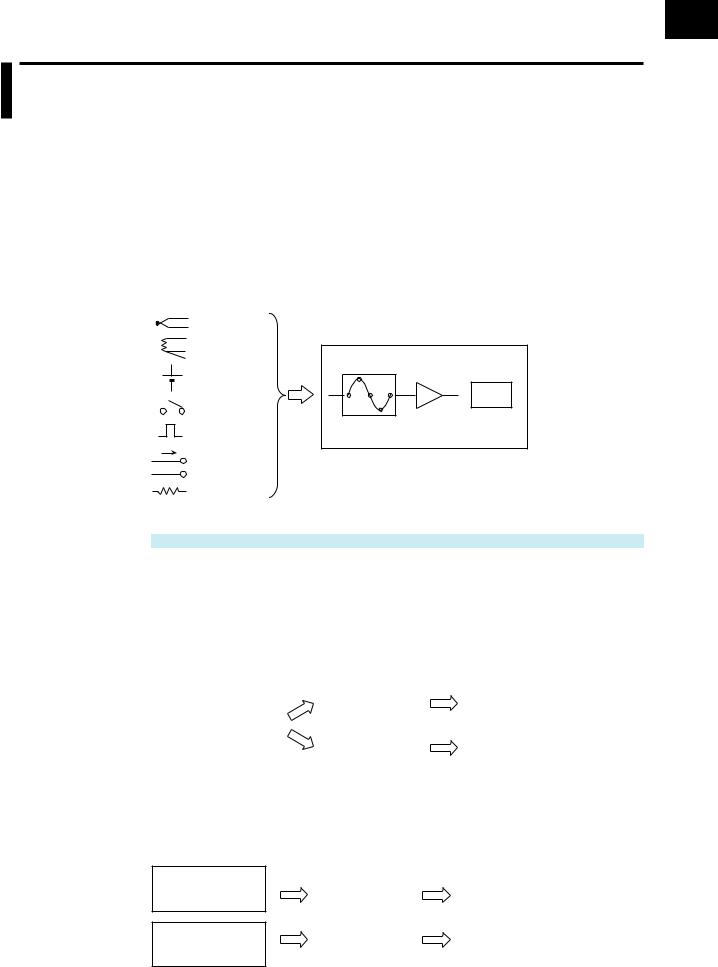
Measurement
The GX/GP can measure signals from thermocouples, RTD sensor input, DC voltage, On/ Off (voltage-free contact, level), DC current (mA), pulse input and resistance. (The input type varies depending on the module type.)
The GX/GP samples the signals received through the input modules at a specified scan interval and performs A/D conversion. These values become the measured values of each channel.
Temperature |
|
|
|
(sensor) |
|
|
|
DC voltage |
|
|
1.23 |
Contact |
|
|
|
Input |
|
|
|
|
A/D |
Measured |
|
Pulse |
Sampling |
||
|
conversion |
value |
|
I |
|
||
|
I/O module |
|
|
DC current (mA) |
|
|
|
Resistance |
|
|
|
Related Setup Items
Item |
Reference |
Scan interval |
→page 1-119 |
Recording
Data Type
The GX/GP can record two types of measured data: display data and event data (event only when the measurement mode is set to High speed or Dual interval).
Data sampled at the scan interval is recorded in the internal memory as measured data for each specified data type (display data and event data).
|
|
Display data |
|
Measured data |
|
Measured value at |
|
|
|
|
|
each scan interval |
|
|
|
|
|
|
|
Event data |
|
Measured data |
|
|
|
|
|
||
|
|
|
|
|
|
|
|
Data type |
|
Measured value at each |
|
|
|
|
|
recording interval |
|
Dual interval
When the measurement mode is Dual interval, measured data of the channels assigned to measurement groups are recorded in the internal memory by each measurement group.
Measurement group 1 Measured value at each scan interval
Measurement group 2
Measured value at each scan interval
Display data |
|
Measured data |
|
|
|
|
|
|
|
|
|
Event data |
|
Measured data |
|
|
|
|
|
Data type |
|
Measured value at each |
|
|
|
recording interval |
|
IM 04L51B01-01JA |
xiii |
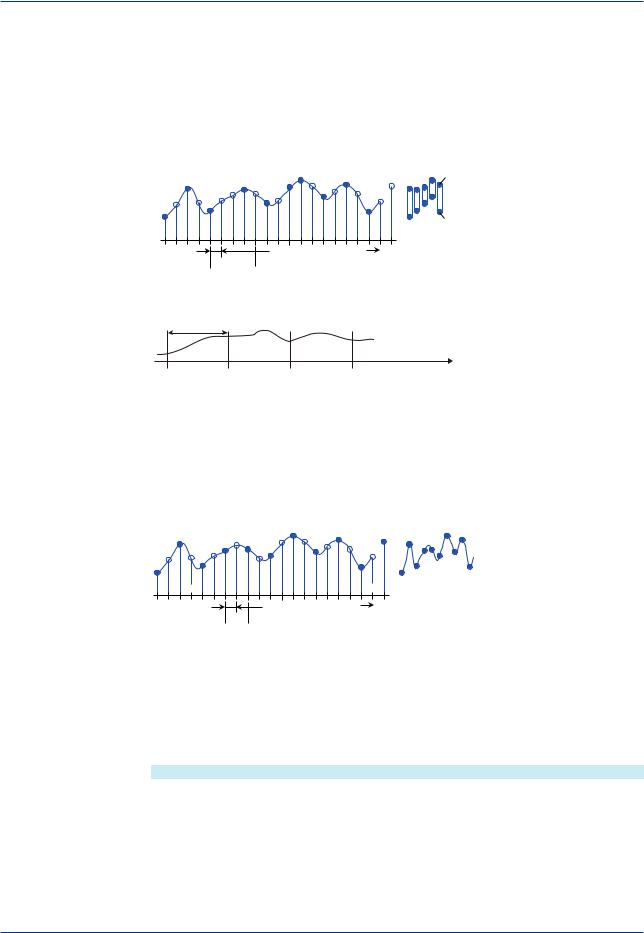
Basic Functions of the GX/GP
Display Data
Display data can be likened to recording to chart paper on conventional pen recorders. Using the data sampled at the scan interval, the GX/GP records the maximum and minimum sampling data values within each recording interval (interval determined by the trend interval [/div]). Detailed data of each sample is not retained, but because the maximum and minimum data values are recorded, display data expresses the fluctuation range in each recording interval. In addition, because the number of data values can be reduced, display data allows long-term data recording to the internal memory.
Display data recording
Recording data
|
|
Max. |
Max. |
Max. |
|
Max. |
Max. |
Max. |
|||
|
|||||
|
|
||||
|
|
Min. |
|
|
|
|
Min. |
Min. |
Min. |
Min. |
|
Min. |
|
||||
|
|
|
|
||
|
|
Scan interval |
Time |
|


 Recording interval (determined by the trend interval [/div])
The measured data of display data is divided at the interval specified by the saving interval and saved to files.
Saving interval
Time
|
|
|
|
|
|
|
|
|
|
File |
|
File |
|
File |
|
Adding data |
|
Event Data
In the case of event data, the GX/GP records the data sampled at the scan interval at the specified recording interval.
Event data can be likened to the data acquired using data loggers and the like where data is sampled at the scan interval (or recording interval). Detailed data is recorded, but the data size becomes large.
Event data recording
Recording data
Scan interval |
Time |


 Recording interval
The measured data of event data is divided at the interval determined by the data length and saved to files.
Event data can be recorded using the following recording modes.
•Free: Records data at all times
•Single: Records data when the trigger condition is met
•Repeat: Records data every time the trigger condition is met
Related Setup Items
Item |
Reference |
File type |
→page 1-125 |
Saving interval |
|
Trend interval [/div] (display data) |
→page 1-110 |
Recording interval (event data) |
→page 1-125 |
Data length |
|
Recording mode |
|
xiv
IM 04L51B01-01JA

Basic Functions of the GX/GP
Display
Measured data acquired in the internal memory can be displayed on the screen as trend waveforms, numeric values, bar graphs, and the like. In addition, in accordance with the application or the situation at the actual site, measured data can be displayed on a custom display (/CG option) that the user designs using DXA170 DAQStudio.
Trend |
Digital |
Bar graph |
Multi panel |
Custom display
Trend Display of Display Data
The GX/GP shows display data according to the specified trend interval [/div]. The trend interval is specified as the time span per division of the screen.
For example, if the screen shows 19 divisions, setting the trend interval to 1 min/div will cause the screen to display 19 minutes of data.
19 div
1 div
(1 min)
19 minutes
IM 04L51B01-01JA |
xv |

Basic Functions of the GX/GP
Trend Display of Event Data
The GX/GP shows event data according to the trend interval [/div] that is determined by the recording interval setting.
The relationship between the recording interval and trend interval [/div] is shown below.
Recording Interval and Trend Interval
Recording interval |
1ms |
2ms |
5ms |
10ms |
20ms |
50ms |
|
|
|
Trend interval |
100ms |
200ms |
500ms |
1s |
2s |
3s |
|
|
|
[/div] |
|
|
|
|
|
|
|
|
|
Recording interval |
100ms |
200ms |
500ms |
1s |
2s |
5s |
10s |
15s |
20s |
Trend interval |
5s |
10s |
15s |
30s |
1min |
150s |
5min |
450s |
10min |
[/div] |
|
|
|
|
|
|
|
|
|
Recording interval |
1min |
2min |
5min |
10min |
15min |
20min |
30min |
|
|
Trend interval |
30min |
1h |
150min |
5h |
450min |
10h |
15h |
|
|
[/div] |
|
|
|
|
|
|
|
|
|
Trend Interval and the Speed of Movement of Waveforms
The trend interval is analogous to the paper feeding speed of pen recorders and the like. The relationship between the trend interval and the speed of movement of waveforms is shown below.
GX20/GP20
Recording Interval (Trend interval) |
100ms2 |
200ms2 |
500ms2 |
1s2 |
2s2 |
3s3 |
Time corresponding to one dot (ms) |
1 |
2 |
5 |
10 |
20 |
50 |
Speed of waveform movement |
1107000 |
553500 |
221400 |
110700 |
55350 |
22140 |
(approximation in mm/h) |
|
|
|
|
|
|
|
|
|
|
|
|
|
Recording Interval (Trend interval) |
5s1 |
10s1 |
15s |
30s |
1min |
|
Time corresponding to one dot (s) |
0.1 |
0.2 |
0.5 |
1 |
2 |
|
Speed of waveform movement |
11070 |
5535 |
2214 |
1107 |
554 |
|
(approximation in mm/h) |
|
|
|
|
|
|
|
|
|
|
|
|
|
Recording Interval (Trend interval) |
2min |
5min |
10min |
15min |
20min |
|
Time corresponding to one dot (s) |
4 |
10 |
20 |
30 |
40 |
|
Speed of waveform movement |
277 |
111 |
55 |
37 |
28 |
|
(approximation in mm/h) |
|
|
|
|
|
|
|
|
|
|
|
|
|
Recording Interval (Trend interval) |
30min |
1h |
2h |
4h |
10h |
|
Time corresponding to one dot (s) |
60 |
120 |
240 |
480 |
1200 |
|
Speed of waveform movement |
18 |
9.2 |
4.6 |
2.3 |
0.9 |
|
(approximation in mm/h) |
|
|
|
|
|
|
1 50 dots per division
2 100 dots per division
3 60 dots per division
xvi
IM 04L51B01-01JA
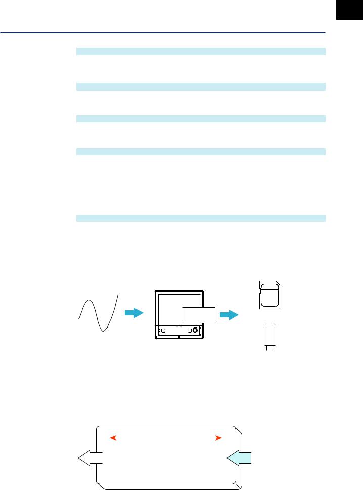
Basic Functions of the GX/GP
GX10/GP10
Recording Interval (Trend interval) |
100ms2 |
200ms2 |
500ms2 |
1s2 |
2s2 |
3s3 |
Time corresponding to one dot (ms) |
1 |
2 |
5 |
10 |
20 |
50 |
Speed of waveform movement |
653400 |
326700 |
130680 |
65340 |
32670 |
13068 |
(approximation in mm/h) |
|
|
|
|
|
|
|
|
|
|
|
|
|
Recording Interval (Trend interval) |
5s1 |
10s1 |
15s |
30s |
1min |
|
Time corresponding to one dot (s) |
0.1 |
0.2 |
0.5 |
1 |
2 |
|
Speed of waveform movement |
6534 |
3267 |
1307 |
653 |
327 |
|
(approximation in mm/h) |
|
|
|
|
|
|
|
|
|
|
|
|
|
Recording Interval (Trend interval) |
2min |
5min |
10min |
15min |
20min |
|
Time corresponding to one dot (s) |
4 |
10 |
20 |
30 |
40 |
|
Speed of waveform movement |
163 |
65 |
33 |
22 |
16 |
|
(approximation in mm/h) |
|
|
|
|
|
|
|
|
|
|
|
|
|
Recording Interval (Trend interval) |
30min |
1h |
2h |
4h |
10h |
|
Time corresponding to one dot (s) |
60 |
120 |
240 |
480 |
1200 |
|
Speed of waveform movement |
11 |
5.4 |
2.7 |
1.4 |
0.5 |
|
(approximation in mm/h) |
|
|
|
|
|
|
1 50 dots per division |
|
|
|
|
|
|
2 100 dots per division |
|
|
|
|
|
|
3 60 dots per division |
|
|
|
|
|
|
Related Setup Items
Item |
Reference |
Trend interval [/div] (display data) |
→page 1-110 |
Recording interval (event data) |
→page 1-125 |
Saving
Data files that are divided at a specific time interval (saving interval) and held in the internal memory are automatically saved to an SD memory card (when auto save is set to On). Data files can also be exported to USB flash memory.
Internal |
memory |
GX/GP |
Auto save or manual save
SD memory card
manual save
USB flash memory
Media FIFO Function
If not enough free space is available when saving a new data file to the SD memory card, files are deleted in order from the oldest data update date/time to save the new file. This operation is referred to as FIFO (first in first out).
When saving the data files automatically, you can save the data so that the most recent data files are constantly retained in the SD memory card. This method allows you to use the GX/ GP continuously without having to replace the SD memory card.
|
Old |
Update date |
|
New |
|
|||||||||
Deleted |
|
|
|
|
|
|
|
|
|
|
|
Saved |
|
|
|
|
|
|
|
|
|
|
|
|
|
|
|
||
|
|
File 1 |
|
|
File 2 |
|
|
File 3 |
|
|
|
File 4 |
||
|
|
|
|
|
|
|
|
|
|
|
|
|
|
|
|
|
|
|
|
|
|
|
|
|
|
|
|
|
|
Medium |
|
|
|
|
|
|
|
|
|
|
|
|||
IM 04L51B01-01JA |
xvii |

Basic Functions of the GX/GP
Related Setup Items
Item |
Reference |
Saving interval |
→page 1-125 |
Auto save |
→page 1-143 |
Media FIFO |
|
Data Utilization
Measurement data files can be loaded into the standard software (Universal Viewer) to display trend waveforms and values.
Moreover, data values at the cursor position can be read, statistics (maximum, minimum, P-P, average, rms) can be calculated, and so forth.
The loaded data can be converted into Excel or text format to be analyzed with other software applications or used in other ways.
Control
By installing a PID Control Module (GX90UT), you can perform PID control of up to 20 loops (up to 6 loops for the GX10/GX20-1/GP10/GP20-1). In addition to control loop monitoring and the control group screen for convenient operation, adjustment using the tuning screen is available.
Adding the /PG option to the GX/GP main unit allows 99 patterns (up to 99 segments per pattern) of program patterns to be stored in the main unit. Further, up to 32 time events and 32 PV events can be set for each segment.
xviii
IM 04L51B01-01JA
Chapter 1 Configuring the GX/GP and Viewing the Settings
Setup Guide (Read this first)
GX/GP Setup Procedure
To use the GX/GP, follow the procedure below to configure it.
Configuration flowchart
1 |
Set the measurement mode. |
|
|
2 |
Make the main unit recognize the modules. |
|
(Reconfigure the GX/GP.) |
||
|
3 |
|
Assign channel displays. |
|||
|
|
|
|
|
|
|
|
Assign automatically |
|
Assign manually |
|
|
|
|
|
|
|
|
|
|
|
|
|
Initialize
4 |
Set the date and time.1 |
|
|
5 |
Configure settings. |
Set the measurement mode according to the measurement conditions.
 Operation: 1.29.3, “Setting the Measurement Mode”
Connected expandable I/O, GM sub unit, and installed modules are identified, and the system is reconfigured. If you change the system configuration, you need to reconfigure.
 Operation: 1.29.4, “Reconfiguring the GX/GP”
To assign channel displays (display group settings) automatically, initialize.
To assign them manually, do it in “Configure settings.”
Channel displays are assigned automatically along with initialization.
 Operation: 1.29.1, “Initializing the Settings and the Internal Memory”
1 If you need to set the time zone or Daylight Saving Time (DST) or both, do so before setting the date and time.
Configure the GX/GP settings.
 See the various settings from section 1.1.
1
Settings the Viewing and GX/GP the Configuring
IM 04L51B01-01EN |
1-1 |
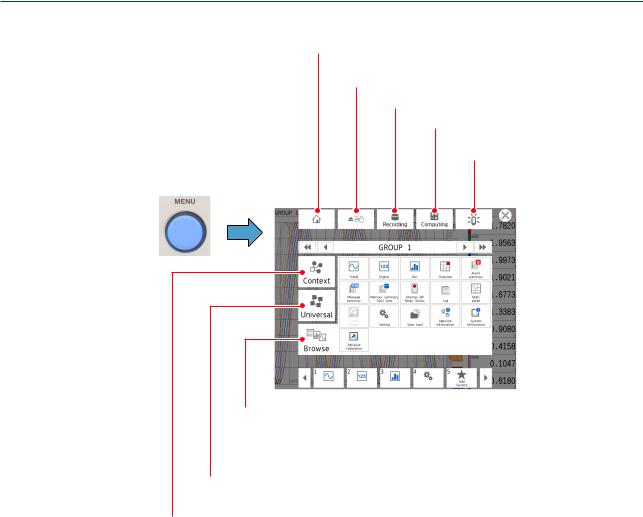
Setup Guide (Read this first)
Menu Screen
 Shows the standard (home) screen.
A screen of your choice can be assigned to the standard screen.
 Ejects storage media (SD, USB).
 Starts and stops recording.
 Starts, stops, and resets computation.
 Shows the alarm status.
MENU key |
You can acknowledge alarms. |
Menu screen
Browse tab
A screen for selecting what items are to be shown.
Select the items to be shown such as the setting menu, measurement data, and various types of information.
Common menu tab
Shows items that can be controlled globally independent of the currently displayed.
Context tab
Shows the items that can be displayed and controlled on the currently displayed screen.
The items vary depending on the displayed screen.
1-2 |
IM 04L51B01-01EN |
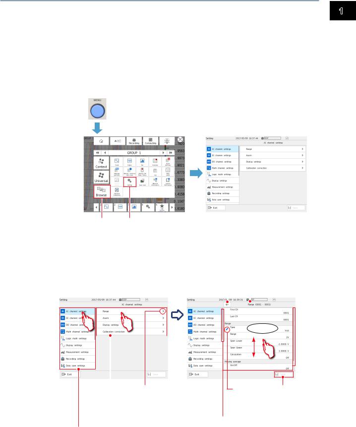
Setup Guide (Read this first)
Setting Screen
Displaying the Setting Screen
1 Press MENU.
The menu screen appears.
2 Tap the Browse tab.
3 Tap Setting.
The Setting screen appears.
1 MENU key
Menu screen |
Setting screen |
1
Settings the Viewing and GX/GP the Configuring
2 3
Basic Setting Screen Operations
When you tap an item on the setting menu shown on the left side of the screen, the corresponding setup items appear in the area on the right. When a setup item is layered, tapping the setup item shows the lower layer.
|
|
|
|
Returns to the higher level. |
||||
|
|
|
|
|||||
Setting screen |
|
|
|
|
|
|
Shows the item name |
|
|
|
|
|
|
|
|||
|
|
|
|
|
|
of the current level |
||
|
|
|
|
|
|
|
|
|
|
|
|
|
|
|
|
|
|
Flick
|
|
|
|
|
|
Indicates that there |
|
Setup item |
is a lower level. |
||
|
|
||
Shows the setup items for the item selected on the setting menu. When a setup item is layered,
Setting menu group items are displayed. A setting menu appears.
Change mark Saves the settings Appears on items whose
settings have been changed.
Scroll bar display
This appears when there are additional setting menus or setup items outside the screen display.
Flick to show the setting menus and setup items that are hidden from the screen.
IM 04L51B01-01EN |
1-3 |
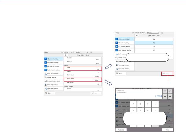
Setup Guide (Read this first)
Types of Settings
There are settings that you choose from a list or those that you enter values or character strings.
For those that you choose from a list, choose a value from the list.
For those that you need to enter a value, set the value using the displayed keyboard. Then, tap Save to save the setting.
Select from the list
Saves settings
Enter from the keyboard
1-4 |
IM 04L51B01-01EN |

Setup Guide (Read this first)
Basic GX/GP Configuration
Setup Procedure
This section explains the basic GX/GP setup items when the measurement mode is set to Normal.
In an actual setup, settings other than those shown here need to be configured depending on the usage conditions.
In addition, settings and values very depending on the measurement mode.
|
|
Setup items |
|
Main settings |
|
|
|
|
|
1 |
|
|
|
Channel settings of each module |
|
I/O channel settings |
|||
|
|
• Range |
||
|
|
|
|
• Alarm |
|
|
|
|
• Display settings |
|
|
|
|
• Calibration correction |
2 |
|
|
|
Measurement settings |
|
Measurement settings |
|||
|
|
• Scan interval |
||
|
|
|
|
• Module operation mode |
|
|
|
|
• A/D integrate |
3 |
|
|
|
Measurement data recording settings |
|
Recording settings |
|
||
|
|
• File type |
||
|
|
|
|
• Saving interval |
|
|
|
|
• Recording channel |
4 |
|
|
|
Measurement data display settings |
|
Display settings |
|||
|
|
• Trend interval |
||
|
|
|
|
• Group settings |
|
|
|
|
• Message settings |
|
|
|
|
• Trend settings |
|
|
|
|
• Screen display settings |
5 |
|
|
|
Measurement data save settings |
|
Data save settings |
|
||
|
|
• Save directory |
||
|
|
|
|
• File header |
|
|
|
|
• Data file name |
|
|
|
|
• Media save |
|
|
|
|
• File format |
1
Settings the Viewing and GX/GP the Configuring
IM 04L51B01-01EN |
1-5 |
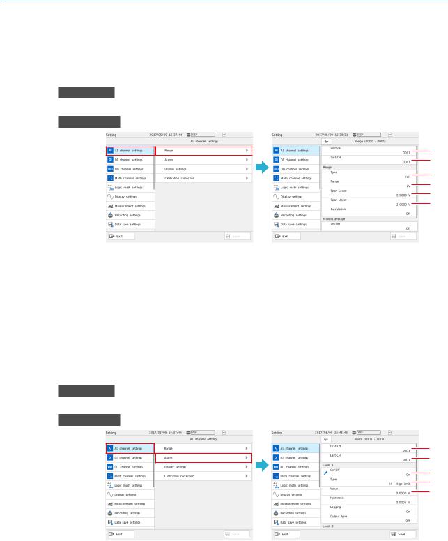
Setup Guide (Read this first)
Basic Setup
1.I/O Channel Settings (AI channel setting example)
The procedure for setting the range, display span (display range), alarm, tag display, and the like of each channel is described below.
Range Setting
Procedure
On the setting menu, tap AI channel settings and then Range.
Description
1
2
3
4
5
6
1
2
3
4
5
6
Set the first channel.1
Set the last channel.1
Set the input type.
Set the range.
Set the low limit (span lower) to be displayed.
Set the high limit (span upper) to be displayed.
1If the settings are the same for multiple channels, you can set a channel range by specifying the first channel and last channel, and configure those channels simultaneously.
Alarm Setting (Example of setting level 1)
Procedure
On the setting menu, tap AI channel settings and then Alarm.
Description
1
2
3
4
5
1
2
3
4
5
Set the first channel. Set the last channel.
Specify On to assign an alarm to Level 1.1 Set the alarm type.
Set the alarm value.
1 You can set up to four alarms (Level 1 to 4).
1-6 |
IM 04L51B01-01EN |
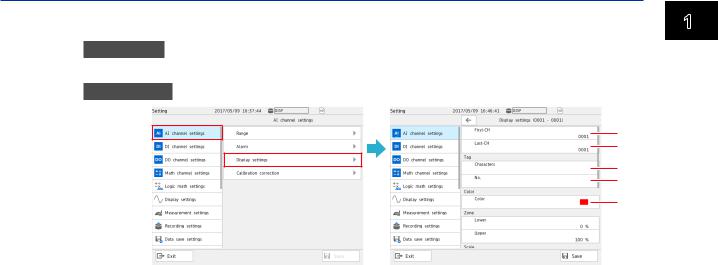
Setup Guide (Read this first)
Display Settings
Procedure
On the setting menu, tap AI channel settings and then Display settings.
Description
1
2
3
4
5
1 Set the first channel.
2 Set the last channel.
3 Set the tag characters.
4 Set the tag number.
5 Set the display color.
Numbers are displayed with higher precedence than characters. When a number is not assigned, the tag characters are displayed. If neither is set, the channel number is displayed.
1
Settings the Viewing and GX/GP the Configuring
IM 04L51B01-01EN |
1-7 |
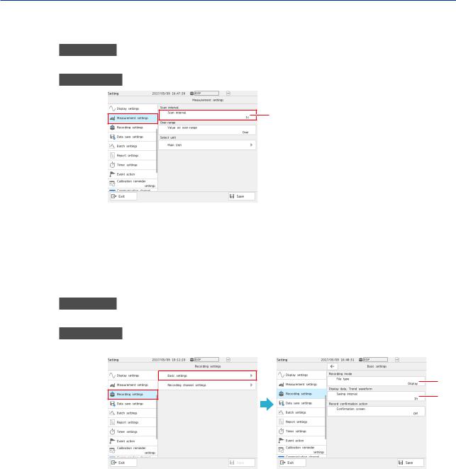
Setup Guide (Read this first)
2.Measurement Settings
Set the scan interval.
Procedure
On the setting menu, tap Measurement settings and then Scan interval.
Description
1
1 Set the scan interval.
3.Recording Settings
Specify the settings for recording measured data.
Set the recording conditions for each file type, display data and event data.
Basic Setup
Procedure
On the setting menu, tap Recording settings and then Basic settings.
Description
When the File Type Is Display Data
1
2
1
2
Tap File type and then Display.
Set the interval for saving data files of display data.
The files are divided with the interval specified here.
1-8 |
IM 04L51B01-01EN |

Setup Guide (Read this first)
When the File Type Is Event Data
1
2
3
4
1 Tap File type and then Event.
2 Set the interval for recording event data.
3 Set the mode for recording event data.
4 Set the measurement data length (per file).
Recording Channel Settings
Procedure
On the setting menu, tap Recording settings and then Recording channel settings.
Description
1
2
3
1
Settings the Viewing and GX/GP the Configuring
1
2
3
Set the channels for recording display data. Set the channels for recording event data.
Set the channels for recording manual sampled data.
IM 04L51B01-01EN |
1-9 |
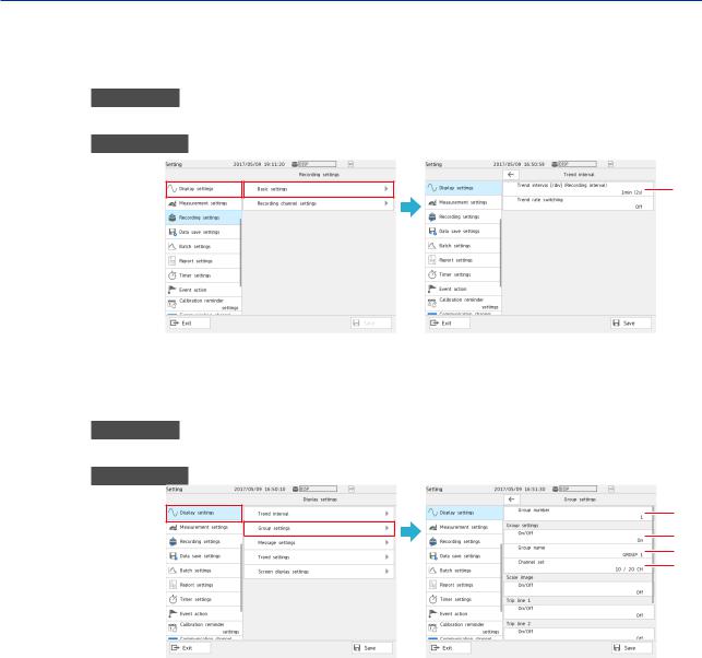
Setup Guide (Read this first)
4.Display Settings
Specify the measured waveform display settings.
Trend Interval Setting
Procedure
On the setting menu, tap Display settings and then Trend interval.
Description
1
1 Set the trend interval [/div].
Group Settings
Procedure
On the setting menu, tap Display settings and then Group settings.
Description
1
2
3
4
1
2
3
4
Set the number of the group to display.
Set this to On to use the display group of the specified display group number. Assign a group name to the display group.
Set the channels to display in the display group.
1-10 |
IM 04L51B01-01EN |
 Loading...