


 Loading...
User's
Manual
Models SE100MJ/NJ and
SE200MJ/NJ
Integral Type
Magnetic Flowmeter
IM 1E10B0-01E
IM 1E10B0-01E
10th Edition
|
|
|
|
|
CONTENTS |
|
|
|
|
|
Contents |
|
|
|
|
|
|
|
|
|
1. |
INTRODUCTION |
.............................................................................................. |
1-1 |
|||
2. |
HANDLING PRECAUTIONS .......................................................................... |
2-1 |
||||
|
|
2.1 |
Checking Model and Specifications ............................................................... |
2-1 |
||
|
|
2.2 |
Accessories ...................................................................................................... |
2-1 |
||
|
|
2.3 |
Storage Precautions ......................................................................................... |
2-1 |
||
|
|
2.4 |
Installation Location Precautions .................................................................... |
2-1 |
||
|
|
2.5 |
Cleaning Precautions ....................................................................................... |
2-2 |
||
|
|
2.6 |
Converter Reorientation Precautions .............................................................. |
2-2 |
||
3. |
INSTALLATION ................................................................................................ |
|
3-1 |
|||
|
|
3.1 |
Piping Design Precautions .............................................................................. |
3-1 |
||
|
|
3.2 |
Handling Precautions ...................................................................................... |
3-3 |
||
|
|
|
3.2.1 |
General Precautions ................................................................................. |
3-3 |
|
|
|
|
3.2.2 |
Flowmeter Piping ..................................................................................... |
3-4 |
|
|
|
3.3 |
Mounting ......................................................................................................... |
3-4 |
||
|
|
|
3.3.1 Nominal Diameter 15mm (0.5in) to 40mm (1.5in) Wafer Type .............. |
3-4 |
||
|
|
|
3.3.2 Nominal Diameter 50 mm(2in) to 200 mm(8in) Wafer Type .................. |
3-6 |
||
|
|
|
3.3.3 Nominal Diameter 15 mm (0.5in) to 200 mm (8in) Flange Type ............ |
3-8 |
||
|
|
3.4 |
Wiring Precautions ........................................................................................ |
3-10 |
||
|
|
|
3.4.1 |
Protective Grounding ............................................................................. |
3-10 |
|
|
|
|
3.4.2 |
General Precautions ............................................................................... |
3-10 |
|
|
|
|
3.4.3 Power and Output Cables ...................................................................... |
3-10 |
||
|
|
|
3.4.4 |
DC Connections ..................................................................................... |
3-11 |
|
|
|
|
3.4.5 |
Wiring Ports ........................................................................................... |
3-11 |
|
|
|
|
3.4.6 Connecting to External Instruments ...................................................... |
3-12 |
||
4. |
BASIC OPERATING PROCEDURES ............................................................ |
4-1 |
||||
|
|
4.1 |
Liquid Crystal Display (LCD) ........................................................................ |
4-1 |
||
|
|
4.2 |
Types of Display Data .................................................................................... |
4-2 |
||
|
|
|
4.2.1 The Initial Procedure to Change the Display Mode ................................ |
4-3 |
||
|
|
|
4.2.2 Flow Rate Display Mode ......................................................................... |
4-5 |
||
|
|
|
4.2.3 |
Setting Mode ............................................................................................ |
4-6 |
|
|
|
|
4.2.4 |
Alarm Display Mode ............................................................................... |
4-7 |
|
|
|
|
4.2.5 |
Auto Zero Mode ...................................................................................... |
4-8 |
|
|
|
|
4.2.6 |
Indicator Error Mode ............................................................................... |
4-8 |
|
5. |
FUNCTION AND DATA SETTINGS ............................................................. |
5-1 |
||||
|
|
5.1 |
Setting Flow Span ........................................................................................... |
5-1 |
||
|
|
5.2 |
Power Frequency (For DC Power Supply Version only) .............................. |
5-4 |
||
|
|
5.3 |
Other Functions and Settings .......................................................................... |
5-4 |
||
|
|
|
5.3.1 |
Pulse Output ............................................................................................. |
5-4 |
|
|
|
|
5.3.2 Display of Internal Totalization Values .................................................... |
5-6 |
||
|
|
|
5.3.3 Resetting for Totalization Display ........................................................... |
5-7 |
||
|
|
|
5.3.4 |
Damping Time Constant .......................................................................... |
5-8 |
|
|
|
|
5.3.5 Current Output during Alarm Occurrence ............................................... |
5-8 |
||
|
|
|
5.3.6 |
Reversing Flow Direction ........................................................................ |
5-8 |
|
FD No. IM 1E10B0-01E |
|
|
|
|
||
10th Edition: Apr. 2002 (YK) |
|
|
|
|
||
All Rights Reserved, Copyright © 1999, Yokogawa Electric Corporation |
|
|
||||
|
|
|
|
i |
IM 1E10B0-01E |
|
|
|
CONTENTS |
5.3.7 |
Limiting Current Output .......................................................................... |
5-9 |
5.3.8 |
Forward and Reverse Flow Measurement ............................................. |
5-10 |
5.3.9 |
Automatic Two Range Switching .......................................................... |
5-11 |
5.3.10 |
Alarm Output at Low Flow Limit (Flow Switch) .................................. |
5-12 |
5.3.11 |
Totalization Switch Output .................................................................... |
5-13 |
5.3.12 |
Alarm Output ......................................................................................... |
5-14 |
5.3.13 |
Data Settings Enable / Inhibit ................................................................ |
5-14 |
5.3.14 |
Procedure of Selecting Special Application Items ................................. |
5-15 |
5.3.15 |
Rate Limit .............................................................................................. |
5-15 |
6. |
OPERATION VIA BRAIN TERMINAL (BT200) ......................................... |
6-1 |
||
|
6.1 |
BT200 Connections ......................................................................................... |
6-1 |
|
|
6.2 |
BT200 Keypad Layout .................................................................................... |
6-2 |
|
|
6.3 |
BT200 Key Functions ..................................................................................... |
6-3 |
|
|
6.4 |
Displaying Flow Rate Data ............................................................................. |
6-4 |
|
|
6.5 |
Setting Parameters ........................................................................................... |
6-5 |
|
|
|
6.5.1 |
Setting Flow Span .................................................................................... |
6-5 |
|
|
6.5.2 Power Frequency (For DC version only) ................................................. |
6-7 |
|
|
6.6 |
Other Functions ............................................................................................... |
6-7 |
|
|
|
6.6.1 |
User-Defined Units .................................................................................. |
6-7 |
|
6.7 |
Other Important Points .................................................................................... |
6-8 |
|
7. |
OPERATION VIA HART COMMUNICATOR ............................................ |
7-1 |
||
|
7.1 |
Conditions of Communication Line ............................................................... |
7-1 |
|
|
|
7.1.1 Interconnection between ADMAG SE and HART Communicator ......... |
7-1 |
|
|
|
7.1.2 |
Communication Line Requirements ........................................................ |
7-2 |
|
7.2 |
Basic Operation of the HART Communicator (Model 275) .......................... |
7-3 |
|
|
|
7.2.1 |
Keys and Functions .................................................................................. |
7-3 |
|
|
7.2.2 |
Display ..................................................................................................... |
7-4 |
|
|
7.2.3 |
Calling Up Menu Addresses .................................................................... |
7-4 |
|
|
7.2.4 Entering, Setting and Sending Data ......................................................... |
7-6 |
|
|
7.3 |
Parameters ....................................................................................................... |
7-8 |
|
|
|
7.3.1 |
Parameters Configuration ........................................................................ |
7-8 |
|
|
7.3.2 |
Data Renewing ......................................................................................... |
7-8 |
|
|
7.3.3 |
Menu Tree ................................................................................................ |
7-9 |
|
|
7.3.4 |
Setting Parameters ................................................................................. |
7-12 |
8. |
ACTUAL OPERATION .................................................................................... |
8-1 |
|
|
8.1 |
Pre-Operation Zero Adjustment ...................................................................... |
8-1 |
|
|
8.1.1 Zero Adjustment Using Data Setting Keys .............................................. |
8-1 |
|
|
8.1.2 Zero Adjustment Using BT200 ................................................................ |
8-2 |
|
|
8.1.3 Zero Adjustment Using HART Communicator ....................................... |
8-3 |
|
8.2 |
Self-diagnostics Functions .............................................................................. |
8-4 |
|
|
8.2.1 Output Status during Alarm Occurrence .................................................. |
8-4 |
|
|
8.2.2 Self-diagnostics Using HART Communicator ........................................ |
8-5 |
|
|
8.2.3 Error Description and Countermeasure ................................................... |
8-6 |
9. |
MAINTENANCE ................................................................................................ |
9-1 |
|
|
9.1 Loop Test (Test output) .................................................................................. |
9-1 |
|
|
9.1.1 ................................... |
Settings for Test Output Using Data Setting Keys |
9-1 |
|
9.1.2 ...................................................... |
Setting for Test Output Using BT200 |
9-2 |
ii |
IM 1E10B0-01E |
|
|
|
|
CONTENTS |
|
9.1.3 Setting for Test Output Using HART Communicator ............................. |
9-3 |
||
|
9.2 |
Trouble Shooting ............................................................................................. |
9-5 |
|
|
9.2.1 |
No Indication ........................................................................................... |
9-5 |
|
|
9.2.2 |
Unstable Zero ........................................................................................... |
9-6 |
|
|
9.2.3 Disagreement of Indication with Actual Flow Rate ................................. |
9-7 |
||
10. |
OUTLINE .......................................................................................................... |
|
|
10-1 |
11. |
PARAMETER LIST ........................................................................................ |
11-1 |
||
|
11.1 |
Parameters for ADMAG SE Indicator and BRAIN Terminal ..................... |
11-1 |
|
|
11.2 |
Parameters for HART Communicator .......................................................... |
11-7 |
|
12. |
EXPLOSION PROTECTED TYPE INSTRUMENT .................................. |
12-1 |
||
|
12.1 |
CENELEC ATEX(KEMA) ........................................................................... |
12-1 |
|
|
12.2 |
FM |
................................................................................................................. |
12-2 |
|
12.3 |
CSA ............................................................................................................... |
12-2 |
|
|
12.4 |
SAA ............................................................................................................... |
12-3 |
|
13. |
PRESSURE EQUIPMENT ......................................................DIRECTIVE |
13-1 |
||
iii |
IM 1E10B0-01E |

1. INTRODUCTION
1.INTRODUCTION
This instrument has been already adjusted at the factory before shipment.
To ensure correct use of the instrument, please read this manual thoroughly and fully understand how to operate the instrument before operating it.
Regarding This Manual
•This manual should be passed on to the end user.
•Before use, read this manual thoroughly to comprehend its contents.
•The contents of this manual may be changed without prior notice.
•All rights reserved. No part of this manual may be reproduced in any form without Yokogawa’s written permission.
•Yokogawa makes no warranty of any kind with regard to this material, including, but not limited to, implied warranties of merchantability and suitability for a particular purpose.
•All reasonable effort has been made to ensure the accuracy of the contents of this manual. However, if any errors are found, please inform Yokogawa.
•Yokogawa assumes no responsibilities for this product except as stated in the warranty.
•If the customer or any third party is harmed by the use of this product, Yokogawa assumes no responsibility for any such harm owing to any defects in the product which were not predictable, or for any indirect damages.
Safety Precautions
•The following general safety precautions must be observed during all phases of operation, service, and repair of this instrument. Failure to comply with these precautions or with specific WARNINGS given elsewhere in this manual violates safety standards of design, manufacture, and intended use of the instrument. YOKOGAWA Electric Corporation assumes no liability for the customer’s failure to comply with these requirements. If this instrument is used in a manner not specified in this manual, the protection provided by this instrument may be impaired.
The following safety symbol marks are used in this manual and instrument;
WARNING
A WARNING sign denotes a hazard. It calls attention to procedure, practice, condition or the like, which, if not correctly performed or adhered to, could result in injury or death of personnel.
CAUTION
A CAUTION sign denotes a hazard. It calls attention to procedure, practice, condition or the like, which, if not correctly performed or adhered to, could result in damage to or destruction of part or all of the product.
IMPORTANT
A IMPORTANT sign denotes an attention to avoid leading to damage to instrument or system failure.
NOTE
A NOTE sign denotes a information for essential understanding of the operation and features.
Protective grounding terminal.
Function grounding terminal. This terminal should not be used as a “Protective grounding terminal”.
Alternating current.
Direct current.
1-1 |
IM 1E10B0-01E |

Warranty
•The guaranteed term of this instrument is described in the quotation. We repair the damages that occurred during the guaranteed term for free.
•Please contact with our sales office when this instrument is damaged.
•If the instrument has trouble, please inform us model code, serial number, and concrete substances or situations. It is preferable to be attached a outline or data.
•We decide after the examination if free repair is available or not.
•Please consent to the followings for causes of damages that are not available as free repair, even if
it occured during the guaranteed term.
A:Unsuitable or insufficient maintenance by the customer.
B:The handling, using, or storage that ignore the design and specifications of the instrument.
C:Unsuitable location that ignore the description in this manual.
D:Remaking or repair by a person except whom we entrust.
E:Unsuitable removing after delivered.
F:A natural disaster (ex. a fire, earthquake, storm and flood, thunderbolt) and external causes.
For Safety Using
For safety using the instrument, please give attention mentioned below.
WARNING
(1) Installation
•The instrument must be installed by expert engineer or skilled personnel. The procedures described about INSTALLATION are not permitted for operators.
•The Magnetic Flow Tube is a heavy instrument. Please give attention to prevent that persons are injured by carrying or installing. It is preferable for carrying the instrument to use a cart and be done by two or more persons.
•In case of high process temperature, care should be taken not to burn yourself because the surface of body and case reach a high temperature.
•When removing the instrument from hazardous processes, avoid contact with the fluid and the interior of the flow tube.
•All installation shall comply with local installation requirement and local electrical code.
1. INTRODUCTION
(2) Wiring
•The instrument must be installed by expert engineer or skilled personnel. The procedures described about WIRING are not permitted for operators.
•Please confirm voltages between the power supply and the instrument before connecting the power cables. And also, please confirm that the cables are not powered before connecting.
•The protective grounding must be connected to
the terminal  in order to avoid personal shock hazard.
(3) Operation
•Wait 10 min. after power is turned off, before opening the covers.
(4) Maintenance
•Please do not carry out except being written to a maintenance descriptions. When these procedures are needed, please contact to nearest YOKOGAWA office.
•Care should be taken to prevent the build up of drift, dust or other material on the display glass and data plate. In case of its maintenance, soft and dry cloth is used.
(5) Explosion Protected Type Instrument
•For explosion proof type instrument, the description in Chapter 12 “EXPLOSION PROTECTED TYPE INSTRUMENT” is prior to the other description in this user's manual.
•Only trained persons use this instrument in the industiral location.
•The protective grounding  must be connected to a suitable IS grounding system.
•Take care not to generate mechanical spark when access to the instrument and peripheral devices in hazardous locations.
(6) The Instrument in Compliance with PED
•For the instrument in compliance with PED, the description in Chapter 13 “PRESSURE EQUIPMENT DIRECTIVE” is prior to the other description in this User’s Manual.
1-2 |
IM 1E10B0-01E |
2. HANDLING PRECAUTIONS
2.HANDLING PRECAUTIONS
This instrument has been already tested thoroughly at the factory. When the instrument is delivered, please check externals and make sure that no damage occurred during transportation.
In this chapter, handling precautions are described. Please read this chapter thoroughly at first. And please refer to the relative matter about other ones.
If you have any problems or questions, please make contact with Yokogawa sales office.
2.2 Accessories
When the instrument is delivered, please make sure that the following accessories are in the package.
•Centering device 1-set (for wafer type)
•Hexagonal wrench 1-piece (for special screw of terminal cover)
•Data Sheet 1-sheet
•Unit Labels 1-sheet
•Plug 1-piece (only for DC power supply version)
2.1Checking Model and Specifications
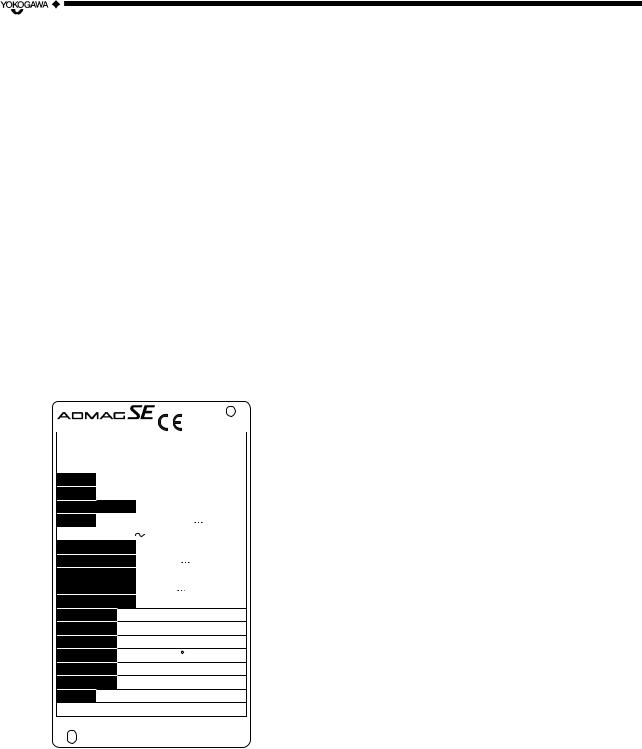
The model and specifications are shown on the Data Plate. Please confirm the specifications between the instrument that was delivered and the purchase order (refer to the chapter 5. Outline).
Please let us know Model and Serial No. when making contact with Yokogawa sales office.
MAGNETIC FIOWMETER |
0038 |
|||||||
MODEL |
|
|
|
|
|
|
|
|
SUFFIX |
|
|
|
|
|
|
|
|
|
|
|
|
|
|
|
|
|
STYLE |
|
|
|
|
|
|
|
|
|
|
|
|
|
|
|
|
|
SIZE |
mm |
|
|
|
|
|
||
METER FACTOR |
|
|
|
|
|
|
|
|
SUPPLY |
V DC |
|
10Wmax. |
|||||
|
||||||||
|
V AC |
47Hz to 63Hz 10Wmax. |
||||||
FULL SCALE |
|
|
|
|
|
|
|
|
CURRENT OUTPUT |
4-20mA |
|
|
(600Ωmax.) |
||||
|
|
|||||||
PULSE OUTPUT |
|
|
|
|
|
|
|
|
|
|
30V DC |
|
|
|
0.2mAmax. |
||
|
|
|
|
|
||||
LINING MATERIAL |
PFA |
|
|
|
|
|
||
ELECTRODE
FLUID TEMP. - 40 to +130 C (SEE IM)
FLUID PRESS. - 0.1 MPa MIN. (SEE IM)
AMB. TEMP. - 20 to +60 C SEE IM
ENCLOSURE IP 67
TAG NO.
NO.
IM : User’s Manual
Made in Japan |
N200 |
Figure 2.1 |
Data Plate |
2.3 Storage Precautions
In case the instrument is expected to be stored over a long term, please give attention to the followings;
•The instrument should be stored in its original packing condition.
•The storage location should be selected according to the following conditions:
1)The location where it is not exposed to rain or water.
2)The location where there is few vibration or shock.
3)Temperature and humidity should be: Temperature: –40 to 70˚C (–40 to 158˚F) Humidity: 5 to 80% RH (no condensation) Preferable ambient temperature and humidity are 25˚C(77˚F) and about 65% RH.
2.4Installation Location Precautions
Please select the installation location considering the following items to ensure long term stable operation of the flow tube.
•Ambient Temperature:
Please avoid to install the instrument at the location where temperature changes continuously. If the location receives radiant heat from the plant, provide heat insulation or improve ventilation.
•Atmospheric Condition:
Please avoid to install the instrument in an corrosive atmosphere. In case of installing in the corrosive atmosphere, please keep ventilating sufficiently and prevent rain from entering the conduit.
•Vibration or shock:
Please avoid to install the instrument at the location where there is heavy vibration or shock.
2-1 |
IM 1E10B0-01E |
2. HANDLING PRECAUTIONS
2.5 Cleaning Precautions
Care should be taken to prevent the buildup of dirt, dust or other material on the display glass. Such buildup may interfere with the operation of programming keys.
2.6Converter Reorientation Precautions
Please do not change the converter orientation at the customer’s site. If the converter reorientation is required, please contact Yokogawa office or service center.
2-2 |
IM 1E10B0-01E |
3. INSTALLATION
3.INSTALLATION
WARNING
This instrument must be installed by expert engineer or skilled personnel. The procedures described in this chapter are not permitted for operators.
5 D or more 2 D or more |
10 D or more |
Gate valve fully open |
Expander pipe |
5 D or more |
5 D or more |
10 D or more |
Tee |
90° bend |
Various types of valves |
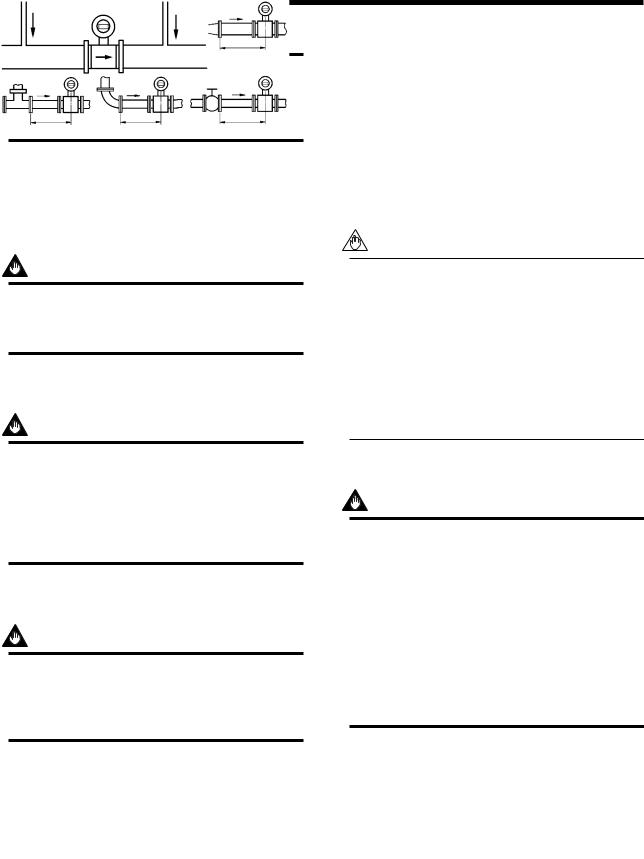
3.1Piping Design Precautions
D: Internal diameter of flowmeter |
F0301.EPS |
Figure 3.1.1 Minimum Length of Required Straight Run
NOTE
IMPORTANT
Please design the correct piping referring to the followings to prevent damage for flow tube and to keep correct measuring.
(1) Location
IMPORTANT
Please install the flow tube to the location where it is not exposed to direct sunlight and ambient temperature is –20 to + 60°C (–4 to 140°F)*.
*The minimum temperature is –10°C (14°F) in case of the 40mm or lager sizes with the carbon steel flange connection or wafer connection.
(2) Noise Rejection
IMPORTANT
The instrument should be installed away from large electrical motors, transformers and other power sources in order to avoid interference with the measurement.
(3) Length of Straight Run
To keep accurate measuring, JIS B7554 “Electro Magnetic Flow Tubes” explains about upstream piping condition of Magnetic Flowmeters.
We recommend to our customers about the piping conditions shown in Figure 3.1.1 based on JIS B7554 and our piping condition test data.
1.Nothing must be inserted or installed in the metering pipe that may interfere with the magnetic field, induced signal voltages, and flow velocity distribution.
2.These straight runs may not be required on the downstream side of flowmeter. However, if the downstream valve or other fittings cause channeling on the upstream side, provide a straight run of 2 D to 3 D on the downstream side.
(4)Liquid Conductivity
IMPORTANT
Please avoid to install the flow tube at location where liquid conductivity is likely to be nonuniform. Because it is possible to have bad influences to the flow indication by non-uniform conductivity when a chemical liquid is injected from upstream side close to the flow tube. When this occurs, it is recommended that chemical application ports are installed on the downstream side of the flow tube. In case chemicals must be added upstream side, please keep the pipe length enough so that liquid is properly mixed.
(BAD) |
(GOOD) |
Upstream side |
Downstream side |
F0302.EPS
Figure 3.1.2 Chemical Injection
3-1 |
IM 1E10B0-01E |
(5) Liquid Sealing Compound
IMPORTANT
Please give attention in using Liquid Sealing Compound to the piping, because it brings bad influences to measurement by flowing out and cover the surfaces of electrode and earth-ring.
(6) Service Area
Please select the location where there is enough area to service installing, wiring, overhaul, etc.
(7) Bypass Line
It is recommended to install the Bypass Line to facilitate maintenance and zero adjustment.
Bypass valve
Block valve
Block valve |
F0303.EPS |
Figure 3.1.3 Bypass Line
(8) Supporting the Flowmeter
CAUTION
Please avoid to support only the flowmeter, but fix pipes at first and support the flowmeter by pipes to protect the flow tube from forces caused by vibration, shock, expansion and contraction through piping.
(9) Piping Condition
IMPORTANT
The piping should be designed so that a full pipe is maintained at all times to prevent loss of signal and erroneous readings.
Please design the piping that a fluid is always filled in the pipes. The Vertical Mounting is effective for fluids that is easily separate or slurry settles within pipes.
In this case, please flow a fluid from bottom to up.
3. INSTALLATION
(GOOD) |
(BAD) |
(GOOD) |
(BAD) |
|
|
|
h |
|
|
|
h > 0 |
|
h |
|
|
|
h > 0 |
|
|
Horizontal mounting Vertical mounting
F0304.EPS
Figure 3.1.4 Filling the Pipe with Liquid
(10) No Air Bubbles
IMPORTANT
Please give attention to prevent bad influences or measuring errors from air bubbles that gathers inside measuring pipes.
In case the fluid includes air bubbles, please design the piping that prevent to gather air bubbles. In case valves are installed upstream of the flow tube, it is possible that a valve causes air bubbles, please install the flowmeter upstream side of a valve.
F0305.EPS
Figure 3.1.5 Avoiding Air Bubbles
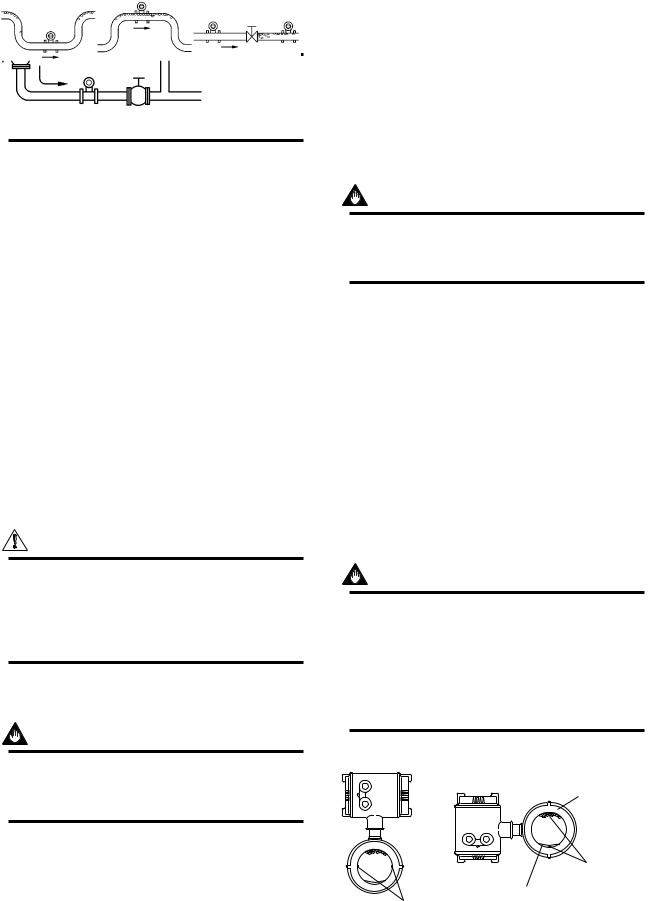
(11) Mounting Direction
IMPORTANT
When the electrodes are vertical to ground, the electrode is covered with air bubbles at upper side or slurry at downside, and it may cause the measuring errors.
Please be sure to mount the terminal box upper side of piping to prevent water penetration into terminal box.
(GOOD) |
(BAD) |
Air Bubbles
Electrodes
Slurry
Electrodes
F0306.EPS
Figure 3.1.6 Mounting Direction
3-2 |
IM 1E10B0-01E |
(12) Grounding
IMPORTANT
Improper grounding can have an adverse affect on the flow measurement. Please ensure that the instrument is properly grounded.
The electromotive force of the magnetic flow tube is minute and it is easy to be affected by noise. And also that reference electric potential is the same as the measuring fluid potential. Therefore, the reference electric potential (terminal potential) of the Flow Tube and the Converter/Amplifier also need to be the same as the measuring fluid. And moreover, that the potential must be the same with ground.
Please be sure to ground according to Figure 3.1.7.
600 V vinyl insulated electric cable
(2mm2 or larger)
Note: See “3.4.1 Protective grounding” for information on protective grounding.
Earth ring
Grounding resistance 100Ω or less
In case earth rings are used. In case earth rings are not used. (Available only for metal piping)
F0307.EPS
Figure 3.1.7 Grounding
3.2 Handling Precautions
WARNING
The Magnetic Flowmeter is a heavy instrument. Please be careful to prevent persons from injuring when it is handled.
3. INSTALLATION
CAUTION
In case the Magnetic Flow Tube without eye-bolt lifts up, please refer to Figure 3.2.1. Please never lift up by using a bar through the flow tube. It damages liner severely.
F0308.EPS
Figure 3.2.1 Vertical Lifting Sling Rigging Method
(2) Precaution for Shock
CAUTION
Care should be taken not to drop the flow tube or subject it to excessive shock. This may lead to liner damage which will cause inaccurate readings.
(3) Flange Protection Covers
IMPORTANT
Please keep the protection cover (ex. corrugated paper or anything possible to protect) attached with flange except when mounting to the pipe.
(4) Terminal Box Cover
IMPORTANT
Please never leave the terminal box cover open until wiring to prevent insulation deterioration.
3.2.1General Precautions
(1) Precaution for Carrying
The Magnetic Flowmeter is packed tightly. When it is unpacked, please give attention to prevent damages to the flowmeter. And to prevent the accident during carry to the installing location, please carry it near the location keeping packed as it delivered.
NOTE
The terminal box cover is locked by special screw. In case of opening the terminal box cover, please use the Hexagonal Wrench attached.
3-3 |
IM 1E10B0-01E |
3. INSTALLATION
CAUTION
Be sure to lock the cover with the special screw using the Hexagonal Wrench attached after tightening the terminal box cover.
(5) Long-term Non-use
IMPORTANT
It is not preferable to leave the flowmeter for long term non-use after installation.
In case the flow tube is compelled to do that, please take care of the flowmeter by the followings.
•Confirmation of Sealing Condition for the Flowmeter.
Please confirm the sealing conditions of the terminal box screw and wiring ports.
In case of the Conduit Piping, please provide the drain plugs or waterproof glands to it to prevent that moisture or water penetrates into the flow tube through the conduit.
•Regular Inspections
Please inspect the sealing condition (as above mentioned) and inside of the terminal box. And when it is suspect that water penetration into the inside flow tube (ex. rain fall), please inspect when it happened.
3.2.2Flowmeter Piping
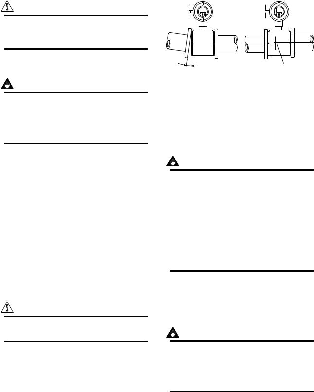
CAUTION
Mis-aligned or slanted piping can lead to leakage and damage to flanges.
•Please correct mis-alignment or slanted piping and improper distance between mounting flanges before install the flowmeter. (Please refer to Figure 3.2.2)
•Inside a pipeline which is newly installed, some foreign substances (such as welding scrap or wood chips) may exist. Please remove them by flushing piping before mounting the flowmeter.
Slant |
Mis-alignment |
F0309.EPS |
Figure 3.2.2 Slant and Mis-alignment of Flowmeter Piping
3.3 Mounting
3.3.1Nominal Diameter 15mm (0.5in) to 40mm (1.5in) Wafer Type
IMPORTANT
Please use appropriate bolts and nuts according to process connection. In case stud type of through bolts are used, be sure outside diameter of a shank is smaller than a thread ridge’s one. Please use compressed non-asbestos fiber gasket, PTFE gasket or the gasket which has equal elasticity. In case of optional code/FRG, please use rubber gasket or others which has equal elasticity. Be sure the inner diameter of the gasket does not protrude to inner piping. (Refer to Table 3.3.6)
(1) Mounting Direction
Please mount the Magnetic Flowmeter matching the flow direction of the fluid to be measured with the direction of the arrow mark on the flowmeter.
IMPORTANT
If it is impossible to match the direction, please never remodel by changing direction of the terminal box. In case the measuring fluid flows against the arrow direction, please refer to the section 5.3.6 Reversing Flow Direction.
(2) Mounting Centering Devices
To keep concentricity of the Flow Tube with pipes, please mount centering devices on the Mini-Flanges of the Flow Tube. Please give attention to the nominal diameter and flange rating of the centering devices.
3-4 |
IM 1E10B0-01E |
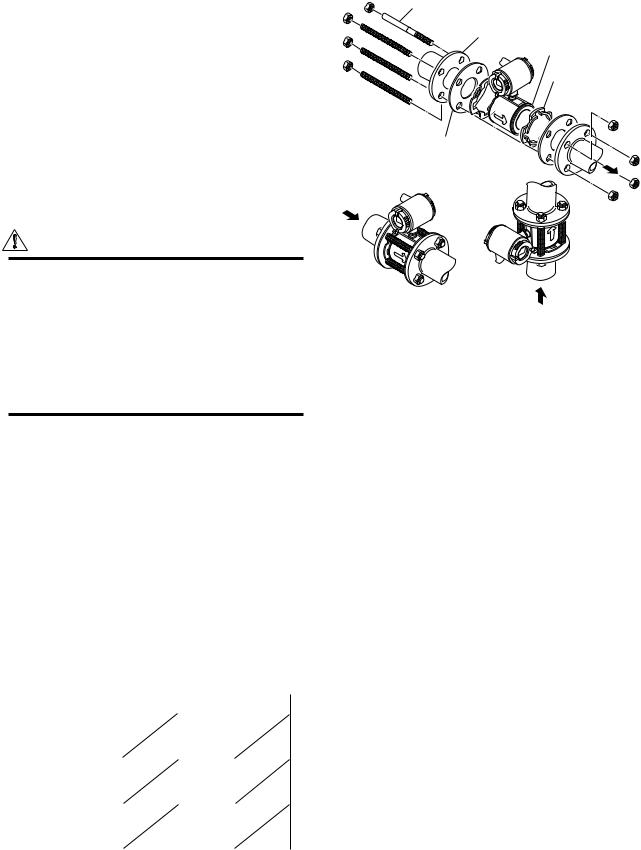
(3) Positioning Flow Tube
Please pass two through-bolts to adjacent holes of both flanges and mount the Flow Tube, and pass other through-bolts to other holes. (Refer to Figure 3.3.1) In case stud type of through-bolts are used, position them coming in contact centering devices with thread of bolts.
(4) Tightening Nuts
Please tighten the bolts according to Torque Values in Table 3.3.1. In case of PVC piping, please select optional code /FRG, use rubber gasket and tighten with the torque value in Table 3.3.2.
CAUTION
As the lining material is Fluorocarbon PFA, it is possible that nuts may loose by its character as time passes. Please tighten the nuts regularly.
Please be sure to tighten the bolts following prescribed torque values. Please tighten the flange bolts diagonally with the same torque values, step by step up to the prescribed torque value.
3. INSTALLATION
Through-Bolt  and nut
Gasket
Please use appropriate bolts and nuts according to process connection.
Flange
Mini-Flange
Centering Device 2-piece
Horizontal Mounting |
Vertical Mounting |
F0310.EPS |
Figure 3.3.1 Mounting Procedure (Size: 15 mm(0.5in) to 40 mm(1.5in))
Table 3.3.1 Tightening Torque Values for Metal Piping in N-m{kgf-cm}[in-lbf]
Size mm(inch) |
JIS 10K |
JIS 20K |
ANSI 150 |
|
ANSI 300 |
DIN PN40 |
|
||||||||||
|
|
|
|
|
|
|
|
|
|
|
|
|
|
|
|
|
|
15(0.5) |
4.5 |
- |
6.5 |
4.5 |
- 6.5 |
|
5.0 |
- 7.0 |
|
5.0 |
- 7.0 |
5.0 |
- 6.5 |
|
|||
|
{46 |
- |
66} |
{46 |
- 66} |
|
{51 |
- 71} |
|
{51 |
- 71} |
{51 |
- 66} |
|
|||
|
[40 |
- |
58] |
[40 |
- 58] |
|
[44 |
- 62] |
|
[44 |
- 62] |
[44 |
- 58] |
|
|||
|
|
|
|
|
|
|
|
|
|
|
|
|
|
|
|
|
|
25(1) |
14.5 |
- |
19.0 |
14.5 |
- 19.0 |
|
12.0 |
- 15.0 |
|
14.5 |
- 19.0 |
12.5 |
- 14.0 |
|
|||
|
{148 |
- |
194} |
{148 |
- 194} |
|
{122 |
- 153} |
|
{148 |
- 194} |
{128 |
- 143} |
|
|||
|
[128 |
- |
168] |
[128 |
- 168] |
|
[106 |
- 133] |
|
[128 |
- 168] |
[111 |
- 124] |
|
|||
|
|
|
|
|
|
|
|
|
|
|
|
|
|
|
|
|
|
40(1.5) |
26.0 |
- |
31.0 |
26.0 |
- 31.0 |
|
22.0 |
- 25.0 |
|
30.0 |
- 37.0 |
28.5 |
- 31.0 |
|
|||
|
{265 |
- |
316} |
{265 |
- 316} |
|
{224 |
- 255} |
|
{311 |
- 377} |
{291 |
- 316} |
|
|||
|
[230 - 274] |
[230 - 274] |
|
[195 - 221] |
|
[270 - 327] |
[252 - 274] |
|
|||||||||
|
|
|
|
|
|
|
|
|
|
|
|||||||
*Please use compressed non-asbestos fiber gasket, PTFE gasket or the gasket which has equal elasticity. |
T0301.EPS |
||||||||||||||||
Table 3.3.2 |
Tightening Torque Values for PVC Piping in N-m{kgf-cm}[in-lbf] |
|
|
|
|||||||||||||
|
|
|
|
|
|
|
|
|
|
|
|
||||||
Size mm(inch) |
JIS 10K |
|
JIS 20K |
ANSI 150 |
|
ANSI 300 DIN PN40 |
|
|
|
|
|
||||||
|
|
|
|
|
|
|
|
|
|
|
|
|
|
|
|
|
|
15(0.5) |
1.3 |
|
|
|
|
|
1.3 |
|
|
|
1.3 |
|
|
|
|
|
|
|
{13} |
|
|
|
|
|
{13} |
|
|
|
{13} |
|
|
|
|
|
|
|
[12] |
|
|
|
|
|
[12] |
|
|
|
[12] |
|
|
|
|
|
|
|
|
|
|
|
|
|
|
|
|
|
|
|
|
|
|
|
|
25(1) |
3.5 |
|
|
|
|
|
2.8 |
|
|
|
2.7 |
|
|
|
|
|
|
|
{36} |
|
|
|
|
|
{29} |
|
|
|
{28} |
|
|
|
|
|
|
|
[31] |
|
|
|
|
|
[25] |
|
|
|
[24] |
|
|
|
|
|
|
|
|
|
|
|
|
|
|
|
|
|
|
|
|
|
|
|
|
40(1.5) |
5.7 |
|
|
|
|
|
4.6 |
|
|
|
5.7 |
|
|
|
|
|
|
|
{58} |
|
|
|
|
|
{47} |
|
|
|
{58} |
|
|
|
|
|
|
|
[50] |
|
|
|
|
|
[41] |
|
|
|
[50] |
|
|
|
|
|
|
|
|
|
|
|
|
|
|
||||||||||
*Please select optional code /FRG and use rubber gasket or others which has equal elasticity. |
T0302.EPS |
|
|||||||||||||||
3-5 |
IM 1E10B0-01E |
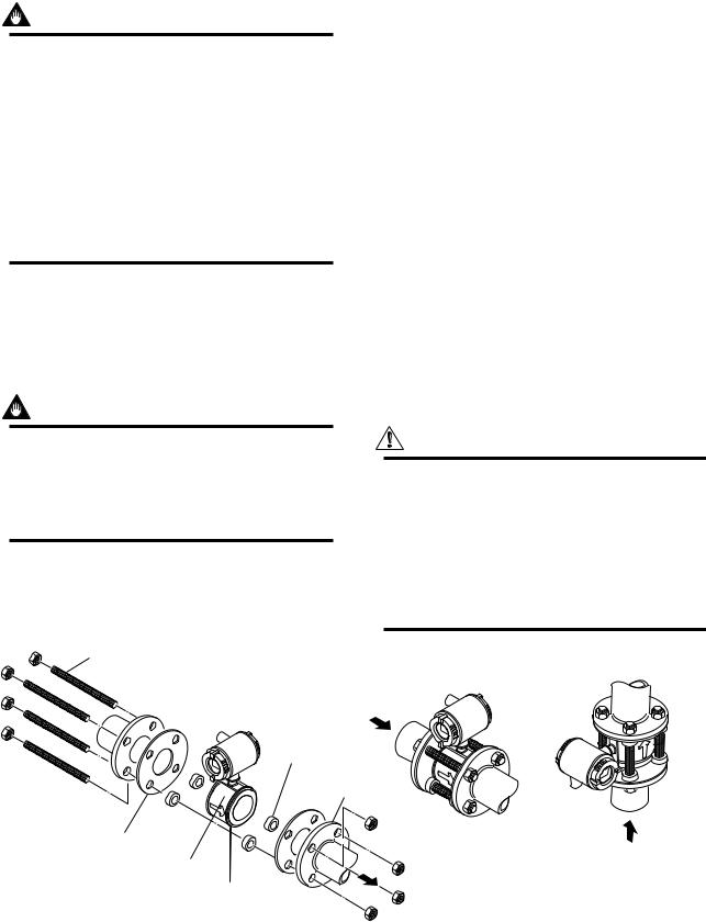
3.3.2Nominal Diameter 50 mm(2in) to 200 mm(8in) Wafer Type
IMPORTANT
Please use appropriate bolts and nuts according to process connection. In case stud type of through bolts are used, be sure outside diameter of a shank is smaller than a thread ridge’s one. Please use compressed non-asbestos fiber gasket, PTFE gasket or the gasket which has equal elasticity. In case of optional code/FRG, please use rubber gasket or others which has equal elasticity. Be sure the inner diameter of the gasket does not protrude to inner piping. (Refer to Table 3.3.6)
(1) Mounting Direction
Please mount the Magnetic Flowmeter matching the flow direction of the fluid to be measured with the direction of the arrow mark on the flowmeter.
IMPORTANT
If it is impossible to match the direction, please never remodel to change direction of the terminal box. In case the measuring fluid flows against the arrow direction, please refer to the section 5.3.6 Reversing Flow Direction.
3. INSTALLATION
(2) Mounting Centering Devices
To keep concentricity between the Flow Tube and pipes, centering devices must be used. Pass two through-bolts through the four centering devices (two for each) and lower adjacent holes of both flanges. (Refer to Figure 3.3.2)
Please give attention to the nominal size and flange ratings of the centering devices. (Refer to Table 3.3.5)
(3) Positioning Flow Tube
Position the Flow Tube coming in contact four centering devices with Mini-Flanges. At this time, pay attention to avoid four centering devices come in contact with Housing. In case stud type of throughbolts are used, position them coming in contact four centering devices with thread of the bolts. (Refer to Figure 3.3.2) After positioning the Flow Tube, pass remaining through-bolts to remaining holes.
(4) Tightening Nuts
Please tighten the bolts according to Torque Values in Table 3.3.3. In case of PVC piping, please select optional code/FRG, use rubber gasket and tighten with the torque value in Table 3.3.4.
CAUTION
As the lining material is Fluorocarbon PFA, it is possible that nuts loose by its character as time passes. Please tighten the nuts regularly.
Please be sure to tighten the bolts following prescribed torque values. Please tighten the flange bolts diagonally with the same torque values, step by step up to the prescribed torque value.
Through-Bolt
and nut
Gasket
Please use appropriate bolts and nuts according to process connection.
Centering Device
4-piece
Flange
Horizontal Mounting |
Vertical Mounting |
Housing
Mini-Flange
F0311.EPS
Figure 3.3.2 Mounting Procedure (Size: 50mm (2in) to 200mm (8in))
3-6 |
IM 1E10B0-01E |

|
|
|
|
|
|
|
|
|
|
|
|
|
3. INSTALLATION |
|
Table 3.3.3 |
Tightening Torque Values for Metal Piping in N-m{kgf-cm}[in-lbf] |
|
|
|
|
|||||||||
|
|
|
|
|
|
|
|
|
|
|||||
|
Size mm(inch) |
JIS 10K |
JIS 20K |
ANSI 150 |
ANSI 300 |
DIN PN10 |
DIN PN16 |
DIN PN40 |
|
|||||
|
|
|
|
|
|
|
|
|
|
|
|
|
|
|
|
50(2) |
35.0 |
- 39.5 |
16.5 |
- 19.5 |
35.0 |
- 39.5 |
16.5 |
- 19.5 |
|
|
|
39.0 - 39.5 |
|
|
|
{357 |
- 403} |
{168 |
- 199} |
{357 |
- 403} |
{168 |
- 199} |
|
|
|
{398 - 403} |
|
|
|
[310 |
- 350] |
[146 |
- 173] |
[310 |
- 350] |
[146 |
- 173] |
|
|
|
[345 - 350] |
|
|
|
|
|
|
|
|
|
|
|
|
|
|
|
|
|
80(3) |
27.5 |
- 32.5 |
33.0 |
- 41.0 |
60.0 |
- 65.5 |
32.0 |
- 39.0 |
|
27.5 |
- 32.5 |
|
|
|
|
{281 |
- 332} |
{337 |
- 418} |
{612 |
- 668} |
{326 |
- 398} |
|
{281 |
- 332} |
|
|
|
|
[243 |
- 288] |
[292 |
- 363] |
[531 |
- 580] |
[283 |
- 345] |
|
[243 |
- 288] |
|
|
|
|
|
|
|
|
|
|
|
|
|
|
|
|
|
|
100(4) |
40.0 |
- 42.5 |
48.0 |
- 53.5 |
40.5 |
- 42.5 |
47.0 |
- 51.0 |
|
40.0 |
- 42.5 |
|
|
|
|
{408 |
- 434} |
{490 |
- 546} |
{413 |
- 434} |
{479 |
- 520} |
|
{408 |
- 434} |
|
|
|
|
[354 |
- 376] |
[425 |
- 473] |
[358 |
- 376] |
[416 |
- 451] |
|
[354 |
- 376] |
|
|
|
|
|
|
|
|
|
|
|
|
|
|
|
|
|
|
150(6) |
65.0 |
- 94.0 |
43.0 |
- 68.0 |
68.0 - 100.0 |
41.0 |
- 60.0 |
|
65.0 |
- 94.0 |
|
|
|
|
|
{663 |
- 959} |
{439 |
- 694} |
{694 - 1020} |
{418 |
- 612} |
|
{663 |
- 959} |
|
|
|
|
|
[575 |
- 832] |
[381 |
- 602] |
[602 - 885] |
[363 |
- 531] |
|
[575 |
- 832] |
|
|
|
|
|
|
|
|
|
|
|
|
|
|
|
|
|
|
|
200(8) |
57.0 |
- 84.0 |
61.0 |
- 92.0 |
69.0 - 101.0 |
65.0 |
- 93.0 |
94.0 - 125.0 |
58.0 |
- 84.0 |
|
|
|
|
|
{581 |
- 857} |
{622 |
- 938} |
{704 - 1030} |
{663 |
- 949} |
{959 - 1275} |
{592 |
- 857} |
|
|
|
|
|
[504 |
- 743] |
[540 |
- 814] |
[611 - 894] |
[575 |
- 823] |
[832 - 1106] |
[513 |
- 743] |
|
|
|
|
|
|
|
|
|
|
|
|
|
|
|
|
|
|
*Please use compressed non-asbestos fiber gasket, PTFE gasket or the gasket which has equal elasticity.
T0303.EPS
Table 3.3.4 Tightening Torque Values for PVC Piping in N-m{kgf-cm}[in-lbf]
Size mm(inch) |
JIS 10K |
JIS 20K |
ANSI 150 |
ANSI 300 |
DIN PN10 |
DIN PN16 |
DIN PN40 JIS G3451 |
|
|
|
|
|
|
|
F12(75M) |
|
|
|
|
|
|
|
|
50(2) |
8.2 |
|
8.2 |
|
|
|
8.2 |
|
{84} |
|
{84} |
|
|
|
{84} |
|
[73] |
|
[73] |
|
|
|
[73] |
|
|
|
|
|
|
|
|
80(3) |
6.2 |
|
12.4 |
|
|
6.2 |
12.3 |
|
{63} |
|
{127} |
|
|
{63} |
{126} |
|
[55] |
|
[110] |
|
|
[55] |
[109] |
|
|
|
|
|
|
|
|
100(4) |
8 |
|
8.1 |
|
|
8 |
16.1 |
|
{82} |
|
{83} |
|
|
{82} |
{164} |
|
[71] |
|
[72] |
|
|
[71] |
[142] |
150(6) |
19.8 |
|
18.9 |
|
|
19.8 |
21.6 |
|
{202} |
|
{193} |
|
|
{202} |
{220} |
|
[175] |
|
[167] |
|
|
[175] |
[191] |
200(8) |
17.5 |
|
25.1 |
|
26.2 |
17.5 |
28.7 |
|
{179} |
|
{256} |
|
{267} |
{179} |
{293} |
|
[155] |
|
[222] |
|
[232] |
[155] |
[254] |
|
|
|
|
|
|
|
|
*Please select optional code /FRG and use rubber gasket or others which has equal elasticity.
Table 3.3.5 Centering Device Identification
Size |
JIS |
JIS |
ANSI |
ANSI |
DIN PN |
DIN PN |
DIN PN |
|
10K |
20K |
150 |
300 |
10 |
16 |
40 |
||
|
||||||||
|
|
|
|
|
|
|
|
|
50(2) |
B |
B |
B |
F |
- |
- |
F |
|
|
|
|
|
|
|
|
|
|
80(3) |
B |
F |
F |
C |
- |
G |
- |
|
|
|
|
|
|
|
|
|
|
100(4) |
B |
F |
C |
H |
- |
F |
- |
|
|
|
|
|
|
|
|
|
|
150(6) |
K |
L |
K |
M |
- |
K |
- |
|
|
|
|
|
|
|
|
|
|
200(8) |
K |
L |
L |
M |
K |
K |
- |
|
|
|
|
|
|
|
|
|
T0305.EPS
* Each Centering Device is engraved a character as identification.
Table 3.3.6 Earth Ring Inside Diameter
|
T0304.EPS |
|
Unit:mm(inch) |
|
|
Size |
Earth Ring inside diameter |
|
|
15(0.5) |
15(0.59) |
25(1) |
28(1.10) |
40(1.5) |
41(1.61) |
50(2) |
53(2.09) |
80(3) |
81(3.19) |
100(4) |
102(4.02) |
150(6) |
146.1(5.75) |
200(8) |
193.6(7.62) |
|
|
*Please ensure that the I.D. of the gasket does not protrude into the I.D. of the Earth Ring. (This dimension is also applied when no earth ring is used.)
T0306.EPS
3-7 |
IM 1E10B0-01E |
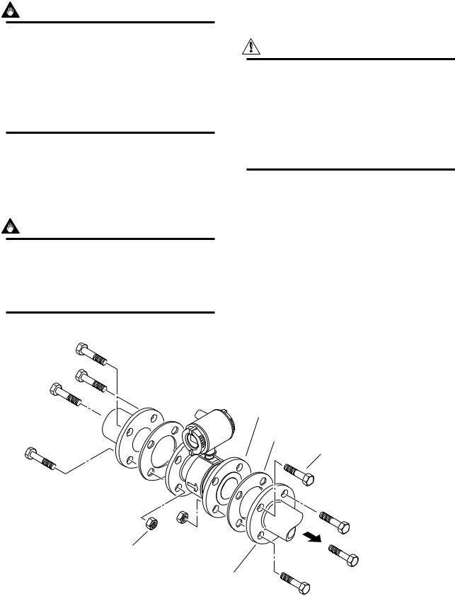
3.3.3Nominal Diameter 15 mm (0.5in) to 200 mm (8in) Flange Type
IMPORTANT
Please use appropriate bolts and nuts according to process connection. Please use compressed non-asbestos fiber gasket, PTFE gasket or the gasket which has equal elasticity. In case of optional code /FRG, please use rubber gasket or others which has equal elasticity. Be sure the inner diameter of the gasket does not protrude to inner piping. (Refer to Table 3.3.6)
(1) Mounting Direction
Please mount the Magnetic Flowmeter matching the flow direction of the fluid to be measured with the direction of the arrow mark on the flowmeter.
IMPORTANT
3. INSTALLATION
(2) Tightening Nuts
Please tighten the bolts according to Torque Values in Table 3.3.7. In case of PVC piping, please select optional code /FRG, use rubber gasket and tighten with the torque value in table 3.3.8.
CAUTION
As the lining material is Fluorocarbon PFA, it is possible that bolts loose by its character as time passes. Please tighten the nuts regularly. Please be sure to tighten the bolts following prescribed torque values. Please tighten the flange bolts diagonally with the same torque values, step by step up to the prescribed torque value.
If it is impossible to match the direction, please never remodel to change direction of the terminal box. In case the measuring fluid flows against the arrow direction, please refer to the section 5.3.6 Reversing Flow Direction.
Please use appropriate bolts and nuts according to process connection.
Flange
(Flow Tube)
Gasket
Bolt
Nut
Flange (Piping side)
F0312.EPS
Figure 3.3.3 Mounting Procedure (Size: 15 mm (0.5in) to 200 mm (8in))
3-8 |
IM 1E10B0-01E |

|
|
|
|
|
|
|
|
|
|
|
|
|
|
|
|
|
|
|
|
|
|
3. INSTALLATION |
|
Table 3.3.7 |
Tightening Torque Values for Metal Piping in N-m{kgf-cm} [in-lbf] |
|
|
|
|
|
|
||||||||||||||||
|
|
|
|
|
|
|
|
|
|
|
|
|
|
|
|
|
|
|
|||||
Size mm |
|
JIS 10K |
|
JIS 20K |
|
ANSI 150 |
|
ANSI 300 |
DIN PN10 |
|
DIN PN16 |
|
DIN PN40 |
JIS F12(75M) |
|
||||||||
(inch) |
|
|
|
|
|
|
|
|
|
|
|
|
|
|
|
|
|
|
|
|
|
|
|
|
|
|
|
|
|
|
|
|
|
|
|
|
|
|
|
|
|
|
|
|
|
|
|
15(0.5) |
|
4.5 |
- |
6.5 |
|
|
4.5 |
- 6.5 |
|
4.5 - 7.0 |
|
4.5 |
- 7.0 |
|
|
|
|
|
|
4.5 - 6.5 |
|
|
|
|
|
{46 |
- |
66} |
|
{46 |
- 66} |
|
{46 - 71} |
|
{46 |
- 71} |
|
|
|
|
|
|
{46 - 66} |
|
|
||
|
|
[40 |
- |
58] |
|
|
[40 |
- 58] |
|
[40 - 62] |
|
[40 |
- 62] |
|
|
|
|
|
|
[40 - 58] |
|
|
|
|
|
|
|
|
|
|
|
|
|
|
|
|
|
|
|
|
|
|
|
|
|
|
|
25(1) |
13.5 |
- |
19.0 |
|
13.5 |
- 19.0 |
|
11.5 - 15.0 |
|
14.0 |
- 19.0 |
|
|
|
|
|
|
11.5 - 14.0 |
|
|
|||
|
{138 |
- |
194} |
|
{138 |
- 194} |
|
{117 - 153} |
|
{143 |
- 194} |
|
|
|
|
|
{117 - 143} |
|
|
||||
|
[119 |
- |
168] |
|
[119 |
- 168] |
|
[102 - 133] |
|
[124 |
- 168] |
|
|
|
|
|
[102 - 124] |
|
|
||||
|
|
|
|
|
|
|
|
|
|
|
|
|
|
|
|
|
|
|
|
|
|
|
|
40(1.5) |
24.0 |
- |
31.0 |
|
24.0 |
- 31.0 |
|
20.0 - 25.0 |
|
28.0 |
- 37.0 |
|
|
|
|
|
|
25.5 - 31.0 |
|
|
|||
|
{245 |
- |
316} |
|
{245 |
- 316} |
|
{204 - 255} |
|
{286 |
- 377} |
|
|
|
|
|
{260 - 316} |
|
|
||||
|
[212 |
- |
274] |
|
[212 |
- 274] |
|
[177 - 221] |
|
[248 |
- 327] |
|
|
|
|
|
[226 - 274] |
|
|
||||
|
|
|
|
|
|
|
|
|
|
|
|
|
|
|
|
|
|
|
|
|
|
|
|
50(2) |
31.0 |
- |
39.5 |
|
15.0 |
- 19.5 |
|
32.0 - 39.5 |
|
15.0 |
- 19.5 |
|
|
|
|
|
|
34.5 - 39.5 |
|
|
|||
|
{316 |
- |
403} |
|
{153 |
- 199} |
|
{326 - 403} |
|
{153 |
- 199} |
|
|
|
|
|
{352 - 403} |
|
|
||||
|
[274 |
- |
350] |
|
[133 |
- 173] |
|
[283 - 350] |
|
[133 |
- 173] |
|
|
|
|
|
[305 - 350] |
|
|
||||
|
|
|
|
|
|
|
|
|
|
|
|
|
|
|
|
|
|
|
|
|
|||
80(3) |
23.5 |
- |
32.5 |
|
28.5 |
- 41.0 |
|
53.5 - 65.5 |
|
28.5 - 39.0 |
|
|
|
23.5 - 32.5 |
|
|
|
51.0 - 65.5 |
|
||||
|
{240 |
- |
332} |
|
{291 |
- 418} |
|
{546 - 668} |
|
{291 - 398} |
|
|
|
{240 - 332} |
|
|
|
{520 - 668} |
|
||||
|
[208 |
- |
288] |
|
[252 |
- 363] |
|
[473 - 580] |
|
[252 - 345] |
|
|
|
[208 - 288] |
|
|
|
[451 - 580] |
|
||||
|
|
|
|
|
|
|
|
|
|
|
|
|
|
|
|
|
|
|
|
|
|
||
100(4) |
32.5 |
- |
42.5 |
|
40.0 |
- 53.5 |
|
34.5 - 42.5 |
|
40.0 |
- 51.0 |
|
|
|
33 - 42.5 |
|
|
|
72.0 - 85.0 |
|
|||
|
{332 |
- |
434} |
|
{408 |
- 546} |
|
{352 - 434} |
|
{408 - 520} |
|
|
|
{337 - 434} |
|
|
|
{734 - 867} |
|
||||
|
[288 |
- |
376] |
|
[354 |
- 473] |
|
[305 - 376] |
|
[354 - 451] |
|
|
|
[292 - 376] |
|
|
|
[637 - 752] |
|
||||
|
|
|
|
|
|
|
|
|
|
|
|
|
|
|
|
|
|
|
|
|
|
||
150(6) |
65.0 |
- |
94.0 |
|
43.0 |
- 68.0 |
|
68.0 - 100.0 |
|
41.0 |
- 60.0 |
|
|
|
65.0 - 94.0 |
|
|
|
68.0 - 100.0 |
|
|||
|
{663 |
- |
959} |
|
{439 |
- 694} |
|
{694 - 1020} |
{418 - 612} |
|
|
|
{663 - 959} |
|
|
|
{694 - 1020} |
|
|||||
|
[575 |
- |
832] |
|
[381 |
- 602] |
|
[602 - 885] |
|
[363 - 531] |
|
|
|
[575 - 832] |
|
|
|
[602 - 885] |
|
||||
|
|
|
|
|
|
|
|
|
|
|
|
|
|
|
|
|
|
|
|
|
|
||
200(8) |
57.0 |
- |
84.0 |
|
61.0 |
- 92.0 |
|
69.0 - 101.0 |
|
65.0 |
- 93.0 |
|
94.0 - 125.0 |
|
58.0 - 84.0 |
|
|
|
69.0 - 101.0 |
|
|||
|
{581 |
- |
857} |
|
{622 |
- 938} |
{704 - 1030} |
{663 - 949} |
|
{959 - 1275} |
|
{592 - 857} |
|
|
|
{704 - 1030} |
|
||||||
|
[504 - 743] |
|
[540 - 814] |
|
[611 - 894] |
|
[575 - 1106] |
|
[832 - 1106] |
|
[513 - 743] |
|
|
|
[611 - 894] |
|
|||||||
|
|
|
|
|
|
|
|
|
|
|
|
|
|
||||||||||
* Please use compressed no-asbestos fiber gasket, PTFE gasket or the gasket which has equal elasticity. |
|
|
T0307.EPS |
||||||||||||||||||||
|
|
|
|
|
|
|
|
|
|
|
|
|
|
|
|
|
|
|
|
|
|
||
Table 3.3.8 |
Tightening Torque Values for PVC Piping in N-m{kgf-cm} [in-lbf] |
|
|
|
|
|
|
||||||||||||||||
|
|
|
|
|
|
|
|
|
|
|
|
||||||||||||
Size mm |
JIS 10K |
|
JIS 20K |
ANSI 150 ANSI 300 |
DIN PN10 |
|
DIN PN16 DIN PN40 |
JIS G3451 |
|
|
|
||||||||||||
(inch) |
|
|
|
|
|
|
|
|
|
|
|
|
|
|
|
|
|
F12(75M) |
|
|
|
||
|
|
|
|
|
|
|
|
|
|
|
|
|
|
|
|
|
|
|
|
|
|||
15(0.5) |
|
1.3 |
|
|
|
|
1.3 |
|
|
|
|
|
|
1.3 |
|
|
|
|
|
|
|||
|
|
{13} |
|
|
|
|
{13} |
|
|
|
|
|
|
{13} |
|
|
|
|
|
|
|||
|
|
[12] |
|
|
|
|
[12] |
|
|
|
|
|
|
[12] |
|
|
|
|
|
|
|||
|
|
|
|
|
|
|
|
|
|
|
|
|
|
|
|
|
|
|
|
|
|||
25(1) |
|
3.5 |
|
|
|
|
2.8 |
|
|
|
|
|
|
2.7 |
|
|
|
|
|
|
|||
|
|
{36} |
|
|
|
|
{29} |
|
|
|
|
|
|
{28} |
|
|
|
|
|
|
|||
|
|
[31] |
|
|
|
|
[25] |
|
|
|
|
|
|
[24] |
|
|
|
|
|
|
|||
|
|
|
|
|
|
|
|
|
|
|
|
|
|
|
|
|
|
|
|
|
|||
40(1.5) |
|
5.7 |
|
|
|
|
4.6 |
|
|
|
|
|
|
5.7 |
|
|
|
|
|
|
|||
|
|
{58} |
|
|
|
|
{47} |
|
|
|
|
|
|
{58} |
|
|
|
|
|
|
|||
|
|
[50] |
|
|
|
|
[41] |
|
|
|
|
|
|
[50] |
|
|
|
|
|
|
|||
|
|
|
|
|
|
|
|
|
|
|
|
|
|
|
|
|
|
|
|
|
|||
50(2) |
|
8.2 |
|
|
|
|
8.2 |
|
|
|
|
|
|
8.2 |
|
|
|
|
|
|
|||
|
|
{84} |
|
|
|
|
{84} |
|
|
|
|
|
|
{84} |
|
|
|
|
|
|
|||
|
|
[73] |
|
|
|
|
[73] |
|
|
|
|
|
|
[73] |
|
|
|
|
|
|
|||
|
|
|
|
|
|
|
|
|
|
|
|
|
|
|
|
|
|
|
|
|
|||
80(3) |
|
6.2 |
|
|
|
|
12.4 |
|
|
|
|
|
6.2 |
|
|
12.3 |
|
|
|
|
|||
|
|
{63} |
|
|
|
|
{127} |
|
|
|
|
{63} |
|
|
{126} |
|
|
|
|
||||
|
|
[55] |
|
|
|
|
[110] |
|
|
|
|
[55] |
|
|
[109] |
|
|
|
|
||||
|
|
|
|
|
|
|
|
|
|
|
|
|
|
|
|
|
|
|
|
|
|
||
100(4) |
|
8 |
|
|
|
|
|
8.1 |
|
|
|
|
|
8 |
|
|
16.1 |
|
|
|
|
||
|
|
{82} |
|
|
|
|
{83} |
|
|
|
|
|
{82} |
|
|
{164} |
|
|
|
|
|||
|
|
[71] |
|
|
|
|
[72] |
|
|
|
|
|
[71] |
|
|
[142] |
|
|
|
|
|||
|
|
|
|
|
|
|
|
|
|
|
|
|
|
|
|
|
|
|
|
|
|||
150(6) |
|
19.6 |
|
|
|
|
18.8 |
|
|
|
|
|
19.6 |
|
|
21.5 |
|
|
|
|
|||
|
|
{200} |
|
|
|
{192} |
|
|
|
|
{200} |
|
|
{219} |
|
|
|
|
|||||
|
|
[173] |
|
|
|
|
[166] |
|
|
|
|
[173] |
|
|
[190] |
|
|
|
|
||||
|
|
|
|
|
|
|
|
|
|
|
|
|
|
|
|
|
|
|
|
||||
200(8) |
|
17.5 |
|
|
|
|
25.1 |
|
|
26.2 |
|
17.5 |
|
|
28.7 |
|
|
|
|
||||
|
|
{179} |
|
|
|
{256} |
|
{267} |
|
{179} |
|
|
{293} |
|
|
|
|
||||||
|
|
[155] |
|
|
|
|
[222] |
|
[232] |
|
[155] |
|
|
[254] |
|
|
|
|
|||||
|
|
|
|
|
|
|
|
||||||||||||||||
* Please select optional code /FRG and use rubber gasket or others which has equal elasticity. |
T0308.EPS |
|
|
||||||||||||||||||||
3-9 |
IM 1E10B0-01E |
3.4 Wiring Precautions
CAUTION
Confirm that all connections are corrected before applying power to the instrument. Improper wiring may damage the flowmeter.
NOTE
The terminal box and display cover is locked by special screw. In case of opening the terminal box cover, please use the Hexagonal Wrench attached.
CAUTION
Be sure to lock the cover with the special screw using the Hexagonal Wrench attached after tightening the terminal box cover.
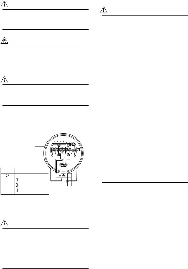
The external signal wirings are connected into the terminal inside the converter. Please connect to each terminal (Please refer to Figure 3.4.1) by taking off a cover backside the converter.
PLS/ALM CUR POWER
L N G
Terminal |
Description |
|
|
|
Symbols |
|
|
||
|
|
|
||
|
Protective grounding |
|
|
|
POWER N– |
Power Supply |
|
|
|
POWER L+ |
|
|
||
|
|
|
||
CUR+ |
Current Output 4 to 20mA DC |
|
|
|
CUR– |
Output |
|
||
|
Power |
|||
PLS/ALM+ |
Pulse, alarm or status output |
|||
Cable |
Cable |
|||
PLS/ALM– |
||||
|
F0313.EPS
Figure 3.4.1 WWiring
3.4.1Protective Grounding
CAUTION
Please be sure to connect protective grounding of ADMAG SE with cable of 2mm2 or larger cross section in order to avoid the electrical shock to the operators and maintenance engineers and prevent the influence of external noise. And further connect the grounding wire to the  mark (100Ω or less).
3. INSTALLATION
3.4.2General Precautions
Please give attention to the followings in wiring.
CAUTION
•Please pay attention to avoid the cable is bended excessively.
•Please do not connect cables outdoors in case of rain to prevent damages from dew formation and to keep insulation inside the terminal box of the flowmeter.
•The all cable ends are to be provided with round crimp-on terminal.
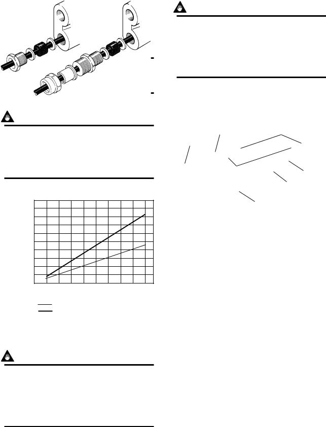
•The power cables and output signal cables must be routed in separate steel conduit tubes or flexible tubes.(except 4-core 24VDC cable wiring.)
•When waterproof glands or union equipped waterproof glands are used, the glands must be properly tightened to keep the box watertight.
•Please install a external switch or circuit breaker as a means of power off (capacitance; 15A, conform to IEC947-1 and IEC947-3). The preferable location is either near the instrument or other places to easy operation. Furthermore, please indicate “power off equipment” on the those external switch or circuit breaker.
•Please be sure to fully tighten the terminal box cover before the power is turned on. After tightening the covers, please be sure to fix it withh the special screw using a hexagonal wrench attached.
•Please be sure to turn off the power before opening the covers.
•In case of DC power supply, a plug is attached. When 4-core cable is used, please put that plug into unused electrical connection port.
3.4.3Power and Output Cables
Power Cable:
•Crimp-on Terminal
•Green/Yellow covered conductors shall be used only for connection to PROTECTIVE CONDUCTOR TERMINALS.
•Conform to IEC277, IEC245 or equivalent national authorization.
Output Cable:
• Please use Polyvinyl chloride insulated and sheathed control cables (JIS C3401) or Polyvinyl chloride insulated and sheathed portable power cables (JIS C3312) or equivalents.
3-10 |
IM 1E10B0-01E |
Outer Diameter:
•6.5 to 12mm in diameter (10.5 to 11.5mm for waterproof gland /ECG, /ECU)
Nominal Cross Section:
•Single wire; 0.5 to 2.5mm2 , Stranded wire; 0.5 to 2.5mm2
3.4.4DC Connections
(1)Connecting Power Supply
IMPORTANT
In case of 24VDC power supply, AC power supplies or reversed polarities cannot be connected. It will cause the fuse to burn out.
3. INSTALLATION
3.4.5Wiring Ports
Please select the most suitable standard of wiring procedure for the wiring ports by customer’s own.
(1)Using the Waterproof Gland
IMPORTANT
To prevent water or condensate from entering the converter housing, waterproof glands are recommended. Do not over-tighten the glands or damage to the cables may result. Tightness of the gland can be checked by confirming that the cable is held firmly in place.
Waterproof gland |
Waterproof gland with union joint |
Optional specification code : /ECG |
Optional specification code : /ECU |
IMPORTANT
In case of 24VDC power supply, the specification for the supply voltage is 24VDC (-15 to +20%), but the input voltage of the converter drops due to cable resistance so it should be used within the following range.
|
1000 |
Supplied Power and Cable Length |
|||
|
(3300) |
|
|
|
|
|
900 |
|
|
|
|
|
(2970) |
|
|
|
|
|
800 |
|
|
|
|
|
(2640) |
|
|
|
|
|
700 |
|
|
|
|
|
(2310) |
|
|
|
|
Allowed |
600 |
|
|
|
|
(1980) |
|
|
|
|
|
cable |
500 |
|
|
|
|
length |
(1650) |
|
|
|
|
m(ft) |
400 |
|
|
|
|
(1320) |
|
|
|
|
|
|
|
|
|
|
|
|
300 |
|
|
|
|
|
(990) |
|
|
|
|
|
200 |
|
|
|
|
|
(660) |
|
|
|
|
|
100 |
|
|
|
|
|
(330) |
|
|
|
|
|
0 |
22 |
24 |
26 |
28 |
|
20 |
||||
|
|
|
Usable range E(V) |
|
|
Cable cross section area : 1.25mm2
Cable cross section area : 2mm2
F0314.EPS
Figure 3.4.2 Supplied Power and Cable Length
(2)Setting Power Supply Frequency
IMPORTANT
In case of DC power supply, the frequency of the power supply has to be adjusted. Please adjust for the local power frequency. The power supply frequency is set in parameter B12 (or Power freq for HART). Refer to 5.2, 6.5.2, or 7.3.4 for data setting procedure.
Gasket |
G 1/2 |
Tightening gland
Washer
Gasket
Tightening gland
G 1/2 |
F0315.EPS |
Figure 3.4.3 Waterproof Gland
(2)Conduit Wiring
In case of conduit wiring, please use the waterproof gland to prevent water flowing through the conduit pipe into the wiring connection.
Please slope the conduit pipe down, and install a drain valve at the low end of the vertical pipe.
Please open the drain valve regularly.
Figure 3.4.4 Conduit Wiring
3-11 |
IM 1E10B0-01E |
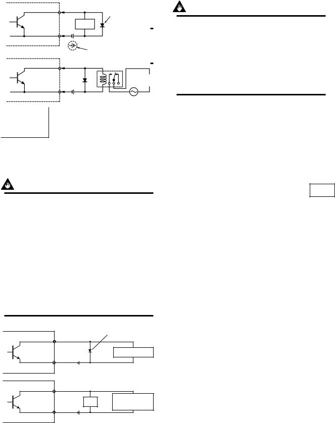
3.4.6Connecting to External Instruments
CAUTION
All the devices to be connected to current output and pulse output must be conformed to CSA1010, CSA950, or IEC950.
(1)Analog Signal Output(4 to 20mADC)
+CUR+
ADMAG SE |
|
|
+ |
Load Resistance |
|
|
|
|
|||
|
RECEIVER |
||||
|
max. 600 |
Ω |
|||
|
|
||||
|
|
|
– |
|
|
|
|
|
|
||
–CUR–
F0317.EPS
Figure 3.4.5 Connection for Analog Signal Output
(2)Pulse Output
IMPORTANT
Please give attention to voltage and polarity in wiring, because it is transister contact(insulation type.
•In case of the filtering constant of Electric Counter is more than the pulse width, it makes signal decreases and can not be calculated correctly.
•In case of input impedance of electric counter is large inductive noise from power supply bring bad influence to measurement. To calculate correctly, it is recommended to use shield cable or to make input impedance small enough within the limits of pulse output of flowmeter.
ADMAG SE |
+ |
PLS/ALM+ |
Protective diode |
|
|
||
PULSE OUT |
|
|
Mechanical counter |
|
– |
PLS/ALM– |
30 V DC, 0.2A. max |
|
|
|
ADMAG SE |
+ |
PLS/ALM+ |
|
|
|
||
PULSE OUT |
|
Load |
Universal counter or |
|
Electronic counter |
||
|
|
|
|
|
– |
PLS/ALM– |
|
|
|
|
F0318.EPS |
Figure 3.4.6 Pulse Output Connection
3. INSTALLATION
(3)Alarm or Status Output
IMPORTANT
This is a transistor contact(insulated type) so attention must be paid to volttage and polarity when making connections.
This output can not switch an AC load. To do this, another relay (see the figure below) is required.
* The alarm output works from “close”(Normal) to “open”(Alarm).
30 V DC, 0.2A. max
F0319.EPS
Figure 3.4.7 Contact Output Connection
3-12 |
IM 1E10B0-01E |
4. BASIC OPERATING PROCEDURES
4.BASIC OPERATING PROCEDURES
All data settings can be performed with the three keys on the front panel (SET,SHIFT, and INC), or using a handheld Brain Terminal (BT) or using a HART communicator. The following sections describe basic data components and how to use the three panel keys. (Please refer to Chapter 6 for the operation via Brain Terminal and Chapter 7 for the operation via HART communicator.)
4.1 Liquid Crystal Display (LCD)
ADMAG SE display panel (if equipped) shows the components as follows.
4:Decimal Point
1:Data Display
M m N k g a l b b l % scftm3 /d /s /h /m
|
SET |
SHIFT |
INC |
3:Unit Display |
|
|
|
|
|
|
2:Infrared Switches (if equipped) |
Figure41. |
ComponentsofDisplay |
|
|
1: Data Display: |
Displays flow rate data, setting data and type of alarm generated. |
||
2: Infrared Switches: |
These keys are used to change the display and type of setting data. |
||
3: Unit Display: |
Displays flow rate units. In order to display other units, the |
||
|
|
required unit label should be selected from the provided data |
|
|
|
sheets. |
|
4: Decimal Point: |
Displays decimal point. |
||
• Structure of the Display
*The Display consists of six figure and five dots for the decimal point between them.
*Two types of data can be entered : direct entry of numerals and entry of desired data items using codes.
Please refer to Chapter 11. Parameter List for information on how to change settings.
The infrared switches operates as “ON” status by detecting the infrared ray reflection from a finger put over the switches through the glass plate of the cover. Switches are just below the printed letters SET, SHIFT, or INC on the faceplate and are circled with a white line.
NOTE When you “touch” the swiches, please note the follwing.
The switches may operate even when you don’t touch the glass plate if your finger comes near just above the glass plate. so please touch the switches sliding in your finger from the lower part of the glass plate. Also be sure not to touch more than one switch at one time by covering your other fingers over the faceplate.
4-1 |
IM 1E10B0-01E |
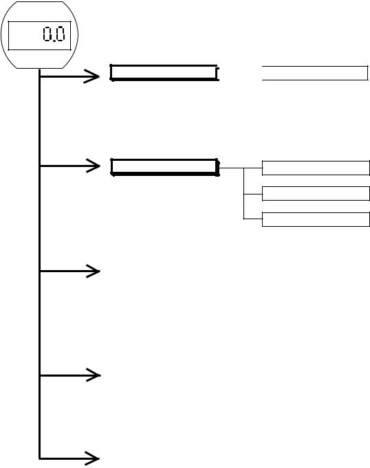
4. BASIC OPERATING PROCEDURES
4.2 Types of Display Data
The Display Data is divided into 5 types as follows.
Please refer to section 4.2.2
Flow Rate Display Mode 

 Pass-Word Input Mode
This mode indicates the instantaneous flow rate and totalization data. Display settings can be set in the Setting Mode and parameter No.“d01” (DISP SELECT) by using infrared switches, Brain Terminal, or HART communicator.
Setting Mode
This mode makes certain about contents of parameter and rewrite data.This mode is called up from Flow Rate Display Mode by touching the SET key for 3 sec. and inputting a password.
Please refer to section 4.2.3
Number Changing Mode
Data Changing Mode
Data Confirmation Mode
|
Alarm Display Mode |
|
Please refer to section 4.2.4 |
|
|
When an alarm occurs in the Flow Rate Display Mode, this mode indicates the alarm code number and normal data alternately.
|
Auto Zero Mode |
|
Please refer to section 4.2.5 |
|
|
||
|
|
|
|
This mode is indicated during automatic zero setting.
|
Indicator Error Mode |
|
Please refer to section 4.2.6 |
|
|
||
|
|
|
|
This mode is shown in case the keys keep staying “ON” by stains or obstacles on front glass of the case.The error is canceled by cleaning them.
4-2 |
IM 1E10B0-01E |
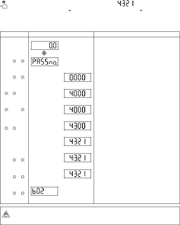
4. BASIC OPERATING PROCEDURES
4.2.1The Initial Procedure to Change the Display Mode
•The procedure of changing the display from the Flow Rate Display Mode into the Setting Mode by using infrared switches on the converter is described as follows.
(1) Procedure in General
|
|
|
|
|
|
|
|
|
|
The Flow Rate |
|
|
|
The Pass-word |
|
|
|
|
The Setting |
|
|
||||||||
Display Mode |
SET key |
Input Mode |
|
Password Input |
Mode |
||||
|
|
|
|
||||||
|
(for 3 sec.) |
(It is always “4321”.) |
|||||||
(2) Procedure in Detail
Switch Operation |
Display |
Description |
|
(After power on) |
(example) |
|
|
SET SHIFT |
INC |
|
To go to the Setting Mode, it is needed to go to the Password |
|
|
|
|
(for 3 sec.) |
|
Input Mode first. Please touch the SET key for 3 sec., and the |
|
|
display goes into the Password Input Mode. |
||
|
|
|
|
SET SHIFT |
INC |
|
By touching the SET key again, the display goes into the |
|
|
|
Number Input Mode. Please input the Password as follows, by |
|
|
|
touching the SHIFT and INC keys. |
SET SHIFT |
INC |
|
By touching the INC key for some moment, change “0” into |
|
|
|
“4”. |
SET SHIFT |
INC |
|
By touching the SHIFT key, the cursor moves to the next digit. |
SET SHIFT |
INC |
|
By touching the INC key for some moment again, change “0” |
|
into “3”. |
||
|
|
|
|
|
|
|
By continuing this for the rest of two digits, please change the |
|
|
|
whole digits into “4321”. |
SET SHIFT |
INC |
|
By touching the SET key, whole Display is blinking. |
|
|
||
SET SHIFT |
INC |
|
And by touching the SET key again, setting the password is |
|
completed. |
||
|
|
|
|
|
|
(Setting is now completed) |
|
|
|
|
By touching the SET key again, the display goes to the number |
SET SHIFT |
INC |
|
changing mode. |
In the Password Input Mode, if keys were not operated for more than 20 sec., or if NOTE correct password were not set, the display goes back into the Flow Rate Display Mode
automatically.
4-3 |
IM 1E10B0-01E |
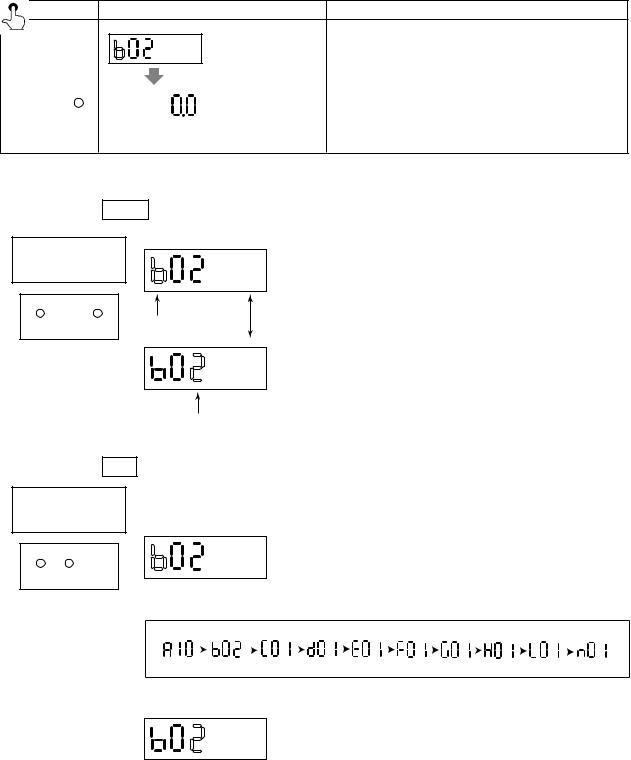
4. BASIC OPERATING PROCEDURES
• The procedure of returning from the Setting Mode to the Flow Rate Display Mode by using infrared switch on the converter is described as follows.
Switch Operation |
Display |
Description |
The number changing mode of the Setting Mode.
SET SHIFT INC |
|
(example) |
After all settings have been completed, touch the SET key |
|
|
||||
|
|
simultaneously while touching the SHIFT key. Then the display |
||
|
|
|
goes back to the Flow Rate Display Mode. |
|
(SHIFT key first) |
||||
|
||||
•Additional information on the functions of the keys is described here.
(1)Functions of SHIFT key
Number
Changing Mode
SET SHIFT INC
When the SHIFT key is touched in the Number Changing Mode, it shows as follows.
<< The Cursor Position moves alternately by touching the
SHIFT key.
Cursor Position
Cursor Position
(2) Functions of INC
Number
Changing Mode
key
The INC key in the Number Changing Mode has each working at each cursor position. a) In case the Cursor Position is at upper figure
SET SHIFT INC
The parameter number changes the followings by touching the INC key.
b) In case the Cursor Position is at lower figure
The parameter number changes from small number to big one by touching the INC key. For example; 02, 03, ..., 37, 02, 03, ... (in case of parameters with “b”)
4-4 |
IM 1E10B0-01E |

4. BASIC OPERATING PROCEDURES
4.2.2Flow Rate Display Mode
•Flow Rate Display Mode indicates flow rates and totalization data. ADMAG SE can indicate 12 types as follows.
|
|
INDICATOR |
|
HART |
||
DISPLAY ITEM |
CONTENTS |
|
|
BT200 SETTING |
||
Parameter |
Code |
|||||
Communicator |
||||||
|
|
No. |
No. |
|
||
|
|
|
|
|||
|
|
|
|
|
|
|
|
Instantaneous flow rate is displayed |
d01 |
00 |
D01: DISP SELECT |
Disp Select |
|
Flow Rate (%) |
within a range of -8 (or –108%) to |
|||||
RATE(%) |
PV % rnge |
|||||
|
108% for the span. |
|
|
|||
|
|
|
|
|
||
|
|
|
|
|
|
|
|
The actual meter rate of instataneous |
|
|
|
|
|
|
flow rate is displayed. (See NOTE) |
|
|
|
|
|
Flow Rate |
The decimal place is the same as for |
d01 |
01 |
D01: DISP SELECT |
Disp Select |
|
Actual Flow Rate |
the span setting. However, since a |
|||||
RATE |
PV |
|||||
|
decimal point set at the least |
|
|
|||
|
|
|
|
|
||
|
significant bit cannot be displayed. |
|
|
|
|
|
|
|
|
|
|
|
|
Actual Flow Rate |
Display actual flow rate totalization |
d01 |
02 |
D01: DISP SELECT |
Disp Select |
|
Totalization Values |
value |
FOR. TOTAL |
Totl |
|||
|
|
|||||
|
|
|
|
|
|
|
Reverse Flow Rate |
Display reverse flow rate totalization |
d01 |
03 |
D01: DISP SELECT |
Disp Select |
|
Totalization Values |
value |
REV. TOTAL |
Rev. totl |
|||
|
|
|||||
|
|
|
|
|
|
|
Differential Between the |
Differential totalization between |
d01 |
04 |
D01: DISP SELECT |
Disp Select |
|
Forward and Reverse Flow |
forward totalization and reverse |
|||||
Diff. totl |
||||||
Totalization Values |
totalization is displayed. |
|
|
DIF. TOTAL |
||
|
|
|
|
|||
|
|
|
|
|
|
|
Alternate Display of Flow Rate |
Display alternately between display |
d01 |
05 |
D01: DISP SELECT |
Disp Select |
|
(%) and Forward Flow Rate |
of “RATE(%)” and “FOR. TTL” |
|||||
RATE %/FOR TTL |
PV % rnge/Totl |
|||||
Totalization Values |
every 4 second interval. |
|
|
|||
|
|
|
|
|||
|
|
|
|
|
|
|
Alternate Display of Actual |
Display alternately between display |
|
|
D01: DISP SELECT |
Disp Select |
|
Flow Rate and Forward Flow |
d01 |
06 |
||||
of “RATE” and “FOR. TTL”. |
RATE/FOR TTL |
PV/Totl |
||||
Rate Totalization Values |
|
|
||||
|
|
|
|
|
||
|
|
|
|
|
|
|
Alternate Display of Actual |
Display alternately between display |
d01 |
07 |
D01: DISP SELECT |
Disp Select |
|
Flow Rate and Forward Flow |
of “RATE” and “RATE(%)” every 4 |
|||||
RATE/RATE % |
PV % rnge/PV |
|||||
Rate(%) |
second interval. |
|
|
|||
|
|
|
|
|||
|
|
|
|
|
|
|
Alternate Display of Flow Rate |
Display alternately between display |
d01 |
08 |
D01: DISP SELECT |
Disp Select |
|
(%) and Reverse Flow |
of “RATE(%)” and “REV. TTL” |
|||||
RATE %/REV. TTL |
PV % rnge/Rev. totl |
|||||
Totalization Values |
every 4 second interval. |
|
|
|||
|
|
|
|
|||
|
|
|
|
|
|
|
Alternate Display of Forward |
Display alternately between display |
|
09 |
D01: DISP SELECT |
Disp Select |
|
Flow Rate and Reverse Flow |
of “RATE” and “REV. TTL” every 4 |
d01 |
||||
RATE/REV. TTL |
PV/Rev. totl |
|||||
Totalization Values |
second interval. |
|
|
|||
|
|
|
|
|||
|
|
|
|
|
|
|
Alternate Display of Flow Rate |
Actual flow rate (%) and differential |
|
|
D01: DISP SELECT |
Disp Select |
|
between forward and reverse |
d01 |
10 |
||||
(%) and Differential Flow |
||||||
Totalization Values |
totalization values are indicated |
|
|
RATE %/DIF. TTL |
PV % rnge/Diff. totl |
|
alternately every 4 sec. |
|
|
|
|
||
|
|
|
|
|
||
|
|
|
|
|
|
|
Alternate Display of Forward |
Actual flow rate and forward and |
d01 |
11 |
D01: DISP SELECT |
Disp Select |
|
Flow Rate and Differential |
reverse totalization values are |
|||||
RATE/DIF. TTL |
PV/Diff. totl |
|||||
Flow Totalization Values |
indicated alternately every 4 sec. |
|
|
|||
|
|
|
|
|||
|
|
|
|
|
|
|
|
• |
The display can set the units by setting parameter No.“b04” and “b05”. |
NOTE |
• |
When special display of flow rate is specified in parameter “d10 flow user unit”, this |
|
|
special display has higher priority in displaying than actual flow rate. |
|
|
|
|
• |
Those 12 types function can be selected and set by changing into the Setting Mode. |
|
|
(Please refer to 4.2.3 Setting Mode.) |
|
• |
Those 12 types function can be selected by using infrared switches, Brain Terminal, |
|
|
or HART communicator. (For using BT, please refer to Chapter 6. OPERATION VIA |
|
|
BRAIN TERMINAL(BT 200). For using HART communicator, Chapter 7. OPERA- |
|
|
TION VIA HART Communicator.) |
4-5 |
IM 1E10B0-01E |
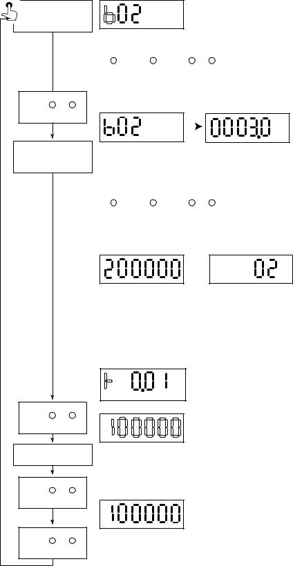
4. BASIC OPERATING PROCEDURES
4.2.3Setting Mode
Number
Changing Mode
The Setting Mode confirms contents of parameter and rewrite data.
•Detailed procedures of data setting are explained in “ Chapter 5. Function and Data Settings”.
•Procedure of data setting
* When the display is in the Setting Mode just after power ON, it always starts from “b02”.
* After that, it starts from the former selected number.
Cursor position is blinking.
|
|
|
* Keys for number changing |
SET SHIFT INC |
|
SET SHIFT INC |
|
|
SHIFT: for changing positions (to the right) |
||
|
|
|
|
|
|
|
INC: for changing alphabets or numerals |
SET SHIFT INC
Data Changing
Mode
*By touching the SET key the display goes to the Data Changing Mode.
*Two types of data can be entered : direct entry of numerals and entry of desired data items using codes. Please refer to “Chapter 11. Parameter List” for information on how to change settings.
SET SHIFT INC |
|
SET SHIFT INC |
* Keys for data changing |
|
|
|
SHIFT: for changing positions (to the right) |
|
|
|
INC: for changing numerals or the position of |
|
|
|
decimal point |
* Data types are as follows.
Direct entry of numerals Entry of selected number
5-figure data = A decimal point is sure to show somewhere, The last figure (6th figure) is always SPACE.
6-figure data(totalized value) = A decimal point doesn't show anywhere and no SPACE. Selection type data = It is always 2-figure(other figures are always SPACE).
The marks are always shown at the highest figure.
It changes: “+” and “–” (“+” is shown as “  ”.)
”.)
SET SHIFT INC
Data Confirmation Whole display is blingking.
Mode
SET SHIFT INC
SET SHIFT INC |
Data is completed. |
|
*When it is the Data Changing Mode and touch SET key, it changes into the Data Confirmation Mode, whole of the display begins to blink.
*During the display is blinking, touch the SET key, then the data is completed.
*Then touch the SET key again and the display goes back to the Number Changing Mode.
*During the display is blinking and touch other keys except the SET key, the data setting is canceled and the display goes back to the Number Changing Mode.
4-6 |
IM 1E10B0-01E |
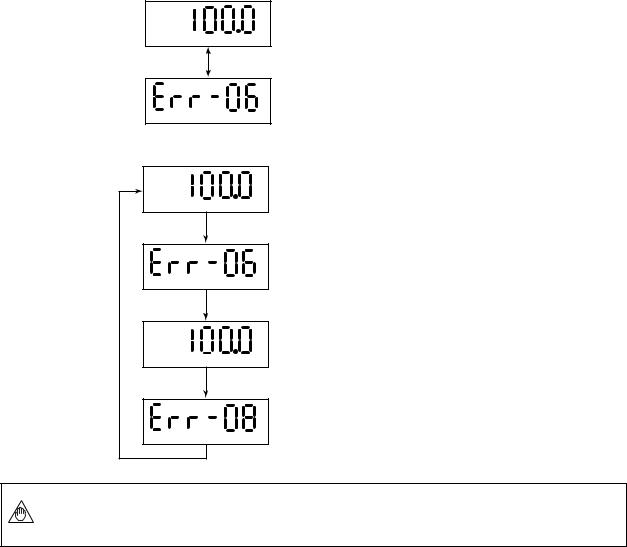
4. BASIC OPERATING PROCEDURES
4.2.4Alarm Display Mode
•When an alarm occurs, a content of the alarm is shown as an alarm code number. However, this mode is available during the Flow Rate Display Mode.
In this mode, alarm number and flow rate are shown alternately.
For example;
• When alarm No. 6 is raised.
<< Flow Rate is indicated for 4 sec.
%
<< Alarm No. is indicated for 2 sec.
• When alarm No.6 and No.8 are raised at the same time.
<< Flow Rate is indicated for 4 sec.
%
<< Alarm No.6 is indicated for 2 sec.
<< Flow Rate is indicated for 4 sec.
%
<< Alarm No.8 is indicated for 2 sec.
NOTE |
For further description of the alarm functions, please refer to “Chapter 8.2 Self- |
diagnostics Functions”. |
4-7 |
IM 1E10B0-01E |
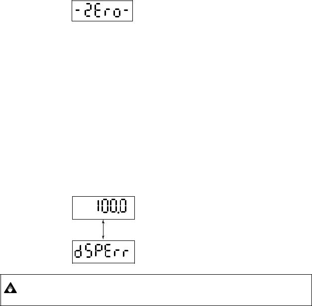
4. BASIC OPERATING PROCEDURES
4.2.5Auto Zero Mode
•Three ways of the auto zero adjustment can be done by using the infrared switches on the converter, BT Terminal, or HART communicator.
Please refer to “8.1 Pre-Operation Zero Adjustment” in detail.
•The display can be changed into the Auto Zero Mode from any mode.
•The Auto Zero Mode is shown as follows (for 20sec.).
•When the Auto Zero Mode is finished, the display goes back into the Flow Rate Display Mode automatically.
4.2.6Indicator Error Mode
In the event the glass is stained or objects are placed near or on the glass, the switches can be activated due to the infrared deflection. This will cause the "Password Input Mode" to be displayed frequently and make the normal display mode unavailable. The following comments relate to this possible occurrence.
*When the front glass of case is stained, please wipe out the glass by soft and dry cloth.
*In case that each key keeps touching for more 120 sec. and it is continued, the Password Input Mode is not available to enter.
*In case all keys are “OFF” for more 3 sec. , this mode is cancelled.
*This condition (the above-mentioned) is not an alarm, but the followings are shown on LCD to indicate this condition.
(4 to 20 mA Output , Status Output , Flow Rate Indication Value and Self-check Function work normally.)
*When these errors are raised, the display indicates alternately as follows.
<< Flow Rate is indicated for 4 sec.
%
<< Warning is indicated for 2 sec.
In case of the front cover is loosened, "dSPErr" may occur, so please make sure the
IMPORTANT |
cover is always fastened tightly. |
|
4-8 |
IM 1E10B0-01E |
5. FUNCTION AND DATA SETTINGS
5.FUNCTION AND DATA SETTINGS
A Magnetic flowmeter calculates volume flow rate from a minute voltage that corresponds to the flow velocity of a fluid an outputs as a 4 to 20mA signal.
The three parameters must be set to obtain a correct signal.
Nominal size, flow span and meter factor must be set.
NOTE |
In these three factors, Nominal size (unit:mm) and meter factor are set before shipment. |
|
|
|
|
|
This chapter explaines how to set flow span, other functions and data settings. |
|
Please set data correctly. |
|
|
|
|
|
|
|
|
|
|
|
|
|
|
|
|
|
• |
you cannot set the leftmost digit of display to numeric value |
|
||
|
|
|
|
|
|
|
greater than "4". If the leftmost digit of the span must be "4| or |
|
||
NOTE |
|
|
|
|
more, set the numeric value beginning from the digit second |
|
||||
|
|
from the left on the display (the fourth digit). |
|
|||||||
|
|
|
|
|
|
• If the leftmost digit of the display is set to "3", the digits to its |
|
|||
|
|
|
|
|
|
|
right can be set to "0" only, regardless of the decimal point |
|
||
|
|
|
|
|
|
|
position |
|
|
|
|
|
|
|
|
|
|
|
|
|
|
|
|
|
|
|
|
|
|
|
|
|
|
Basic Key Operations |
|
|
|
|
|||||
|
|
|
|
|
|
|
Item |
Key Operation |
|
|
|
|
|
|
|
|
|
||||
|
|
How to change the display into the setting mode? |
SET |
|
|
|||||
|
|
|
|
|
|
|
||||
|
|
How to move the cursor on the display during parameter setting? |
SHIFT |
|
|
|||||
|
|
|
|
|
|
|
||||
|
|
How to change the display into the data changing mode? |
SET |
|
|
|||||
|
|
|
|
|
|
|
||||
|
|
How to move the cursor in the data changing mode? |
SHIFT |
|
|
|||||
|
|
|
|
|
|
|
|
|||
|
|
How to change the data? |
|
INC |
|
|
||||
|
|
|
|
|
|
|
|
|||
|
|
Finally, How to input the set data? |
|
SET (Twice) |
|
|
||||
|
|
|
|
|
|
|
|
|
|
|
5.1 Setting Flow Span
(1) Determing the Flow Span
The flow rate span is the instantaneous flow rate value at which the output current is to be 20mA.
Please determine the span under considering the followings.
•Please set the maximum flow rate at the most variable flow rate line.
If the flow rate of the fluid exceeds the flow rate span value, the flow rate that exceeds this value (20mA or more) is not output and the flowmeter will not display the correct flow rate. (108% or more can't be output)
•In a line where the flow rate is comparatively stable, set a value that is 1.5 to 2.0 times larger than the normal flow rate.
•Please set a value that will correspond to a flow velocity of 0.3 to 10m/s. Please comfirm the flow velocity by sizing data or parameter No. “b13”. (Parameter No. “b13” indicates corresponding flow velocity to set span)
•The basic input value for display is flow span value. It is recommended that the accuracy of the first digit is in a 0.05 to 0.1% in case inputting the flow rate span value.
For example, 30m3/h should be set as 30.00m3/h.
•In a span setting, the maximum value that can set is “30000” except any relation with decimal position.
5-1 |
IM 1E10B0-01E |

5. FUNCTION AND DATA SETTINGS
(2) Span Settings by Infrared Switches on the Converter (Example: Flow Span 30.00m3/h)
● Span Value Setting
Switch Operation |
Display |
Description |
|
|
|
(See 4.2.1 The initial |
|
|
|
procedure to change the |
Change into the password input mode through the setting mode. |
|
|
display) |
|
|
|
|
(Please refer to Chapter 4 “BASIC OPERATION |
SET SHIFT |
INC |
|
PROCEDURES.”) |
SET SHIFT |
INC |
|
By touching the SHIFT and INC key, set the parameter |
|
|
|
No. “b03”. |
SET SHIFT |
INC |
|
|
|
|
Defalt is set as 1.0000. Please change this into 0030.0. |
|
SET SHIFT |
INC |
|
By touching the SHIFT key, change into the data changing |
|
|
|
mode. |
SET SHIFT |
INC |
|
By touching the INC key, change into “0”. |
SET SHIFT |
INC |
|
By touching SHIFT key, the cursor moves to the decimal point. |
|
|
|
The decimal point on the cursor can be moved by touching the |
|
|
|
INC key. |
SET SHIFT |
INC |
|
|
SET SHIFT |
INC |
|
And by touching SHIFT key, blinking part moves to the right. |
SET SHIFT |
INC |
|
By touching INC key, change into “3”. |
SET SHIFT |
INC |
|
|
|
|
|
By touching SET key, whole Display is blinking. |
|
|
|
And by touching the SET key again, the data is completed. |
SET SHIFT |
INC |
|
|
|
|
(Setting is now completed) |
|
SET SHIFT |
INC |
|
|
5-2 |
IM 1E10B0-01E |
Loading...