


 Loading...
User’s
Manual
Model SC72
Personal Conductivity Meter
IM 12D03D02-01E
IM 12D03D02-01E
3rd Edition
Preface
Preface
Before using the Model SC72 Personal Conductivity Meter, read this manual thoroughly.
For safe use of this meter, the meter and the instruction manual include the following symbol marks.
 WARNING : Indicates that serious injury may result, if users fail to follow instruction manual procedures.
 CAUTION : Indicates that minor injury to personnel, or serious damage to the product, may result if users fail to follow procedures in the
instruction manual.
 WARNING
Do NOT use this instrument where there is a possibility of electrical shock.
Do NOT touch any part of the electrode immediately after measuring very hot liquids — otherwise, you may get burnt.
 CAUTION
If the meter will not be used for an extended period of time, be sure to remove the battery. Otherwise battery leakage may occur, and may cause damage to the meter or cause erroneous meter operation.
The contents of this manual are subject to change without prior notice.
Yokogawa Electric Corporation assumes no liability for damage, defects, or loss of the product caused by any of the following:
User error;
Inappropriate or out-of-specifications use of the product;
Use in an unsuitable environment;
Repair or modification of this or related products by persons other than Yokogawaauthorized engineers.
IM 12D03D02-01E |
|
3rd Edition: Aug. 2009 (YK) |
|
All Rights Reserved, Copyright © 2004, Yokogawa Electric Corporation |
1 |
Preface
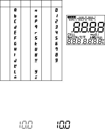
Liquid crystal display (LCD) display characters
The numeric LCD display is used to mimic alphabetic characters, as shown below:
Alphabet Display |
Alphabet |
Display Numerals |
Display |
A |
N |
0 |
|
B |
O |
1 |
|
C |
P |
2 |
|
D |
Q |
3 |
|
E |
R |
4 |
|
F |
S |
5 |
|
G |
T |
6 |
|
H |
U |
7 |
All display elements shown ON |
I |
V |
8 |
|
J |
W |
9 |
|
KX
LY
M |
Z |
F00.EPS
Note Regarding Panels Shown in this Manual:
Panels shown in this manual should be regarded as examples. Actual panel format may vary depending on parameter settings and on type of connected sensor.
Showing all display elements lit
Display (gray represents flashing state)
Flashing state: |
Lit state: |
2 |
IM 12D03D02-01E |
Preface
Warranty and Service
Yokogawa products and parts are guaranteed to be free from defects in workmanship and materials under normal use and service for a period of (typically) 12 months from the date of shipment from the manufacturer.
Individual sales units may offer different warranty periods, so the original purchase order should be consulted for the conditions of sale. Damage caused by normal wear and tear, inadequate maintenance, corrosion, or due to chemical processes, is excluded from this warranty coverage.
In the event of a warranty claim, any items that are considered to be defective should be sent (freight paid) for repair or replacement (at Yokogawa discretion) to the service department of the relevant sales unit. The following information must be included in a letter accompanying the returned items:
Model code and serial number
Copy of original purchase order showing the date
Length of time used, and the measuring environment
Fault symptoms, and circumstances of failure
Statement whether service under warranty or out-of-warranty service is requested
Complete shipping and billing instructions for return of goods, plus the name and phone number of a contact person who can be reached for further information
Goods that have been in contact with process fluids must be decontaminated / disinfected before shipment, and a statement to this effect should be included. Safety data sheets for all process components that the goods have exposed to should also be included.
IM 12D03D02-01E |
3 |
|

Contents
CONTENTS
Preface ...................................................................................................................... |
1-1 |
||
1. |
Outline ................................................................................................................. |
1-1 |
|
|
1.1 |
Features ......................................................................................................................... |
1-1 |
|
1.2 |
Personal Conductivity Meter Specifications .................................................................. |
1-2 |
|
1.3 |
When You Receive This Conductivity Meter ................................................................. |
1-3 |
|
1.4 |
Contents of Model SC72 Personal Conductivity Meter Package ................................. |
1-4 |
|
1.5 |
Component Names and Functions ................................................................................ |
1-5 |
|
1.6 |
Sensor Part Names and Functions ............................................................................... |
1-6 |
|
1.7 |
Options (Available Separately) ...................................................................................... |
1-8 |
|
1.8 |
Spare Parts .................................................................................................................... |
1-8 |
2. |
Preparation .......................................................................................................... |
2-1 |
|
|
2.1 |
Installing the Batteries ................................................................................................... |
2-1 |
|
2.2 |
Connecting Sensor Cable .............................................................................................. |
2-2 |
|
2.3 |
Setting Date and Time ................................................................................................... |
2-3 |
|
2.4 |
Setting Temperature Unit .............................................................................................. |
2-4 |
|
2.5 |
Setting Cell Constant ..................................................................................................... |
2-4 |
|
2.6 |
Setting Temperature Compensation Coefficient ........................................................... |
2-6 |
3. Measurement ...................................................................................................... |
3-1 |
||
|
3.1 |
Precautions .................................................................................................................... |
3-1 |
|
3.2 |
Measurement Procedures ............................................................................................. |
3-2 |
|
3.3 |
Measurement Panel ....................................................................................................... |
3-3 |
|
3.4 |
Saving Measured Value ................................................................................................ |
3-3 |
4. Keyswitch Functions .......................................................................................... |
4-1 |
||
|
4.1 |
Names and Functions of Keys ...................................................................................... |
4-2 |
|
4.2 |
Liquid Crystal Display and Display Items ...................................................................... |
4-4 |
|
4.3 |
Function Modes ............................................................................................................. |
4-5 |
5. Handling of the SC72 Personal Conductivity Meter ........................................ |
5-1 |
||
|
5.1 |
Tips to Maintain Meter Performance ............................................................................. |
5-1 |
|
5.2 |
Washing the Electrode .................................................................................................. |
5-2 |
|
5.3 |
Cleaning and Drying Connector .................................................................................... |
5-3 |
|
5.4 |
Calibration with Standard Solution ................................................................................ |
5-4 |
|
5.5 |
Storage and Maintenance ............................................................................................. |
5-7 |
6. |
Troubleshooting ................................................................................................. |
6-1 |
|
|
6.1 |
Causes of Abnormal Conductivity Display .................................................................... |
6-1 |
|
6.2 |
Error Messages and Corrective Action ......................................................................... |
6-2 |
|
6.3 |
Causes of Abnormal Measured Value .......................................................................... |
6-4 |
|
6.4 |
Other conditions ............................................................................................................. |
6-4 |
7. |
Measuring Principles of this Instrument .......................................................... |
7-1 |
|
|
7.1 |
What Is Conductivity? .................................................................................................... |
7-1 |
|
7.2 |
Principles of Operation .................................................................................................. |
7-2 |
|
7.3 |
Temperature Compensation and Finding Temperature Compensation Coefficient ..... |
7-3 |
|
7.4 |
Wetted Part Materials of Sensors ................................................................................. |
7-4 |
Appendix ..................................................................................................................... |
1 |
||
Revision Record .......................................................................................................... |
i |
||
4 |
IM 12D03D02-01E |

1. Outline
1. Outline
The Model SC72 Personal Conductivity Meter is an accurate, portable, easy-to-use conductivity meter. It includes not only self-diagnostic functions, to help ensure validity of readings, but also data storage functions to allow users to check past data. The meter is of waterproof construction so that it can safely be used outdoors on a rainy day, and can also withstand being accidentally dropped into water.
1.1 Features
Water resistant case
When this meter is used with its dedicated sensor, it meets the requirements of class IP67 “Degree of Protection to be Provided by Enclosures” in IEC 60529.
Wide measurement range, and convenient “Auto Range” function
Sensors are available to cover measurement ranges between 0 to 2.000 mS/cm and 0 to 2 S/cm. Auto-range functions automatically set the optimum measurement range, making measurement easy.
Automatic temperature compensation
Automatic temperature compensation functions are provided for liquid measurement. Conductivity referenced to 258C can be obtained in solutions with temperature coefficients between 0.00 and 9.99%/8C. The temperature coefficients for NaCl solutions are already stored in the meter.
Calendar and time functions
Internal time functions allow “one-touch checking” of measurement date and time.
Data storage function
Up to 300 conductivities and temperature measurements, and their measurement date and time, can be saved. This function allows you to check past measurement data.
Automatic power off function
The meter will power off automatically if not operated during a preset time interval.
The time interval can be set in one-minute increments in the range 1 to 120 minutes to meet your application requirements. This automatic power off function can also be disabled, but it is wise to leave it enabled to conserve the batteries.
Simple alarm clock function
The meter can issue an alarm signal at a specified time. Even when meter power is turned off, the internal clock can issue an alarm signal.
Internal self-diagnostic functions display messages when appropriate.
Bright easy-to view large LCD
Displays liquid conductivity, liquid temperature, temperature coefficient, date and time.
IM 12D03D02-01E |
1-1 |
|
1. Outline
1.2 Personal Conductivity Meter Specifications
Applicable measurement range:
• Sensors for high purity water measurement (cell constant: 0.05 cm-1)
Conductivity: |
0 to 2mS/cm, 0 to 20mS/cm, 0 to 200mS/cm, 0 to 40MV•cm |
Temperature: |
0 to 808C*1 |
• For general-purpose sensors (cell constant: 5 cm-1) |
|
Conductivity: |
0 to 20mS/cm, 0 to 200mS/cm, 0 to 2mS/cm, 0 to 20mS/cm, |
|
0 to 200mS/cm, |
Temperature: |
0 to 808C*1 |
• For chemical-corrosion-resistant sensors (cell constant: 5 cm-1) |
|
Conductivity: |
0 to 20mS/cm, 0 to 200mS/cm, 0 to 2mS/cm, 0 to 20mS/cm, |
|
0 to 200mS/cm |
Temperature: |
0 to 808C*1 |
• Sensors for high-conductivity measurement (cell constant: 50 cm-1) |
|
Conductivity: |
0 to 2mS/cm, 0 to 20mS/cm, 0 to 200mS/cm, 0 to 2S/cm |
Temperature: |
0 to 808C*1 |
Resolution: Conductivity: Least significant digit: 1 digit;
Temperature: 0.18C
Repeatability (Conductivity):
62% (65% for general-purpose sensor on 0 to 200mS/cm measurement range)
Accuracy (Temperature): 60.78C (in the range 0 to 708C)
618C (when exceeding 708C)
Temperature compensation range:
variable 0.00 to 9.99%/8C, also (preset) NaCl solution temperature coefficient Measurement converted to conductivity at standard temperature of 258C
Measured liquid temperature: 0 to 808C (0 to 508C when the sensor cable is immersed in
|
water) |
Ambient temperature:0 to 508C |
|
Construction: |
IEC 60529, IP67 class of protection from environment |
Power requirement: Two of size AA batteries (LR6)
Automatic power off interval: May be set in range 1 to 120 minutes
Battery life: |
About 200 hours of continuous use, for long-life alkaline battery (life |
|
may vary depending on battery type and ambient conditions) |
External dimensions: Approximately 150 (H) x 61 (W) x 42 (D) mm (not including
|
protruding portions) |
Weight: |
Approximately 220 g (including batteries) |
*1: Display range is from -10 to 1208C.
1-2 |
IM 12D03D02-01E |
|
|
|
1. Outline |
EMC Compliance: |
|
|
|
EMI (Emission): EN 61326-1 Class B |
|
|
|
|
|
|
|
|
Test Item |
Frequency Range |
Basic Standard |
|
Electromagnetic radiation disturbance |
30 to 1000 MHz |
CISPR 16-1 and 16-2 |
|
|
|
|
T0101.EPS
EMS (Immunity): EN 61326-1 Table 2 (For industrial locations)
No. |
Test Item |
Test Specification |
Basic Standard |
Performance |
|
Criteria* |
|||||
|
|
|
|
||
1 |
Electrostatic |
4 kV (contact) |
IEC 61000-4-2 |
A |
|
discharge |
8 kV (air) |
||||
|
|
|
|||
|
|
|
|
|
|
|
|
80 to 1000 MHz, |
|
|
|
|
|
10 V/m (unmodulated) |
|
B** |
|
|
|
80% AM (1 kHz) |
|
|
|
|
RF amplitude |
|
|
|
|
2 |
1.4 to 2.0 GHz, |
|
|
||
modulated |
10 V/m (unmodulated) |
IEC 61000-4-3 |
A |
||
|
electromagnetic field |
80% AM (1 kHz) |
|
|
|
|
|
|
|
|
|
|
|
2.0 to 4.0 GHz, |
|
|
|
|
|
3 V/m (unmodulated) |
|
A |
|
|
|
80% AM (1 kHz) |
|
|
|
|
|
|
|
|
*A: Normal performance within the specification limits: ±20% of the measured value. B: Temporary degration or less of function or performance which is self-recoverable.
** Display value may be affected by strong electromagnetic field. |
T0102.EPS |
1.3 When You Receive This Conductivity Meter
Confirm that all SC72 meter package components (refer to Contents of Model SC72 Personal Conductivity Meter Package in Section 1.4 and sensor models described in Sec. 1.6, “Sensor Part Names and Functions.”) have been received. Carefully inspect the meter and sensor, referring to Section 1.5, “Component Names and Functions” when assembling meter and sensor.
Particular attention should be taken:
*Not to twist or force the cable.
*Not to hit or drop the meter.
*Not to get the sensor connector dirty.
IM 12D03D02-01E |
1-3 |
|

1. Outline
1.4 Contents of Model SC72 Personal Conductivity Meter
Package
|
3 |
Quick Manual |
User©s |
Instrument Card |
|
|
|
|
Manual |
|
|
|
|
6 |
1 |
|
5 |
|
|
|
|
2 |
4 |
|
|
SC72 -


 -
- 
 - AA
- AA
7 |
8 |
9 |
|
|
|
|
|
|
|
|
10 |
11 |
11 |
11 |
11 |
SC72 - 11 - - AA *1 |
SC72 - 21 - |
- AA *1 SC72 - 31 - - AA *1 |
SC72 - 41 - - AA *1 |
|
SC72 - 23 - |
- AA |
|
Model |
|
Suffix code |
Specification |
||
SC72 |
|
|
|
|
Personal conductivity meter |
Sensors |
|
-00 |
|
|
Meter only, without sensor |
|
|
-11 |
|
|
With sensor for high purity water measurement |
|
|
|
|
|
(cable length: 0.75m) |
|
|
-21 |
|
|
With general-purpose sensor |
|
|
|
|
|
(cable length: 0.75m) |
|
|
-23 |
|
|
With general-purpose sensor (cable length: 3m) |
|
|
-31 |
|
|
With chemical-resistant sensor |
|
|
|
|
|
(cable length: 0.75m) |
|
|
-41 |
|
|
With sensor for high-conductiivity measurement |
|
|
|
|
|
(cable length: 0.75m) |
Label |
|
-J |
Japanese |
||
language |
|
-E |
English |
||
- |
|
|
|
-AA |
Always -AA |
No. |
Name |
1 |
Personal conductivity meter |
2 |
Two dry batteries |
3 |
Two instruction manual |
4 |
Non-slip pads (two) |
5 |
Hand strap |
6 |
Instrument card |
7 |
Sensor for high purity water |
|
measurement |
8 |
General-purpose sensor |
9 |
Chemical-resistant sensor |
10 |
Sensor for high-conductivity |
|
measurement |
11 |
Sensor cleaner |
|
(five cotton swabs) |
*1 The meter model number and cell constants, as well as the sensor model no. (SC72SN-u-AA), are |
|
shown on the nameplate. |
F010401.EPS |
1-4 |
IM 12D03D02-01E |
1. Outline
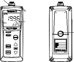
1.5 Component Names and Functions
O-ring
 Sensor cable connector
Used to connect a dedicated conductivity sensor to the personal conductivity meter.
Can attach hand strap here
Display
Displays conductivity, temperature, and temperature coefficient simultaneously.
 Key switches
PERSONAL SC METER
MODEL SC72
STYLE S1.0
No. E000001
2004.
Battery box cover fixing screw
 Instrument name plate with model number and serial number
F010501.EPS
IM 12D03D02-01E |
1-5 |
|
1. Outline
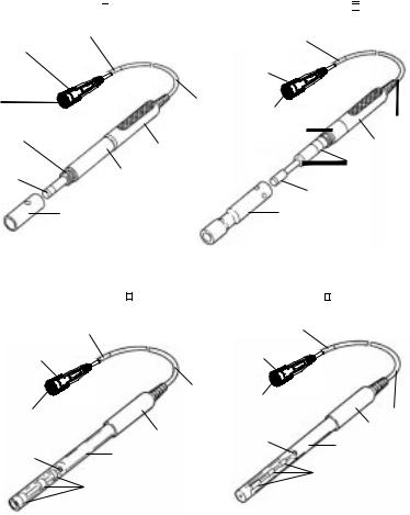
1.6 Sensor Part Names and Functions
Four types of sensors are available for use with the Model SC72 Personal Conductivity Meter:
(1)sensor for high purity water measurement (cell constant 0.05 cm-1),
(2)general-purpose sensor (cell constant 5 cm-1),
(3)chemical-resistant sensor (cell constant 50 cm-1), and
(4)sensor for high-conductivity measurement (cell constant 50 cm-1). Check the model number and cell constant on the name plate to confirm which type of sensor you have.
Model number and cell constants display plate |
example |
|
Cell constants |
||||
MODEL |
SC72SN |
CELL |
|
|
|
|
|
CONST |
|
|
|
||||
|
|
|
|
|
|
||
SUFFIX |
-11-AA |
NO. |
000001 |
STYLE |
S1.0 |
|
|
|
|
|
Made in Japan |
|
|
||
SC72SN Conductivity sensors for personal conductivity meter |
|
|
|||||
Model Suffix code |
Specification |
|
|
|
|
Remarks*1 |
|
SC72SN |
Conductivity sensor for personal conductivity meter |
|
|||||
-11 |
For SC72; for high purity water measurement (cable |
|
|||||
|
length: 0.75m) |
|
|
|
|
|
|
-19 |
For SC82; for high purity water measurement (cable |
K9221XB |
|||||
|
length: 0.75m) *2 |
|
|
|
|
|
|
-21 |
For SC72; for general purpose type (cable length: 0.75m) |
|
|||||
-23 |
For SC72; for general purpose type (cable length: 3m) |
|
|||||
-29 |
|
|
|
|
|
*2 |
K9221XA |
For SC82; for general purpose type (cable length: 0.75m) |
|||||||
-31 |
For SC72; for chemical-resistant type (cable length: |
|
|||||
|
0.75m) |
|
|
|
|
|
|
-39 |
For SC82; for chemical-resistant type (cable length: |
K9221XC |
|||||
|
0.75m) *2 |
|
|
|
|
|
|
-41 |
For SC72; for high conductivity measurement (cable |
|
|||||
|
length: 0.75m) |
|
|
|
|
|
|
-49 |
For SC82; for high conductivity measurement (cable |
K9221XD |
|||||
|
length: 0.75m) *2 |
|
|
|
|
|
|
-AA |
Always -AA |
|
|
|
|
|
|
*1: Part number of SC82 (previous model).
*2: Waterproofing is not guaranteed if you use SC82-type conductivity sensor in conjunction
with SC72 meter. |
F010601.EPS |
1-6 |
IM 12D03D02-01E |
1. Outline
Sensor for high purity water measurement |
General-purpose sensor |
SC72 - 11 - 
 - AA *1
Model number and cell constants display plate
(SC72SN-11-AA) *1
Watertight cover
Prevents moisture from entering connector and causing leakage between pins.
Connector |
Sensor |
|
Connects sensor cable to |
cable |
|
conductivity meter |
|
|
Outer electrode |
|
|
connection |
Sensor grip |
|
(SUS316 |
||
|
||
stainless seel) |
|
|
Inner electrode |
Sensor body |
|
Plastic body can |
||
(SUS316 |
||
stainless seel) |
withstand temperatures |
|
up to 808C. |
||
|
||
|
Outer electrode |
|
|
(SUS316 stainless seel) |
SC72 - 21 - 
 - AA *1
SC72 - 23 - 
 - AA
- AA
Model number and cell constants display plate
(SC72SN-21-AA,*1
SC72SN-23-AA)
Watertight
cover
Connector
Sensor cable
Sensor body
Sensor grip
Inner electrode (Titanium)
Edge electrode (Titanium)
Cover (Plastic)
F010602.EPS
|
Chemical-resistant sensor |
Sensor for high-conductivity measurement |
|
|
SC72 - 31 - - AA *1 |
SC72 - 41 - - AA |
*1 |
Model number and |
Model number and |
|
|
cell constants display plate |
cell constants display plate |
|
|
(SC72SN-31-AA) *1 |
(SC72SN-41-AA) *1 |
|
|
|
|
||
Watertight |
|
Watertight |
|
|
cover |
|
|
cover |
|
|
|
|
|
|
|
|
Sensor |
|
|
|
cable |
Connector |
|
Connector |
|
|
Sensor cable |
|
Sensor grip |
Air vent |
Sensor grip |
|
|
||
|
Sensor body (glass) |
Sensor body (glass) |
|
Air vent |
|
|
|
|
|
|
|
|
|
Inner electrode |
|
|
Inner electrode |
(platinum black) |
|
|
|
|
|
|
(platinum black) |
|
|
*1 SC72SN-u will be described on sensor©s name plateorf the model number. |
F010603.EPS |
||
IM 12D03D02-01E |
1-7 |
|
1. Outline
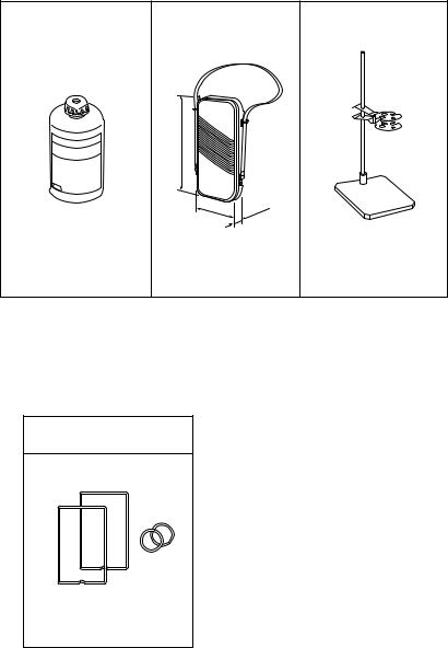
1.7 Options (Available Separately)
The following options are available for the Personal Conductivity Meter for your convenience. When ordering, specify part number shown below.
Standard solution |
Soft case |
Sensor stand |
(Part no.: K9221ZA) |
(Part no.: B9269KJ) |
(Part no.: K9220XN) |
|
|
|
|
Unit: mm |
|
Approx. 280
Appro |
x. 1 |
40 |
|
||
|
|
|
0 |
|
3 |
. |
|
x |
|
ppro |
|
A |
|
0.1mol/l NaCl solution for |
This soft black carrying case holds |
calibration (250ml) |
conductivity meter and sensor. |
This stand holds the sensor when the conductivity meter is used on a table. It is made of rustproof stailess steel.
F010701.EPS
1.8 Spare Parts
O-rings and gaskets are important parts to ensure that the SC72 meter is water resistant. Replace these parts as required. Refer to Section 5.5, “Storage and Maintenance” for replacement.
O-ring and gasket set (Part no.: K9654AY)
Two battery box gaskets
Two sensor connection O-rings
F010801.EPS
1-8 |
IM 12D03D02-01E |
2. Preparation
2. Preparation
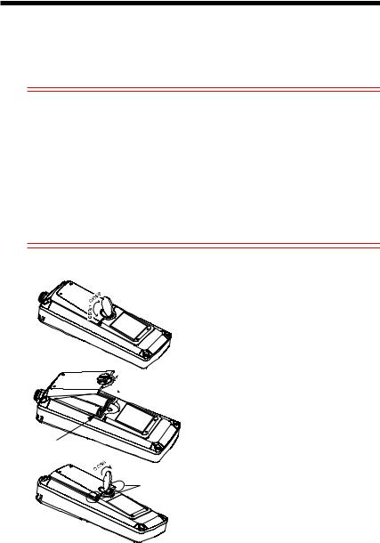
2.1 Installing the Batteries
Install the batteries first.
 CAUTION
Select a relatively moisture-free location when installing batteries in the meter.
When installing batteries, observe correct polarity (battery orientation). Failure to do so may damage to the meter.
Remove batteries from the meter if it is to be stored for an extended period of time.
Do not leave dead batteries in the meter. They may leak and cause meter failure or erratic operation of the meter.
When replacing batteries, replace both batteries at the same time. If only one battery is replaced, the new battery may discharge into the old battery, which may leak chemicals and damage the meter.
If the battery box gasket is damaged or dirty then the unit may no longer be waterproof; replace the gasket in this case.
 458 or more
 Batteries
Gasket
Press with your fingers
(1)Loosen the screw holding the battery box cover using a coin or similar object.
(2)Remove the battery box cover, and then install the batteries observing polarity diagram inside.
(3)Make sure the gasket on the inside rim of the battery box is free of foreign material.
(4)Put the cover back on. Insert the tabs on the top of the cover into the slots at an angle of at least 458 and lower the cover into position.
(5)Press the both ends of the cover down with your fingers and tighten the screw to fix the cover onto the unit using a coin or similar object.
Note: Do not attempt to tighten further when you feel resistance before the cover is fastened in place. Loosen the screw once and retighten.
F020101.eps
IM 12D03D02-01E |
2-1 |
|
2. Preparation
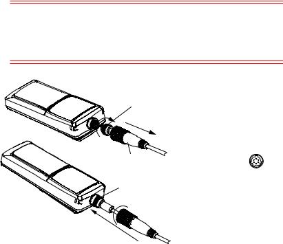
2.2 Connecting Sensor Cable
Connect the sensor cable as shown below.
 CAUTION
Select a relatively moisture-free location when connecting the sensor cable.
When connecting the sensor cable, tighten by turning only the silver locknut, do not turn the cable or waterproof cover. Also take care not wet or contaminate the connector.
Model SC82 sensors can be connected, but these are not guaranteed to be waterproof when used with this meter.
Locknut
(2)(Silver)
(1)
(1)Pull the waterproof cover along the sensor cable away from the connector to expose the locknut.
(2)Connect the connector to the meter body*. Then tighten firmly by turning only the locknut.
*Align the slots of the sensor cable connector with the posts of the
Waterproof cover |
connector on the meter. |
O-ring
 (4)
(4)
(3)
(3)Move the waterproof cover toward the connector until it contacts with the O-ring* on the meter body.
*Make sure that the O-ring is free of foreign material.
(4)Push and rotate the waterproof cover 1/4 turn (90 degrees) clockwise to lock into place.
F020201.eps
Caution:It is recommended that, as far as possible, you leave the sensor connected to the meter to help ensure that the connector does not get dirty.
2-2 |
IM 12D03D02-01E |
2. Preparation
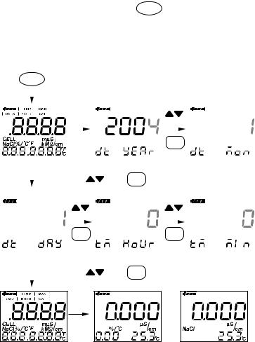
2.3 Setting Date and Time
After installing the batteries, set the date and time. Note that if the power is turned off before setting “minutes,” start with the date setting when you turn on the power next time.
If you replace the batteries, the date is not affected, but the time is reset. Reenter the time.
Caution:If the sensor is not connected then an error will be displayed on the meter.
• Setting method
After installing batteries, press and hold the POWER key for at least one second. Then
all display elements turn on and the date setting display automatically appears. Set year, month, day, hours, and minutes as follows:
Caution:If you stop part way through the date and time setting then the meter will beep and the date and time will not be updated.
After |
POWER |
key for at least 1 sec. |
|
|
|
|
|
|
|
|
||||||
pressing |
|
|
|
|
|
|
|
|
||||||||
|
|
|
|
|
|
|
|
|
|
|
|
|
|
|||
|
|
|
|
|
|
|
|
Year setting |
|
|
to set |
Month setting |
||||
|
|
|
|
|
|
|
|
|
|
|||||||
|
|
|
|
|
|
|
|
|
|
|
|
|
|
|||
|
|
|
|
|
|
|
|
|
|
|
|
|
|
|||
|
|
|
|
|
|
|
|
|
|
|
|
|
|
|
|
|
|
|
|
|
|
After |
|
|
|
|
F/ENT |
|
|
||||
|
|
|
|
|
several |
|
|
|
|
|
|
|||||
|
|
|
|
|
seconds |
|
|
|
|
to confirm |
|
|
||||
|
|
|
|
|
|
|
|
|
|
|
|
|
|
|||
|
|
|
|
|
|
|
|
|
|
|
|
|
||||
|
|
|
|
|
|
|
|
|
|
|
|
|
||||
|
|
|
|
|
|
|
|
to set |
F/ENT |
to confirm |
Minute setting |
|||||
|
|
|
|
|
|
|
|
|||||||||
|
Day setting |
|
|
|
|
Hour setting (24-hour format) |
||||||||||
|
|
|
|
|
|
|
|
|
|
|
|
|
|
|
|
|
|
|
|
|
|
to set |
|
|
|
|
to set |
|
|
||||
|
|
|
|
|
|
|
|
|
|
|
|
|
|
|
||
|
|
|
|
|
F/ENT |
|
|
|
|
F/ENT |
|
|
||||
|
|
|
|
|
to confirm |
|
|
|
|
to confirm |
|
|
||||
|
|
|
|
|
|
|
|
|
|
|
|
|
||||
|
|
|
|
|
|
|
|
|
|
|
|
|
||||
|
|
|
|
|
|
|
|
to set |
F/ENT |
to confirm |
|
|
||||
|
|
|
|
|
|
|
|
|
|
|
|
|
|
|
|
|
After |
or |
|
|
several |
|
seconds |
|
F020301.EPS
IM 12D03D02-01E |
2-3 |
|

2. Preparation
2.4 Setting Temperature Unit
Default temperature units are 8C. To change to 8F, refer to Sec. 4.3 (13) Set temperature units (tP.U) panel.
2.5 Setting Cell Constant
Even for sensors of the same type, each sensor has its own distinct cell constant. So, set the proper cell constant as indicated on the sensor cable.
Whenever sensors are replaced, be sure to change the cell constant setting in the meter accordingly. Cell constants once set are stored in non-volatile memory and are not lost even when the batteries are replaced.
•Setting cell constants
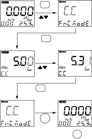
Press the F/ENT key to switch to function mode. Then select the C.C display with the
 key and access the cell constant setting display with the F/ENT key. Use the
 key to set the cell constant, then press the F/ENT key to confirm it.
Refer to Sec. 4.3 (4).
2-4 |
IM 12D03D02-01E |
2. Preparation
F/ENT
for Function mode
select C.C
F/ENT for C.C panel
to enter C.C
F/ENT
MEAS
F020501.EPS |
You can abort this procedure at any time by pressing MEAS to revert to measurement
mode.
IM 12D03D02-01E |
2-5 |
|
2. Preparation
2.6 Setting Temperature Compensation Coefficient
As described in Section 7.3, liquid conductivity varies with liquid temperature. Therefore, if concentration is measured by conductivity, the conductivity must be converted to equivalent conductivity at a certain temperature. This instrument incorporates standard temperature conversion functions to convert liquid conductivity measurements to equivalent conductivity at 258C. To display equivalent liquid conductivity at 258C, set the temperature compensation coefficient as described in this section.
Temperature coefficient for NaCl solutions is stored in this instrument. If any other solution is used, set the temperature compensation coefficient manually.
Refer to Sec. 4.3 (2) Temperature compensation setting (t.Co) panel.
2-6 |
IM 12D03D02-01E |
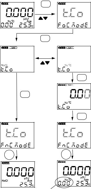
• Set the temperature compensation coefficient
F/ENT
for Function mode
select t.Co
F/ENT for t.Co panel
For NaCl solutions |
Manual setting |
select NaCl or %/8C (%/8F)
F/ENT
F/ENT
F/ENT
2. Preparation
Set the temperature compensation coefficient with the  keys.
keys.
MEAS
MEAS |
The temperature coefficient you set is displayed here |
F020601.EPS |
IM 12D03D02-01E |
2-7 |
|
Loading...