


 Loading...
User’s |
|
Manual |
GCMT Gas Chromatograph |
|
Maintenance Terminal |
|
Software Package |
|
Operation Guide |
IM 11B03G03-03E
IM 11B03G03-03E
4th Edition

i
Introduction
Thank you for purchasing the GCMT Gas Chromatograph Maintenance Terminal Software Package.
The GCMT Gas Chromatograph Maintenance Terminal Software Package (hereafter, it is abbreviated as Maintenance Terminal) is used to monitor and maintain the GC1000 Mark II analyzer on a personal computer by linking the computer to the analyzer through a communication line.
This guide describes the basic procedures for operating the Maintenance Terminal.
• Package Contents
Confirm that the purchased package contains the following:
•GCMT inatallation disks
•GCMT Gas Chromatograph Maintenance Terminal Software Package Operation Guide (IM 11B03G03-03E)
•“GCMT Capture It” software package manual (IM 11B3G1-02E)
• How to User This Guide
This guide first describes how to install the Maintenance Terminal. Start at Chapter 1 after completing installation. The contents of each chapter are as follows:
•Chapter 1..............an overview of the Maintenance Terminal and its basic operations
•Chapter 2..............how to operate the LCD emulator
•Chapter 3 to 6.......how to start the Maintenance Terminal and work with its respective panels
•Appendices..........a functional ovweview of the Maintenance Terminal and list of its messages. Refer to the appendices for details on the menus and messages.
• Intended Readers
The description on installation assumes that reders have a basic knowledge of both the hardware and software required for installing the Maintenance Terminal. This is also true for Chapter 1 and subsequent chapters, as well as for the Windows™ operating system.
However, the basic operations of Windows™ are specifically described in Chapter 1 so you can work with it without prior knowledge. For the detailed operation of Windows, refer to the separate appropriate manual.
• Priority
Precautions in operating and handling the Maintenance Terminal are also found in the online help window of the Maintenance Terminal and the README.TXT file that is registered during installation, inaddition to this guide. The order of precedence among these information sources is:
(1)README.TXT
(2)Help (online manual)
(3)Operation guide (this document)
Media No. IM 11B03G03-03E |
4th Edition : Mar. 2012 (YK) |
IM 11B03G03-03E 4th Edition : Mar. 21, 2012-00 |
All Rights Reserved Copyright © 2006, Yokogawa Electric Corporation |
|
|

ii
Safety Precautions
•In order to protect the system controlled by the product and the product itself and ensure safe operation, observe the safety precautions described in this user’s manual. We assume no liability for safety if users fail to observe these instructions when operating the product.
•Modification of the product is strictly prohibited.
nNotes on Handling User’s Manuals
•Please hand over the user’s manuals to your end users so that they can keep the user’s manuals on hand for convenient reference.
•Please read the information thoroughly before using the product.
•The purpose of these user’s manuals is not to warrant that the product is well suited to any particular purpose but rather to describe the functional details of the product.
•No part of the user’s manuals may be transferred or reproduced without prior written consent from YOKOGAWA.
•YOKOGAWAreserves the right to make improvements in the user’s manuals and product at any time, without notice or obligation.
•If you have any questions, or you find mistakes or omissions in the user’s manuals, please contact our sales representative or your local distributor.
nWarning and Disclaimer
The product is provided on an “as is” basis. YOKOGAWAshall have neither liability nor responsibility to any person or entity with respect to any direct or indirect loss or damage arising from using the product or any defect of the product that YOKOGAWAcan not predict in advance.
nNotes on Software
•YOKOGAWAmakes no warranties, either expressed or implied, with respect to the software’s merchantability or suitability for any particular purpose, except as specified in the terms of warranty.
•This product may be used on a machine only. If you need to use the product on another machine, you must purchase another product.
•It is strictly prohibited to reproduce the product except for the purpose of backup.
•Store the CD-ROM (the original medium) in a safe place.
•It is strictly prohibited to perform any reverse-maintenance operation, such as reverse compilation or reverse assembling on the product.
•No part of the product may be transferred, converted or sublet for use by any third party, without prior written consent from YOKOGAWA.
IM 11B03G03-03E 4th Edition : Mar. 21, 2012-00
iii
Documentation Conventions
n Symbol Marks
Throughout this user’s manual, you will find several different types of symbols are used to identify different sections of text. This section describes these icons.
NOTE
Identifies important information required to understand operations or functions.
TIP
Identifies additional information.
SEE ALSO
Identifies a source to be referred to.
HELP !
Indicates text describing the action to be taken when a message or indication is displayed during an operation.
n Keyboard Inscriptions
Keyboard operations are indicated in this manual as shown in the following example. (Inscription example)
[Shift] + [F1] (Meaning)
Indicates that the operator must press the [F1] key while pressing the [Shift] key.
n Menu Inscriptions
Menu operations are indicated in this manual as shown in the following example. (Inscription example)
Click on [Connect] in the [System] menu. (Meaning)
Click on the [System] menu, then click on the [Connect] command.
n Drawing Conventions
Some drawings may be partially emphasized, simplified, or omitted, for the convenience of description.
Some screen images depicted in the user’s manual may have different display positions or character types (e.g., the upper / lower case). Also note that some of the images contained in this user’s manual are display examples.
IM 11B03G03-03E 4th Edition : Mar. 21, 2012-00

iv
Copyright and Trademark Notices
n All Rights Reserved
The copyrights of the programs and on-line manual contained in the CD-ROM are reserved.
The on-line manual is protected by the PDF security from modification, however, it can be output via a printer. Printing out the on-line manual is only allowed for the purpose of using the product. When using the printed information of the on-line manual, check if the version is the most recent one by referring to the CD-ROM’s version.
No part of the on-line manual may be transferred, sold, distributed (including delivery via a commercial PC network or the like), or registered or recorded on video tapes.
nTrademark Acknowledgments
•IBM is a registered trademark of International Business Machines Corporation.
•Microsoft and Windows are either registered trademarks or trademarks of Microsoft Corporation in the United States and/or other countries.
•Ethernet is a registered trademark of XEROX Corporation.
•All other company and product names mentioned in this user’s manual are trademarks or registered trademarks of their respective companies.
•We do not use TM or ® mark to indicate those trademarks or registered trademarks in this user’s manual.
IM 11B03G03-03E 4th Edition : Mar. 21, 2012-00

Toc-1
GCMT
Gas Chromatograph Maintenance Terminal Software Package
Operation Guide
|
|
IM 11B03G03-03E 4th Edition |
|
CONTENTS |
|
||
Introduction............................................................................................................... |
|
i |
|
Safety Precautions.................................................................................................. |
ii |
||
Documentation Conventions................................................................................ |
iii |
||
Copyright and Trademark Notices........................................................................ |
iv |
||
Installing the Maintenance Terminal...................................................................... |
1 |
||
1. |
Overview of Maintenance Terminal.......................................................... |
1-1 |
|
|
1.1 |
How the Maintenance Terminal Works............................................................ |
1-1 |
|
1.2 |
Maintenance Terminal Group in Program Manager....................................... |
1-2 |
|
1.3 |
Notes Before Use............................................................................................... |
1-4 |
2. |
LCD Emulator Window............................................................................... |
2-1 |
|
|
2.1 |
Starting and Exiting the LCD Emulator........................................................... |
2-1 |
|
2.2 |
Basic Operations............................................................................................... |
2-3 |
3. |
Analyzer Operation Window...................................................................... |
3-1 |
|
|
3.1 |
Starting and Exiting the Maintenance Terminal............................................. |
3-2 |
|
3.2 |
Layout of Analyzer Operation Window........................................................... |
3-5 |
|
3.3 |
Viewing the States of the Detector and Temperature Controller................. |
3-9 |
|
3.4 |
Changing the User Level................................................................................ |
3-11 |
|
3.5 |
Changing the Status/Operation Mode/Measurement Status...................... |
3-12 |
|
3.6 |
Changing the states of the Valves/Detectors/Temperature Controller...... |
3-15 |
|
3.7 |
Changing the Range........................................................................................ |
3-17 |
|
3.8 |
Changing the Valves and Peak Information................................................. |
3-19 |
|
3.9 |
Uploading and Downloading the Parameter Settings................................. |
3-20 |
|
3.10 |
Actions When Alarms Occur.......................................................................... |
3-22 |
4. |
Chromatogram Window............................................................................. |
4-1 |
|
|
4.1 |
Opening and Closing the Chromatogram Window....................................... |
4-1 |
|
4.2 |
Window Layout.................................................................................................. |
4-3 |
|
4.3 |
Viewing Chromatograms and Temperature Data........................................... |
4-4 |
|
4.4 |
Changing the Scale and Scrolling the Display............................................... |
4-9 |
|
4.5 |
Zooming and Temporarily Saving Chromatograms.................................... |
4-10 |
|
4.6 |
Saving Chromatograms.................................................................................. |
4-12 |
5. |
Alarm Windows........................................................................................... |
5-1 |
|
|
5.1 |
Types and Layouts of Alarm Windows............................................................ |
5-2 |
|
5.2 |
Opening and Closing Alarm Windows............................................................ |
5-3 |
IM 11B03G03-03E 4th Edition : Mar. 21, 2012-00

|
|
|
Toc-2 |
|
|
|
|
|
5.3 |
Deleting the Records of Alarm History........................................................... |
5-6 |
|
5.4 |
Creating a User Alarm Description.................................................................. |
5-6 |
6. |
Analysis Results Windows........................................................................ |
6-1 |
|
|
6.1 |
Opening and Closing an Analysis Results Window...................................... |
6-2 |
|
6.2 |
Types and Layouts of Analysis Results Windows......................................... |
6-4 |
|
6.3 |
Switching Between Analysis Results Windows.......................................... |
6-10 |
|
6.4 |
Saving and Retrieving Data............................................................................ |
6-11 |
|
6.5 |
Processing and Re-saving Data.................................................................... |
6-14 |
|
6.6 |
Graphing Historical Data................................................................................ |
6-15 |
|
6.7 |
Resetting Historical Data................................................................................ |
6-18 |
|
6.8 |
Opening the Help Window of an Analysis Results Window....................... |
6-19 |
Appendix A Menus.............................................................................................. |
A-1 |
||
Appendix B Messages Summary...................................................................... |
B-1 |
||
Revision Information................................................................................................ |
i |
||
IM 11B03G03-03E 4th Edition : Mar. 21, 2012-00
<Installing the Maintenance Terminal> |
1 |
Installing the Maintenance Terminal
This chapter describes the installation of the Maintenance Terminal (GCMT) in the personal computer system being used. This installation assumes that your PC system is already in the ready state under the following conditions and also that you have some knowledge of how to use the system.
n System Configuration
• Software conditions
Check that the software meets the following conditions:
Microsoft’s Windows 7 Professional 32bit Service Pack 1 or Windows Vista Business Edition or
Windows XP Professional Service Pack 3
• Hardware conditions
Before installing GCMT, check that the hardware meets the following conditions:
• Models supported:IBM PC or computable machine that can run Microsoft Windows and for which Ethernet is available
OS |
Windows 7, Windows Vista |
Windows XP |
|
CPU |
1 GHz or better |
Pentium II 350 MHz or better |
|
HDD |
15 GB or more for OS |
128 MB or more |
|
10 GB or more for application |
|||
|
|
||
RAM |
At least 1 GB |
At least 20 MB |
|
Display |
680 x 480 VGAor higher, |
||
and be viewable with equal to or more than 256 colors |
|||
|
|||
• For the hard disk, a data storage capacity should be secured separately according to your
PC system format, in addition to the capacity for the program.
• Communication function: Make sure that the standard serial communication port is connected to the analyzer via the communication converter (Model K9404LAprovided with a feature for maintaining the explosion-proof capabilities)-see the figure below.
|
|
|
|
|
|
|
|
|
|
Software package |
||
|
Field |
|
Instrument room |
|
|
|
|
|||||
|
|
|
GCMT |
|
||||||||
|
|
|
|
|
|
|
Communication |
|
||||
|
|
|
|
|
|
|
||||||
|
|
|
|
|
|
|
|
|
|
|||
|
|
|
|
|||||||||
|
|
|
|
|
|
|
|
converter |
|
|
Installation |
|
|
|
|
|
|
|
|
|
|
|
|||
|
|
|
|
|
Serial |
|
Serial |
|||||
|
|
|
|
|
||||||||
|
|
|
|
communication |
|
communication |
||||||
|
RS-422 |
|
|
|
|
K9404LA |
RS-232C |
|||||
GC1000 |
(up to 1 km) |
|
|
|
|
|
(up to 15 m) Personal computer |
|||||
Mark II |
|
|
|
|
|
|
|
|
|
|
|
|
|
|
|
Power-off signal |
|
|
|
|
|
||||
analyzer |
|
|
|
|
|
|
|
|
||||
|
|
|
|
|
RS-422/RS-232C converter provided |
|||||||
|
|
|
|
|
||||||||
|
|
|
|
|||||||||
|
|
|
|
|
with a feature for maintaining |
|||||||
|
|
|
|
|||||||||
|
|
|
|
|
explosion-proof capabilities |
|
|
|
|
|||
|
|
|
|
|
|
|
|
|
|
|
F01.ai |
|
|
|
|
|
|
|
|
|
|
|
|
||
|
|
|
|
|
|
|
|
|
||||
IM 11B03G03-03E 4th Edition : Mar. 21, 2012-00
<Installing the Maintenance Terminal> |
2 |
|
|
n Installation Procedure
 NOTE
NOTE
The user should log on with an administrator account in order to install and use GCMT. Proper operation is not guaranteed when the user logs on with a limited user account.
•Installing GCMT on Computers Running Windows 7 or Windows Vista
(1)Prepare a personal computer which fills the specification and turn on the power.
Start Windows.
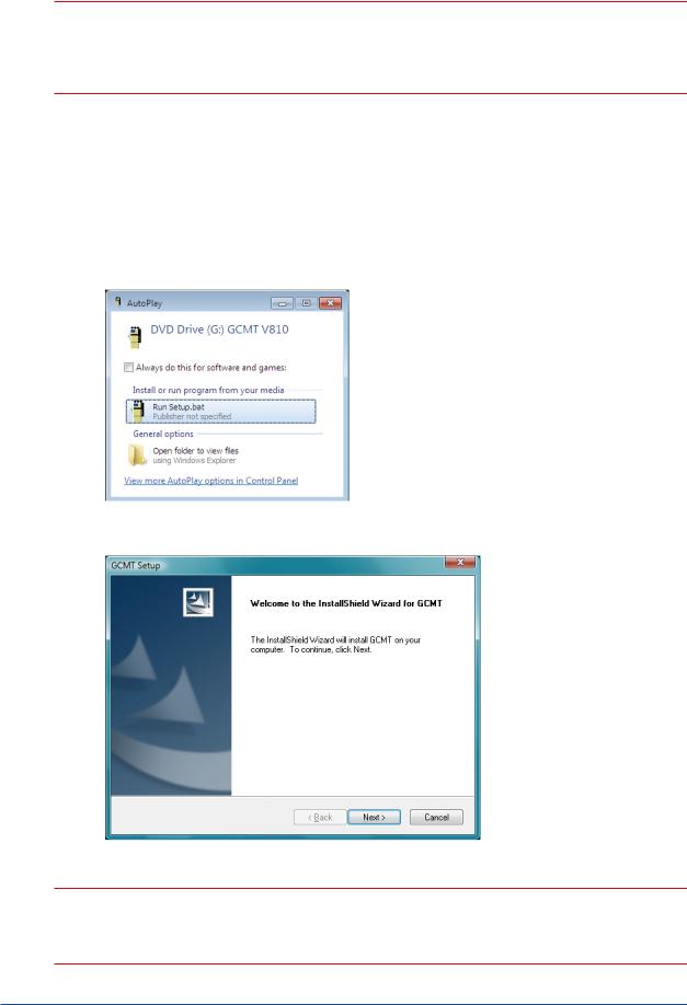
(2)Insert the installation disk into the CD-ROM drive.
(3)The install program is started automatically.
The following dialog box appears. Click [Run Setup.bat].
If it is not started automatically, run “setup.bat” file in the CD-ROM manually.
(4)The “Welcome to the InstallShield Wizard for GC Maintenance Terminal” dialog appears.
Click [Next].
(5) Hereafter, install according to the displayed instruction.
 NOTE
NOTE
Might be necessary to restart the personal computer at the end of installation.
IM 11B03G03-03E 4th Edition : Mar. 21, 2012-00
<Installing the Maintenance Terminal> |
3 |
|
|
n Disabling UAC
User Account Control (UAC) helps prevent unauthorized programs from being installed on the
system silently by viruses or malicious software. This feature is normally preferable, but in some cases, it may interfere with system operation and settings, e.g., UAC may block installation of some applications.
 NOTE
NOTE
UAC can be disabled at the user’s discretion. Yokogawa is not responsible for any problems that may result from disabling UAC.
The UAC setting is enabled by default. To disable the setting, you must log on using an administrator account. All the following steps should be done as an administrator account.
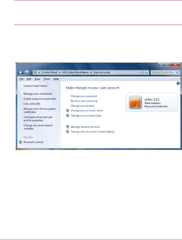
•for Windows 7
(1)Open the Control Panel and then User Accounts.
IM 11B03G03-03E 4th Edition : Mar. 21, 2012-00

<Installing the Maintenance Terminal> |
4 |
|
|
(2) Click [Change User Account Control settings].
(3) Slide to [Never notify], and then click [OK].
Disabling UAC is now complete.
In order to re-enable UAC, slide the above level, and then click [OK].
•for Windows Vista
(1)Open the Control Panel and then User Accounts.
IM 11B03G03-03E 4th Edition : Mar. 21, 2012-00
<Installing the Maintenance Terminal> |
5 |
|
|
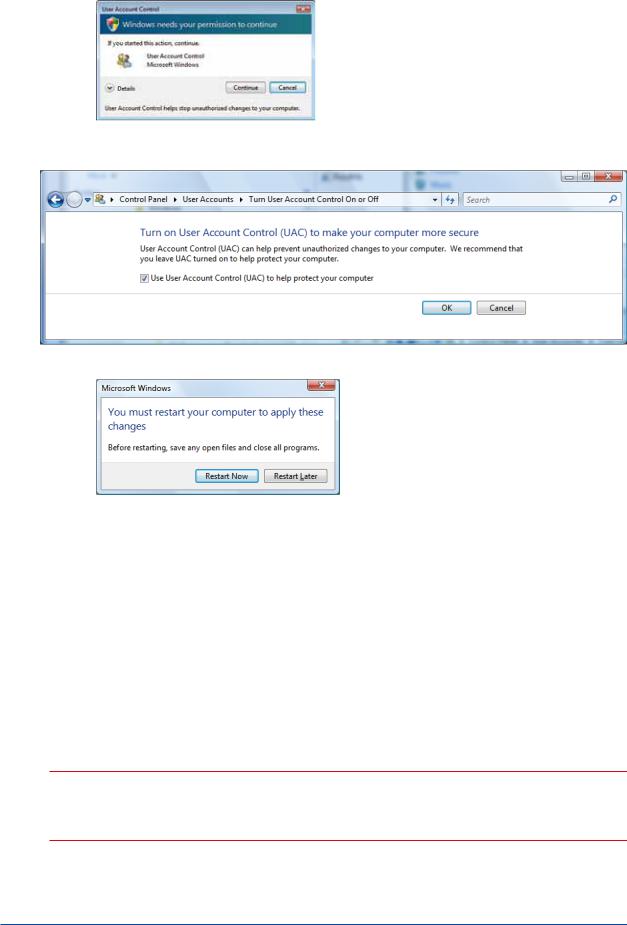
(2)Click [Turn User Account Control on or off]. The following dialog appears. Click [Continue].
(3)The [Turn User Account Control On or Off] dialog appears. Uncheck the [Use User Account
Control (UAC) to help protect your computer] check box, and then click [OK].
(4) The following dialog appears. Click [Restart Now] to restart the computer.
Disabling UAC is now complete.
In order to re-enable UAC, just select the above check box and reboot.
nInstalling GCMT on Computers Running OSs Other Than Windows 7 or Windows Vista
(1)Prepare a personal computer which fills the specification and turn on the power.
Start Windows.
(2)Insert the installation disk into the CD-ROM drive.
(3)The install program is started automatically.
The steps after this are the same as those for installing on computers running Windows 7 OS.
 NOTE
NOTE
Might be necessary to restart the personal computer at the end of installation.
IM 11B03G03-03E 4th Edition : Mar. 21, 2012-00

<Installing the Maintenance Terminal> |
6 |
|
|
n PC Configuration for Power Management
It is recommended that the following items be set and confirmed after installation of GCMT.
 NOTE
NOTE
GCMT may not function properly while the sleep, standby and hibernation settings are enabled. The settings above can be disabled in Windows. The setting procedure is as follows.
• for Windows 7
Log on as a user with administrator privileges, click the Start menu, select Control Panel, Hardware and Sound, double-click Power Options to display the Power Options Properties dialog box, and then make sure the following items are set as described below. Note that some of the items described below may not be displayed depending on the configuration of the PC. If an item is not displayed, the function is disabled.
•Choose what the power button does.
When I press the power button: Do nothing When I press the sleep button: Do nothing When I close the lid: Do nothing
•Choose what to turn off the display
Turn off the display: Never
• for Windows Vista
Log on as a user with administrator privileges, click the Start menu, select Control Panel, doubleclick Power Options to display the Power Options Properties dialog box, and then make sure the following items are set as described below. Note that some of the items described below may not be displayed depending on the configuration of the PC. If an item is not displayed, the function is disabled.
•System Settings window
When I press the power button: Do nothing When I press the sleep button: Do nothing When I close the lid: Do nothing
•Edit Plan Settings window
Put the computer to sleep: Never
• for Windows XP
Log on as a user with administrator privileges, click the Start menu, select Control Panel, doubleclick Power Options to display the Power Options Properties dialog box, and then make sure the following items are set as described below. Note that some of the items described below may not be displayed depending on the configuration of the PC. If an item is not displayed, the function is disabled.
•Power Schemes Tab
System standby: Disabled System hibernates: Disabled
•Advanced Tab
Some PC keyboards have a sleep button. Disable this key with the following setting in the Power buttons area.
IM 11B03G03-03E 4th Edition : Mar. 21, 2012-00
<Installing the Maintenance Terminal> |
7 |
|
|
When pressing the sleep button on my computer: Do nothing
•Hibernate Tab
Enable hibernation: Unselected
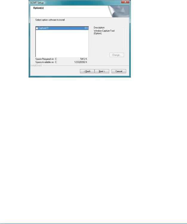
n CaptureIt! Installation
<Use the CaptureIt!>
You can select whether “CaptureIt!” capturing software at a below dialogue box in the installation of GCMT.
You select whether to install “CaptureIt!” in the check column, and click on the “Next” button.
<Not use the CaptureIt!>
(1)Press the Print Screen key on your keyboard to copy the bitmap on the clipboard. It may be labeled [PrtScn].
When you want to capture an active window, press and hold down the “Alt” key, and press the “Print Screen” key on your keyboard to copy the bitmap on the clipboard.
(2)Open an image editing programme, such as Microsoft Paint.
Start the Paint accessory (Start -> Program -> Accessories -> Paint).
(3)Select [PASTE] from the [Edit] menu.
IM 11B03G03-03E 4th Edition : Mar. 21, 2012-00
<Installing the Maintenance Terminal> |
8 |
|
|
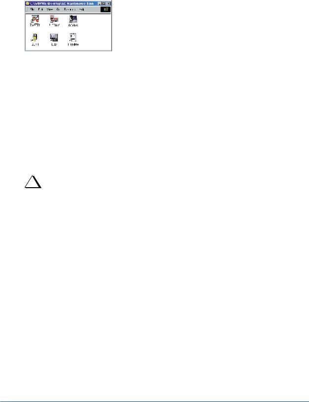
n Changes in the Windows Environment
When the GCMT is installed, the following changes are made to the Windows™ environment.
• “GC Maintenance Terminal” Group
When the GCMT is installed, a new “GC Maintenance Term.” group is registered. In the group, the six icons, “CAPTIT”, “F_CONV”, “GCANA”, “GCMT”, “LCD”, and “ReadMe” are registered.
F09.ai
• GCMT.INI File
When the GCMT is installed, a “GCMT.INI” initialization file is created in the directory where Windows™-executable files are located. However, if a GCMT.INI file already exists because of a previous installation of the GCMT, for example, the installer asks whether to overwrite or not. GCMT.INI contains the following major items of information:
[GC_COMM ] |
|
|
ComPort=1 |
· · · · · · · · · · · · · · |
· · Type the communication port number (typically “1”). |
[ALARM_101 |
· · · · · · · · · · · · · · |
· · Register the text describing a user-defined alarm. |
CODE=101 |
|
|
MESSAGE=#1 REAK CONC. ERR |
|
|
Abnormal concentration of component #1 |
|
|
· · · · · · |
|
|
|
|
|
TIP
About initialization files
•If you are upgrading the version of the Maintenance Terminal already in use or operating the Maintenance
Terminal with the default values, you need not make any changes to the initialization file.
•Changes to the file do not take effect until the system is restarted.
IM 11B03G03-03E 4th Edition : Mar. 21, 2012-00
<Installing the Maintenance Terminal> |
9 |
|
|
nStandard Specifications (Communication Converter K9404LA, K9490LD, RS-232C, Communication cable, Figure, Wiring)
This communication converter converts communications from RS-422 to RS-232C for PC or DCS communication and shuts off the communication signals when a power-off signal is received from the analyzer. This maintains explosion-protection on the analyzer side.
• Signal terminal, to the GC1000 Mark II
M4 terminals
1RS-422 SDA, SDB, RDA, RDB
2D/I 12 V +, -
• Signal Terminals on the Communication Equipment
M4 terminals
RS-232C D-Sub25 female terminals
• Power supply
100 to 240 VAC ±10%, 50/60 Hz ±5%, 15 W Max., M4 terminals
• Terminal Arrangement (common for K9404LA, K9404LD)
|
D-SUB female 25 pins |
|
|
|
|
|
|
|
|
|
Terminal: M4 |
|
|
|
|
|
|
|
|
|
|
|
|
|
|
|
|
|
|
|
|
|
|
|
|
|
|
|
|
|||||||||||||||||||||
|
|
|
|
|
|
|
|
|
|
CN1 |
|
|
|
|
|
|
|
|
|
|
|
|
|
CN3 |
|
|
|
|
|
|
|
|
|
|
|
|
|
|
CN2 |
|||||||||||||||||||||
|
|
|
|
|
|
|
|
|
|
|
|
|
|
|
|
|
|
|
|
|
|
|
|
|
|
|
|
|
|
|
|
|
|
|
|
|
|
|
|
|
|
|
|
|
|
|
|
|
|
|
|
|||||||||
|
|
|
|
|
|
|
|
|
|
|
|
|
|
|
|
|
|
|
|
|
|
|
|
|
|
|
|
|
|
|
|
|
|
|
|
|
|
|
|
|
|
|
|
|
|
|
|
|
|
|
|
|
|
|
|
|
|
|
|
|
|
|
|
|
|
|
|
|
|
|
|
|
|
|
|
|
|
|
|
|
|
|
|
|
|
|
|
|
|
|
|
|
|
|
|
|
|
|
|
|
|
|
|
|
|
|
|
|
|
|
|
|
|
|
|
|
|
|
|
|
|
|
|
|
|
|
|
|
|
|
|
|
|
|
|
|
|
|
|
|
|
|
|
|
|
|
|
|
|
|
|
|
|
|
|
|
|
|
|
|
|
|
|
|
|
|
|
|
|
|
|
|
|
|
|
|
|
|
|
|
|
|
|
|
|
|
|
|
|
|
|
|
|
|
|
|
|
|
|
|
|
|
|
|
|
|
|
|
|
|
|
|
|
|
|
|
|
|
|
|
|
|
|
|
|
|
|
|
|
|
|
|
|
|
|
|
|
|
|
|
|
|
|
|
|
|
|
|
|
|
|
RS-232C |
|
|
|
|
|
|
SDA SDB RDA RDB + – |
|
|
|
|
|
|
|
|
|
N L |
|||||||||||||||||||||||||||||||||||
|
|
|
|
|
|
|
|
|
|
|
|
|
|
|
|
|
|
|
|
|
|
|||||||||||||||||||||||||||||||||||||||
|
|
|
|
|
|
|
|
|
|
|
|
|
|
|
|
|
|
|
|
|
|
|
|
|
|
|
|
|
|
|
|
|
|
|
|
|
|
|
|
|
|
|
|
|
|
|
|
|
|
|
|
|
|
|
|
|
|
|
||
|
|
|
|
|
|
|
|
|
|
|
|
|
|
|
|
|
|
|
|
|
|
|
|
|
|
|
|
|
|
|
|
|
|
|
|
|
|
|
|
|
|
|
|
|
|
|
|
|
|
|
|
|
|
|
|
|
|
|||
|
|
|
|
|
|
|
|
|
|
|
|
|
|
|
|
|
|
|
|
|
|
RS-422 |
D/I 12V |
AC power supply |
||||||||||||||||||||||||||||||||||||
|
|
|
|
|
|
|
|
|
|
|
|
|
|
|
|
|
|
from the GC1000 analyzer |
|
|
|
|
|
|
|
|
|
|
|
|
F10.EPS |
|||||||||||||||||||||||||||||
|
|
|
|
|
|
|
|
|
|
|
|
|
|
|
|
|
|
|
|
|
|
|
|
|
|
|
|
|
|
|
|
|
|
|
|
|
|
|
|
|
|
|
|
|
|
|
|
|
|
|
|
|
|
|
||||||
• PC Communication Cable (Straight type) |
|
|
|
|
|
|
|
|
|
|
|
|
|
|
|
|
|
|
|
|
|
|
|
|
|
|
|
|
||||||||||||||||||||||||||||||||
|
|
|
|
|
|
|
|
Internal wiring |
|
|
|
|
|
|
|
|
|
|
|
|
|
|
|
|
|
|
|
|
|
|
|
|
|
|
|
|
|
|
|
|
|
|
|
|
|
|
|
|
|
|
|
|
|
|
|
|
|
|
|
|
|
FG |
GND |
|
|
|
|
|
|
|
|
|
|
|
|
|
GND |
|
|
|
|
|
|
|
|
|
|
|
|
|
|
|
|
|
|
|
|
|
|
|
|
|
|
|
|
|
|
|
|
|
|
|
|
||||||||
|
|
|
|
|
|
|
|
|
|
|
|
|
|
|
|
|
|
|
|
|
|
|
|
|
|
|
|
|
|
|
|
|
|
|
|
|
|
|
|
|
|
|
|
|
|
|
|
|
|
|||||||||||
|
1 |
|
|
|
|
|
|
|
|
|
|
|
|
|
1 |
|
CD |
|
|
|
|
|
|
|
|
|
|
|
|
|
|
|
|
|
|
|
|
|
|
|
|
|
|
|
|
|||||||||||||||
|
|
|
|
|
|
|
|
|
|
|
|
|
|
|
|
|
|
|
|
|
|
|
|
|
|
|
|
|
|
|
|
|
|
|
|
|
|
|
|
|
|
|
||||||||||||||||||
|
CD |
8 |
|
|
|
|
|
|
|
|
|
|
|
|
|
|
|
|
|
|
|
|
|
|
|
|
|
|
|
|
|
|
|
|
||||||||||||||||||||||||||
|
|
|
|
|
|
|
|
|
|
|
|
|
|
|
|
|
|
|
|
|
|
|
|
|
|
|
|
|
|
|
|
|
||||||||||||||||||||||||||||
|
RD |
3 |
|
|
|
2 |
|
RD |
|
|
|
|
|
|
|
|
|
|
|
|
|
|
|
|
|
|
|
|
|
|
|
|
|
|
|
|
||||||||||||||||||||||||
|
|
|
|
|
|
|
|
|
|
|
|
|
|
|
|
|
|
|
|
|
|
|
|
|
|
|
|
|
|
|
|
|
||||||||||||||||||||||||||||
|
SD |
2 |
|
|
|
3 |
|
SD |
|
|
|
|
|
|
|
|
|
|
|
|
|
|
|
|
|
|
|
|
|
|
|
|
|
|
|
|
||||||||||||||||||||||||
|
|
|
|
|
|
|
|
|
|
|
|
|
|
|
|
|
|
|
|
|
|
|
|
|
|
|
|
|
|
|
|
|
||||||||||||||||||||||||||||
|
ER |
20 |
|
|
|
4 |
|
ER |
|
|
|
|
|
|
|
|
|
|
|
|
|
|
|
|
|
|
|
|
|
|
|
|
|
|
|
|
||||||||||||||||||||||||
|
|
|
|
|
|
|
|
|
|
|
|
|
|
|
|
|
|
|
|
|
|
|
|
|
|
|
|
|
|
|
|
|
||||||||||||||||||||||||||||
|
SG |
7 |
|
|
|
5 |
|
SG |
|
|
|
|
|
|
|
|
|
|
|
|
|
|
|
|
|
|
|
|
|
|
|
|
|
|
|
|
||||||||||||||||||||||||
|
|
|
|
|
|
|
|
|
|
|
|
|
|
|
|
|
|
|
|
|
|
|
|
|
|
|
|
|
|
|
|
|
||||||||||||||||||||||||||||
|
DR |
6 |
|
|
|
6 |
|
DR |
|
|
|
|
|
|
|
|
|
|
|
|
|
|
|
|
|
|
|
|
|
|
|
|
|
|
|
|
||||||||||||||||||||||||
|
|
|
|
|
|
|
|
|
|
|
|
|
|
|
|
|
|
|
|
|
|
|
|
|
|
|
|
|
|
|
|
|
||||||||||||||||||||||||||||
|
RS |
4 |
|
|
|
7 |
|
RS |
|
|
|
|
|
|
|
|
|
|
|
|
|
|
|
|
|
|
|
|
|
|
|
|
|
|
|
|
||||||||||||||||||||||||
|
|
|
|
|
|
|
|
|
|
|
|
|
|
|
|
|
|
|
|
|
|
|
|
|
|
|
|
|
|
|
|
|
||||||||||||||||||||||||||||
|
CS |
5 |
|
|
|
8 |
|
CS |
|
|
|
|
|
|
|
|
|
|
|
|
|
|
|
|
|
|
|
|
|
|
|
|
|
|
|
|
||||||||||||||||||||||||
|
|
|
|
|
|
|
|
|
|
|
|
|
|
|
|
|
|
|
|
|
|
|
|
|
|
|
|
|
|
|
|
|
||||||||||||||||||||||||||||
|
|
|
CI |
22 |
|
|
|
9 |
|
CI |
|
|
|
|
|
|
|
|
|
|
|
|
|
|
|
|
|
|
|
|
|
|
|
|
|
|
|
|
||||||||||||||||||||||
|
|
|
|
|
|
|
|
|
|
|
|
|
|
|
|
|
|
|
|
|
|
|
|
|
|
|
|
|
|
|
|
|
|
|
||||||||||||||||||||||||||
|
|
|
|
|
|
K9404LA |
|
|
|
|
|
|
Personal computer |
|
|
|
|
|
|
|
|
|
|
|
|
|
|
|
|
|
|
|
|
|
|
|
|
|
|
|
|
|||||||||||||||||||
F12.ai
IM 11B03G03-03E 4th Edition : Mar. 21, 2012-00
|
|
|
|
|
|
<Installing the Maintenance Terminal> |
10 |
||||
|
|
|
|
|
|
|
|
|
|
|
|
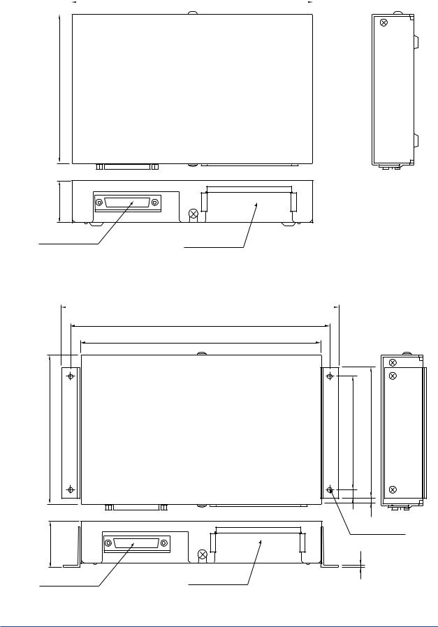
• External Dimensions (K9404LA) |
|
|
|
||||||||
|
|
|
203 |
|
|
|
Unit: mm |
||||
|
|
|
|
|
|
|
|||||
|
|
|
|
|
|
|
|
|
|
|
|
126
35 |
|
|
|
|
|
Weight: approximately 2 kg |
|
RS-232C |
RS-422, D/I 12 V |
|
|
D-SUB 25P Socket |
F11.ai |
||
Power supply |
|||
|
|
• External Dimensions (K9404LD)
233 |
Unit: mm |
|
218
203
126 |
96 |
110 |
7
|
5 |
|
4-ø4.5 |
40 |
Mounting holes |
|
|
|
1.6 |
RS-232C |
RS-422, D/I 12 V |
Weight: approximately 2 kg |
|
D-SUB 25P Socket |
Power supply |
||
|
K9404LD.ai
IM 11B03G03-03E 4th Edition : Mar. 21, 2012-00
<Installing the Maintenance Terminal> |
11 |
|
|
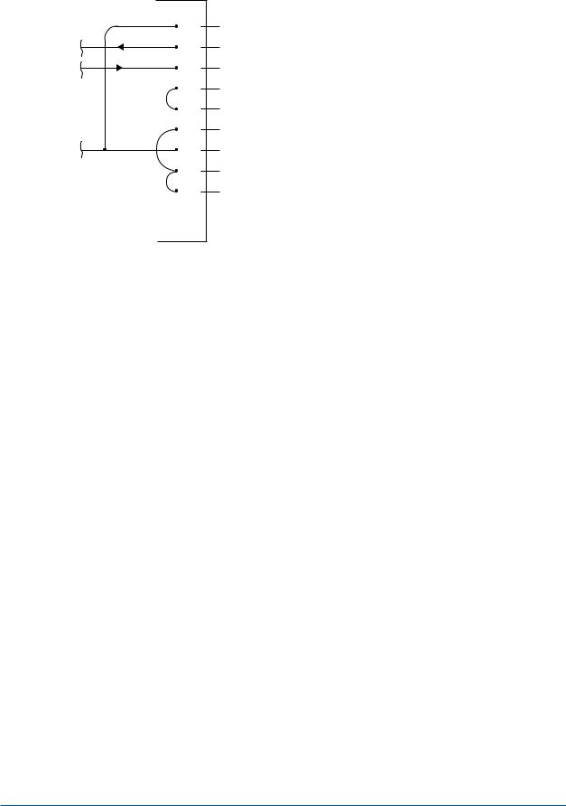
• Terminal RS-232C: Wiring in the inside of converter (K9404LA, K9404LD)
RS-232C |
Wiring in the inside of converter |
FG 1
SD 2
RD 3
RS 4
CS 5 Outside
DR 6
SG 7
CD 8
ER 20
Other pins are open.
RS-232C.ai .
IM 11B03G03-03E 4th Edition : Mar. 21, 2012-00

Blank Page
<1. Overview of Maintenance Terminal> |
1-1 |
1.Overview of Maintenance Terminal
This chapter provides an overview of the Maintenance Terminal and basic information required to operate the package.
1.1How the Maintenance Terminal Works
In this section, you will learn how the Maintenance Terminal software package works before you start using it.
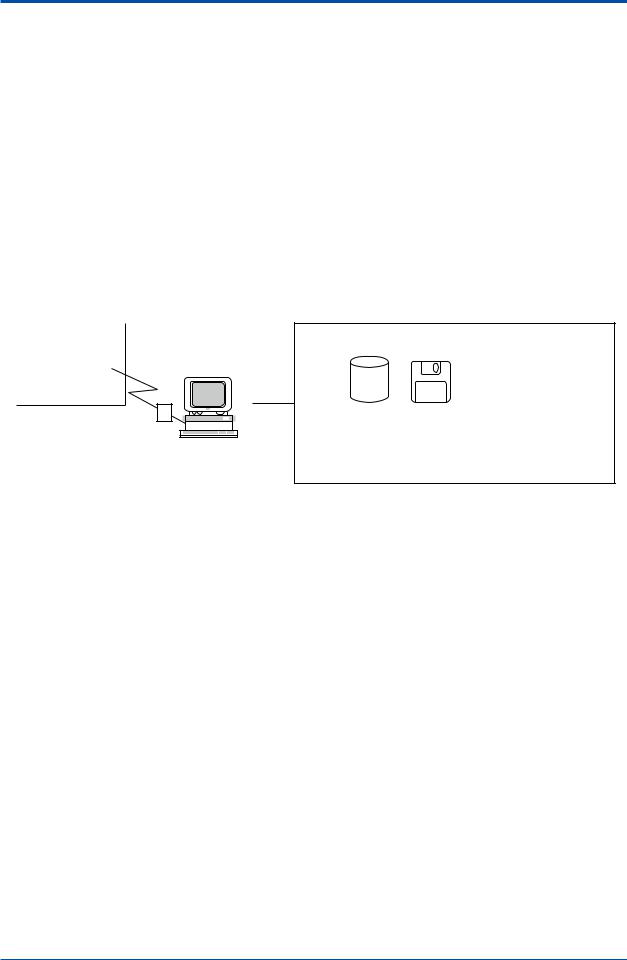
n What Is the Maintenance Terminal?
The Maintenance Terminal (GCMT) is a software package used to monitor and maintain the GC1000 Mark II analyzer (hereinafter referred to as the “analyzer”) on a personal computer by linking the computer to the analyzer through a communication line. The figure below illustrates an overview of the Maintenance Terminal.
Field |
Instrument room/office |
|
GC1000 Mark II |
|
|
analyzer |
|
Personal computer |
|
||
|
|
|
|
|
|
RS-422/RS-232C converter
Analyzer monitoring and maintenance
Disk |
Printer |
|
|
|
|
|
|
|
|
|
|
|
|
|
|
• The Maintenance Terminal reads |
• The Maintenance |
chromatograms and analysis |
Terminal sends |
results and saves them on disks. |
chromatograms and |
• The Maintenance Terminal reads |
analysis results to a |
and writes parameter settings. |
printer. |
F0101.ai
n Features of the Maintenance Terminal
The Maintenance Terminal features:
• Remote Operation of LCD Panel
The LCD screen of the analyzer is duplicated onto the CRT screen of your personal computer.
Thus, you can manipulate the LCD screen from a location distant from the field.
• Analyzer Operation Window Presenting an Overall View
The current operation mode, valve and detector statuses, and a chromatogram are displayed in one window (Analyzer Operation window). This gives a convenient view of the operating status at a glance. Just click on an object in the window to change the mode, open and close valves, view the detailed chromatogram, etc.
• Uploading and Downloading Analyzer Parameter Settings
Parameter settings can be uploaded and downloaded, thus allowing the parameters set on the LCD panel to be also set in another analyzer.
• Detailed Chromatogram Display and Data Saving
Achromatogram is displayed in two ways: theAnalyzer Operation window which shows an overview of the chromatogram and the Chromatogram window which provides a more
detailed view of it. The Chromatogram window allows zooming, changing scales, and saving of chromatogram data.
IM 11B03G03-03E 4th Edition : Mar. 21, 2012-00
<1. Overview of Maintenance Terminal> |
1-2 |
|
|
• Analysis Data Accumulation and Graph Creation
The results of analyses at the analyzer are gathered on an analysis history sheet. One history sheet can hold the peak names of up to 255 analyses and analysis time data of 250 analyses. The analysis history sheet can be saved, retrieved or graphed. In addition, the sheet can be retrieved as a file format in Microsoft Excel™ for further advanced data processing.
• Data Acquisition for Maintenance
Personal computers and Windows™ have been designed with the assumption that they will be used in a general office environment. Therefore, the Maintenance Terminal is aimed for use on a daily basis in maintaining the analyzer. For continuous monitoring over a long period, it is
recommended that the process instruments be used for analog output, DCS communication and as an analyzer bus server.
1.2Maintenance Terminal Group in Program
Manager
In this section, you will learn about the types of software composing the Maintenance Terminal group and the windows configuring the Maintenance Terminal.
n Software Configuration
The Maintenance Terminal is composed of the following five types of software:
Software |
Function |
|
|
LCD emulator (LCD) |
This software functions independent of the Maintenance Terminal. It can |
|
emulate (i.e., work in the same way as) the analyzer LCD panel, allowing the |
|
operator to control the analyzer panel from a personal computer. |
Maintenance |
The main section of the Maintenance Terminal software package. It bases most |
Terminal (GCMT) |
of its functions on the Analyzer Operation window which allows you to view the |
|
analyzer status and operate the analyzer. |
Analysis result panel |
This panel stores the results of analysis. It is started automatically when the |
(GCANA) |
Maintenance Terminal is activated. |
CAPTURE IT! |
This is a tool used to make hard copies. For more details, see the manual for |
(CAPTIT) |
CAPTURE IT!. |
GC communication |
The software used to carry out communication between the analyzer and |
control (GCCOMM) |
GCMT. This software starts up as an icon when LCD and GCMT are started. |
|
The program runs in the background and is always invisible to users. |
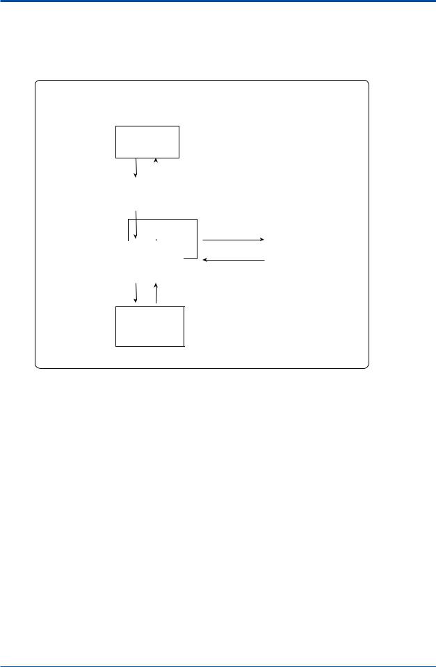
n Maintenance Terminal Window Layout
The Maintenance Terminal is composed of the following four windows:
Window |
Function |
|
|
Analyzer Operation |
The basic Maintenance Terminal window. This displays the analyzer’s latest |
|
status and can be used to perform various operations. |
Chromatogram |
Displays chromatograms in detail. |
Alarm |
Displays alarm statuses in the analyzer. |
Analysis Results |
This sheet automatically starts up when the Maintenance Terminal is started. |
|
It displays the latest analysis results. |
IM 11B03G03-03E 4th Edition : Mar. 21, 2012-00

<1. Overview of Maintenance Terminal> |
1-3 |
|
|
The windows are interrelated as follows:
|
|
|
|
Chromatogram |
|
|
|
|||
|
|
|
|
window |
|
|
|
|||
|
|
|
|
|
|
|
|
|
|
|
|
|
|
|
|
|
|
|
|
|
|
|
|
|
|
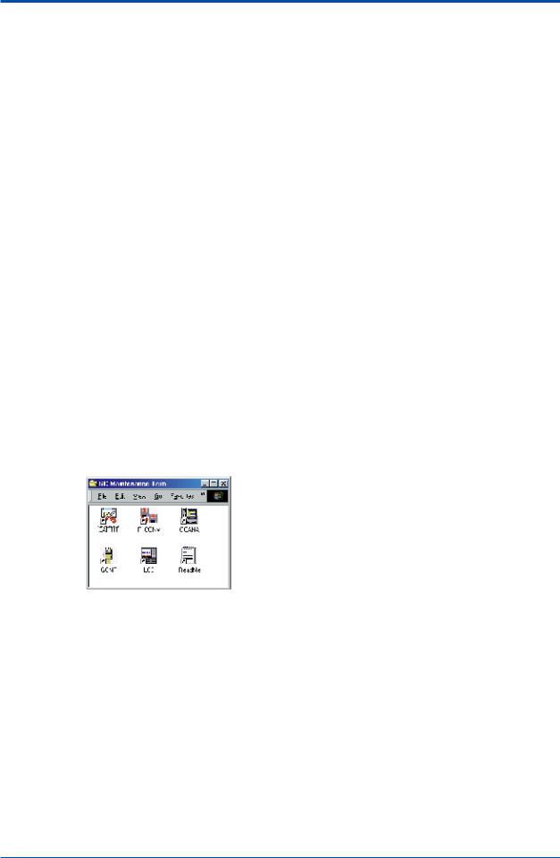
|
|
Alarm Details window |
|
|||
|
|
|
|
|
|
|
|
|
|
|
|
|
|
|
|
Alarm History window |
|
|
|||
|
|
|
|
|
||||||
|
|
|
|
|
|
|
|
|
|
|
Analyzer Operation |
|
|
|
Alarm Status window |
|
|
|
|||
|
|
|
|
|
||||||
window |
|
|
|
|
|
|
|
|
|
|
|
|
|
|
|
|
|
|
|
|
|
|
|
|
|
|
|
|
|
|
|
|
|
|
|
|
|
|
|
Lab Analysis Results |
|||
|
|
|
|
|
|
|
window |
|
||
|
|
|
|
|
|
Retention Time History |
|
|||
|
|
|
|
|
|
|
||||
|
|
|
|
|
|
window |
|
|||
|
|
|
|
|
|
Concentration Analysis |
|
|
||
|
|
|
|
|
|
|
|
|||
|
|
|
|
|
History window |
|
|
|||
|
|
|
|
Latest Analysis |
|
|
||||
|
|
|
|
|
|
|
||||
|
|
|
|
Results window |
|
|||||
|
|
|
|
|||||||
|
|
|
|
|
|
|
|
|
|
|
Alarm-related windows
Analysis Results window
F0102.ai
n Notes on Use
Note the following when using the LCD emulator and the Maintenance Terminal:
• Use this software with the analyzer in the Remote mode.
Unless the analyzer is in the Remote mode, you cannot start the LCD emulator. The display function of the Maintenance Terminal can be used even in the Local mode. But if it is operated, a message appears informing the user that operation is not accepted.
•The LCD emulator and Maintenance Terminal cannot be started at the same time.
Therefore, if you want to use the Maintenance Terminal while the LCD emulator is still running, first quit the LCD emulator and then start the Maintenance Terminal.
n Notes before turning on the power switch
Please confirm all communication cables have been connected before turning on the power switch.
Please turn on power switch in order of the GC1000 MarkII, the communication converter
(K9404LA), and personal computer. Please turn off the power switch by the opposite procedure.
n Notes concerning communication cables
Please do not take off or install the communication cables during the power supply turned on.
If it will be done, it may be needed to turn on the main power again because of communication error when the GCMT is used next time.
IM 11B03G03-03E 4th Edition : Mar. 21, 2012-00
<1. Overview of Maintenance Terminal> |
1-4 |
1.3Notes Before Use
The Maintenance Terminal is a software package which runs under Windows™. In this section, you will learn basic operations common to the Windows™ software.
n Mouse
A mouse is used to work with the Maintenance Terminal.
• Basic Mouse Operations
The mouse cursor ( ) in the window moves as you move the mouse. Place the mouse cursor on an item you want to select in a window and click the left mouse button to select it.
• Buttons
There are three ways to press mouse buttons:
Click: |
Press the left button and immediately remove your finger. Normally, most |
|
clicking operations use the left button, but some may use the right button. |
|
“Click” in this manual means to press the left button. |
Double click: |
Press the left button twice in quick succession. |
Drag: |
Move the mouse from a starting position to an ending position while pressing |
|
down the left button, and then release your finger. This is used, for example, to |
|
select a number of items at once. |
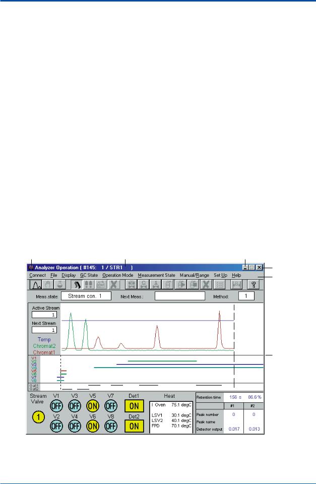
n Window Layout
The figure below illustrates the window layout, using theAnalyzer Operation window as an example.
Control menu box |
Title bar |
Minimize button |
Close button
Menu bar
Border line
F0103.ai
IM 11B03G03-03E 4th Edition : Mar. 21, 2012-00
<1. Overview of Maintenance Terminal> |
1-5 |
|
|
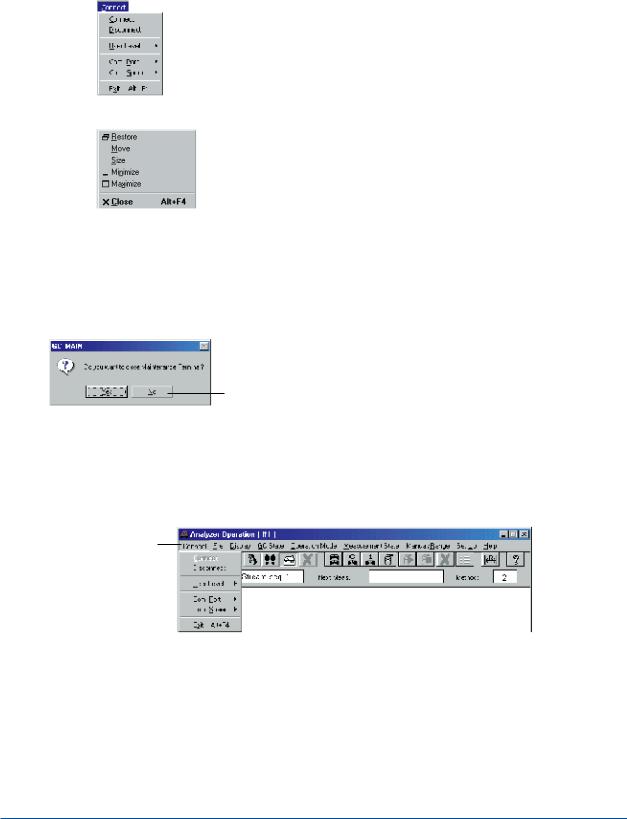
n How to Select Menus • Menus
The menu bar and control menu box contain menu items necessary in working with the Maintenance Terminal.Amenu is a list of classified functions (commands). From a menu, you select a command to be executed.
•[Connect] Menu
F0104.ai
•Control Menu
F0105.ai
• Dialog Box and Buttons
When you select a command from a menu, a dialog box pops up to ask you to specify details about the command. Give the details and then select the appropriate button to execute the command.
Dialog Box to Confirm Termination
Button
F0106.ai
• Procedure
Example: To execute the [Disconnect] command in theAnalyzer Operation window:
(1)Click on [Connect] on the menu bar. The [Connect] menu opens.
Click here.
F0107.ai
•In a menu, selectable commands appear dark.
•The command can also be selected by typing the underlined letter with the [Alt] key held down.
(2)Click on the [Disconnect] command.
Aconfirmation dialog box pops up.
(3)Click on the [OK] button.
The Disconnect command is executed.
IM 11B03G03-03E 4th Edition : Mar. 21, 2012-00
<1. Overview of Maintenance Terminal> |
1-6 |
|
|
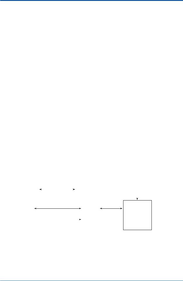
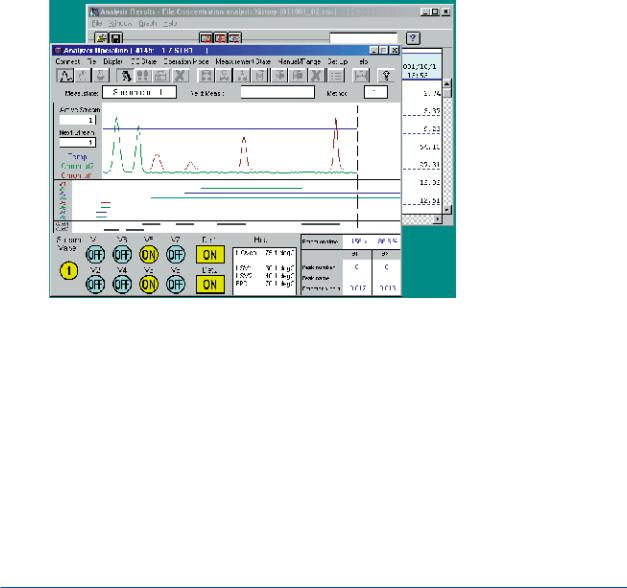
n Multi-windows
The windows of the Maintenance Terminal open in an overlapping manner on top of the Analyzer Operation window. Thus, you can manipulate the windows properly to view multiple windows at the same time.
• Window Operation
In a Maintenance Terminal window, the following operations are possible:
Resizing the window: Drag the window boundary. Only theAnalysis Results windows andAlarm windows can be changed in size.
Minimizing a window to an icon: Click on the minimize button ( ). To return to the original size, double-click on the icon.
• Making the Window Active
The window that is currently operational is called the “active window.” The title bar of the active window appears dark. When more than one window is open, click anywhere within the window you want to work with. The window you click becomes an active window. You can then work with the active window only.
• Example of Multi-windows
F0108.ai
IM 11B03G03-03E 4th Edition : Mar. 21, 2012-00
<2. LCD Emulator Window> |
2-1 |
2.LCD Emulator Window
The LCD emulator reproduces the LCD panel of the analyzer in the Windows™ operating system. The screens and buttons on the LCD panel of the analyzer installed in the field are drawn directly on a Windows™ display, and appear and function exactly the same way as they do on the LCD panel. This chapter outlines the LCD Emulator window. For details, see the GC1000 LCD Window Operation Manual, IM 11B03A03-05E.
• Prior to Operation
Before starting the emulator, always make sure that the:
•Maintenance Terminal is installed in your personal computer.
•analyzer and personal computer are linked through a communication line.
•analyzer is in the Remote mode.
2.1Starting and Exiting the LCD Emulator
This section describes how to start and exit the LCD emulator.
n Starting
When the Maintenance Terminal is running, you cannot start the LCD emulator. Terminate the
Maintenance Terminal before you start the LCD emulator. You also cannot start the LCD emulator unless the analyzer is in the Remote mode. Note that there is only one window from which the LCD emulator can be started.
•Procedure
(1)Turn on the power to the personal computer, start up Windows™, and open the Maintenance Terminal group window of Program Manager.
LCD |
|
emulator icon |
F0201.ai |
|
IM 11B03G03-03E 4th Edition : Mar. 21, 2012-00
<2. LCD Emulator Window> |
2-2 |
|
|
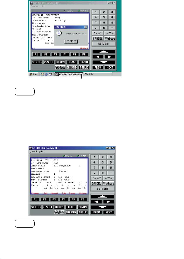
(2)Double-click on the LCD emulator icon.
This establishes a communication link with the analyzer. If the link ends successfully, the
CONNECT lamp of the LCD emulator lights up in green. The dialog box shown below then pops up.
The icon of analyzer communication task. |
F0202.ai |
HELP !
If the window shows the message “Unsuccessful end of connection,” there may be three possible reasons:
(1)The analyzer cannot be connected temporarily via a communication cable due to noise, etc.
Corrective action: Execute the [Connect] command in the [Connect] menu on the menu bar to establish the connection again via the communication cable.
(2)The analyzer is in the Local mode.
Corrective action: Set the analyzer to the Remote mode on the analyzer’s LCD panel and then connect it again via the communication cable.
(3)There is a wrong connection in the wiring to the analyzer.
Corrective action: Check the wiring between the analyzer and your personal computer.
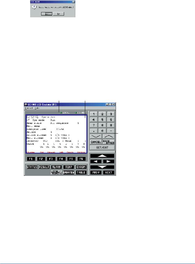
(3)Click on the [OK] button. The LCD Emulator window opens.
F0203.ai
HELP !
When the message “Exit command is received” appears in the LCD emulator window, establish a communication link with the analyzer using the [Connect] command on the [Connect] menu after you have finished panel operation on the analyzer.
IM 11B03G03-03E 4th Edition : Mar. 21, 2012-00
<2. LCD Emulator Window> |
2-3 |
|
|
n Exiting
•Procedure
(1)Click on the [Exit] command in the [Connect] menu.
Adialog box pops up asking you to confirm the termination of the LCD emulator.
F0204.ai
(2)Click on the [Yes] button.
Communication with the analyzer is dropped and the LCD emulator terminates.
(3)Either run other software or terminate Windows™, and then turn off the power.
2.2Basic Operations
The LCD Emulator window is exactly the same as the LCD panel both in appearance and function. Buttons in the window can be operated by using the mouse, or by pressing corresponding keys on the keyboard.
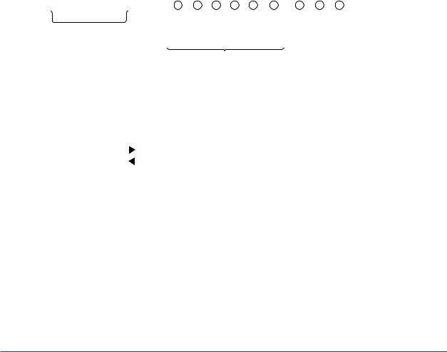
n Window Layout
The following figure shows the LCD Emulator window layout.
LED display area LCD display area
Setting keys
|
|
|
|
|
|
|
|
|
|
|
|
Function keys |
Window switching keys |
F0205.ai |
|||
n Window Operation
• Mouse Operation
Place the mouse cursor on the key to be operated and click the left mouse button. This allows the same key operations as ones on the LCD panel.
• Keyboard Operation
Each window key corresponds to the keys on the keyboard, as shown in the following table. Pressing these keys allows the same key operations as ones on the LCD panel.
IM 11B03G03-03E 4th Edition : Mar. 21, 2012-00

|
|
|
<2. LCD Emulator Window> |
2-4 |
|
|
|
|
|
|
|
Window Keys and Corresponding Keys on Keyboard |
|
||||
|
|
|
|
|
|
|
|
Window Keys |
Keyboard Equivalents |
|
|
|
Function |
[F1] to [F6] |
[F1] to [F6] |
|
|
|
keys |
|
|
|
|
|
Window |
[STATUS] |
[SHIFT] + [F1] |
|
|
|
switching |
[RESULT] |
[SHIFT] + [F2] |
|
|
|
keys |
[ALARM] |
[SHIFT] + [F3] |
|
|
|
|
[TEMP] |
[SHIFT] + [F4] |
|
|
|
|
[CHROM] |
[SHIFT] + [F5] |
|
|
|
|
[LOCAL/REMOTE] |
[SHIFT] + [F6] |
|
|
|
|
[OPERATION] |
[SHIFT] + [F7] |
|
|
|
|
[TABLE] |
[SHIFT] + [F8] |
|
|
|
Setting |
Alphanumeric keys |
Alphanumeric keys |
|
|
|
keys |
[^] [v] |
[Page Down] [Page Up] |
|
|
|
|
[CANCEL] |
[ESC] |
|
|
|
|
[BACK SPACE] |
[BACK SPACE] |
|
|
|
|
[SET/ENT] |
[ENTER] |
|
|
|
|
[^] [<] [>] [v] |
Cursor keys |
|
|
|
|
[PREV] |
[CTRL] + [P] |
|
|
|
|
[NEXT] |
[CTRL] + [N] |
|
|
IM 11B03G03-03E 4th Edition : Mar. 21, 2012-00
<3. Analyzer Operation Window> |
3-1 |
3.Analyzer Operation Window
The Analyzer Operation window opens when the Maintenance Terminal is started. This chapter explains how to open and close this window, how the window is composed, how to change the operation status, and how to upload and download parameter settings.
Windows™ Hierarchy
Program Manager
Maintenance
Terminal group window
|
Startup |
|
|
|
|
||
|
|
|
Termination |
|
|
||
|
Initial Database |
|
|
|
|||
|
Loading window |
|
|
|
|
|
|
|
|
|
|
|
|
[Alarm Status] or |
|
|
|
|
|
|
|
||
|
|
|
|
|
|
[Alarm History] |
|
|
|
Analysis Results |
|||||
|
|
command |
|||||
|
|
window *1 |
|||||
|
|
|
|
||||
|
|
Analyzer |
|
|
|
Alarm window |
|
|
|
Operation window |
|
[Close] command |
|
||
|
|
|
|
|
|
|
|
|
|
|
|
|
|
|
|
[Chromatogram] menu |
[Exit] command |
||||||
Chromatogram window
*1: Appears as an icon
F0301.ai
• Prior to Operation
Before starting up the Maintenance Terminal, always make sure that the:
•Maintenance Terminal has been installed properly in your personal computer.
•analyzer has been connected to your personal computer properly via a communication cable.
IM 11B03G03-03E 4th Edition : Mar. 21, 2012-00
Loading...