


 Loading...
YOKOGAWA F3SP21-0N, F3SP25-2N, F3SP35-5N, F3SP28-3N, F3SP38-6N Manual
...User’s
Manual
Hardware Manual
IM 34M6C11-01E
IM 34M6C11-01E
6th Edition
Yokogawa Electric Corporation

i
Applicable Product:
● Range-free Multi-controller FA-M3
The document number and document model code for this manual are given below.
Refer to the document number in all communications; also refer to the document number or the document model code when purchasing additional copies of this manual.
Document No. |
: |
IM 34M6C11-01E |
Document Model Code |
: |
DOCIM |
Media No. IM 34M6C11-01E (FD) |
6th Edition : May. 2001 (CR) |
IM 34M6C11-01E 6th Edition : May 10, 2001-00 |
All Rights Reserved Copyright 1992, Yokogawa Electric Corporation
ii
Important
„About This Manual
-This Manual should be passed on to the end user.
-Before using the controller, read this manual thoroughly to have a clear understanding of the controller.
-This manual explains the functions of this product, but there is no guarantee that they will suit the particular purpose of the user.
-Under absolutely no circumstances may the contents of this manual be transcribed or copied, in part or in whole, without permission.
-The contents of this manual are subject to change without prior notice.
-Every effort has been made to ensure accuracy in the preparation of this manual. However, should any errors or omissions come to the attention of the user, please contact the nearest Yokogawa Electric representative or sales office.
„Safety Precautions when Using/Maintaining the Product
-The following safety symbols are used on the product as well as in this manual.
Danger. This symbol on the product indicates that the operator must follow the instructions laid out in this instruction manual to avoid the risk of personnel injuries, fatalities, or damage to the instrument. The manual describes what special care the operator must exercise to prevent electrical shock or other dangers that may result in injury or the loss of life.
Protective Ground Terminal. Before using the instrument, be sure to ground this terminal.
Function Ground Terminal. Before using the instrument, be sure to ground this terminal.
Alternating current. Indicates alternating current.
Direct current. Indicates direct current.
IM 34M6C11-01E 6th Edition : May 10, 2001-00

iii
The following symbols are used only in the instruction manual.
 WARNING
Indicates a “Warning”.
Draws attention to information essential to prevent hardware damage, software damage or system failure.
 CAUTION
Indicates a “Caution”
Draws attention to information essential to the understanding of operation and functions.
TIP
Indicates a “TIP”
Gives information that complements the present topic.
SEE ALSO
Indicates a “SEE ALSO” reference.
Identifies a source to which to refer.
-For the protection and safe use of the product and the system controlled by it, be sure to follow the instructions and precautions on safety stated in this manual whenever handling the product. Take special note that if you handle the product in a manner other than prescribed in these instructions, the protection feature of the product may be damaged or impaired. In such cases, Yokogawa cannot guarantee the quality, performance, function and safety of the product.
-When installing protection and/or safety circuits such as lightning protection devices and equipment for the product and control system as well as designing or installing separate protection and/or safety circuits for fool-proof design and fail-safe design of processes and lines using the product and the system controlled by it, the user should implement it using devices and equipment, additional to this product.
-If component parts or consumable are to be replaced, be sure to use parts specified by the company.
-This product is not designed or manufactured to be used in critical applications which directly affect or threaten human lives and safety — such as nuclear power equipment, devices using radioactivity, railway facilities, aviation equipment, air navigation facilities, aviation facilities or medical equipment. If so used, it is the user’s responsibility to include in the system additional equipment and devices that ensure personnel safety.
-Do not attempt to modify the product.
„Exemption from Responsibility
-Yokogawa Electric Corporation (hereinafter simply referred to as Yokogawa Electric) makes no warranties regarding the product except those stated in the WARRANTY that is provided separately.
-Yokogawa Electric assumes no liability to any party for any loss or damage, direct or indirect, caused by the user or any unpredictable defect of the product.
IM 34M6C11-01E 6th Edition : May 10, 2001-00

iv
„Software Supplied by the Company
-Yokogawa Electric makes no other warranties expressed or implied except as provided in its warranty clause for software supplied by the company.
-Use the software with one computer only. You must purchase another copy of the software for use with each additional computer.
-Copying the software for any purposes other than backup is strictly prohibited.
-Store the original media, such as floppy disks, that contain the software in a safe place.
-Reverse engineering, such as decompiling of the software, is strictly prohibited.
-No portion of the software supplied by Yokogawa Electric may be transferred, exchanged, or sublet or leased for use by any third party without prior permission by Yokogawa Electric.
IM 34M6C11-01E 6th Edition : May 10, 2001-00

v
„General Requirements for Using the FA-M3 Controller
●Avoid installing the FA-M3 controller in the following locations:
-Where the instrument will be exposed to direct sunlight, or where the operating temperature exceeds the range 0°C to 55°C (0°F to 131°F).
-Where the relative humidity is outside the range 10 to 90%, or where sudden temperature changes may occur and cause condensation.
-Where corrosive or flammable gases are present.
-Where the instrument will be exposed to direct mechanical vibration or shock.
-Where the instrument may be exposed to extreme levels of radioactivity.
●Use the correct types of wire for external wiring:
-Use copper wire with temperature ratings greater than 75°C.
●Securely tighten screws:
-Securely tighten module mounting screws and terminal screws to avoid problems such as faulty operation.
-Tighten terminal block screws with the correct tightening torque as given in this manual.
●Securely lock connecting cables:
-Securely lock the connectors of cables, and check them thoroughly before turning on the power.
●Interlock with emergency-stop circuitry using external relays:
-Equipment incorporating the FA-M3 controller must be furnished with emergency-stop circuitry that uses external relays. This circuitry should be set up to interlock correctly with controller status (stop/run).
●Ground for low impedance:
-For safety reasons, connect the [FG] grounding terminal to a Japanese Industrial Standards (JIS) Class 3 Ground. For compliance to CE Marking, use cables such as twisted cables which can ensure low impedance even at high frequencies for grounding.
●Configure and route cables with noise control considerations:
-Perform installation and wiring that segregates system parts that may likely become noise sources and system parts that are susceptible to noise. Segregation can be achieved by measures such as segregating by distance, installing a filter or segregating the grounding system.
●Configure for CE Marking Conformance:
-For compliance to CE Marking, perform installation and cable routing according to the description on compliance to CE Marking in the “Hardware Manual” (IM34M6C11-01E).
●Keep spare parts on hand:
-Stock up on maintenance parts including spare modules, in advance.
IM 34M6C11-01E 6th Edition : May 10, 2001-00

vi
●Discharge static electricity before operating the system:
-Because static charge can accumulate in dry conditions, first touch grounded metal to discharge any static electricity before touching the system.
●Never use solvents such as paint thinner for cleaning:
-Gently clean the surfaces of the FA-M3 controller with a cloth that has been soaked in water or a neutral detergent and wringed.
-Do not use volatile solvents such as benzine or paint thinner or chemicals for cleaning, as they may cause deformity, discoloration, or malfunctioning.
●Avoid storing the FA-M3 controller in places with high temperature or humidity:
-Since the CPU module has a built-in battery, avoid storage in places with high temperature or humidity.
-Since the service life of the battery is drastically reduced by exposure to high temperatures, take special care (storage temperature should be from –20 °C to 75°C).
-There is a built-in lithium battery in a CPU module and temperature control module which serves as backup power supply for programs, device information and configuration information. The service life of this battery is more than 10 years in standby mode at room temperature. Take note that the service life of the battery may be shortened when installed or stored at locations of extreme low or high temperatures. Therefore, we recommend that modules with built-in batteries be stored at room temperature.
●Always turn off the power before installing or removing modules:
-Failing to turn off the power supply when installing or removing modules, may result in damage.
●Do not touch components in the module:
-In some modules you can remove the right-side cover and install ROM packs or change switch settings. While doing this, do not touch any components on the printed-circuit board, otherwise components may be damaged and modules may fail to work.
IM 34M6C11-01E 6th Edition : May 10, 2001-00

vii
Introduction
„ Overview of the Manual
This manual explains the configuration, specifications and installation of the Range-Free Multi-controller FA-M3. It also discusses the individual specifications of power supply modules, base modules, I/O modules, cables and terminal block units.
„ Configuration of the Manual
This manual consists of two parts.
z Part A Standard Version
The main part of this manual explains all the details of the FA-M3 system except for those of the FA-M3 Value version.
z Part B FA-M3 Value (F3SC21-1N) Version
The second part of the manual discusses the details specific to the FA-M3 Value (F3SC21-1N).
Chapters A3 (Installation and Wiring), A4 (Test Runs and Troubleshooting) and A5 (Maintenance and Inspection) are common to both the standard FA-M3 and the FA-M3 Value. Be sure to read these chapters before using the FA-M3 Value.
„Other Instruction Manuals
-For products other than the power supply module, base module, I/O module, cable and terminal block unit, refer to their respective manuals.
„Trademarks
-Microsoft Windows, Windows 95, Windows 98 and Windows NT are registered trademarks of Microsoft Corporation, USA.
-Ethernet is a registered trademark of XEROX Corporation.
-The trade and company names that are referred to in this document are either trademarks or registered trademarks of their respective companies.
IM 34M6C11-01E 6th Edition : May 10, 2001-00

Blank Page

TOC-1
FA-M3
Hardware Manual
IM 34M6C11-02E 6th Edition
CONTENTS
Applicable Product:................................................................................... |
i |
||
Important |
................................................................................................... |
ii |
|
Introduction............................................................................................. |
vii |
||
A1. |
System ...............................................................Configuration |
A1-1 |
|
|
A1.1 ........................................................................... |
System Configuration |
A1-1 |
|
A1.2 ...................................................... |
Restrictions on Installing Modules |
A1-3 |
|
A1.3 |
Peripheral Tools Supporting the Program Development of |
|
|
...................................................................................................... |
FA - M3 |
A1-7 |
A2. |
Specifications .............................................and Configuration |
A2-1 |
|
|
A2.1 ........................................................................................ |
Specifications |
A2-1 |
|
A2.2 .......................................................... |
FA - M3 Controller Configuration |
A2-2 |
|
A2.3 ......................................................................... |
Power Supply Modules |
A2-9 |
|
A2.4 ...................................................................................... |
Base Modules |
A2-13 |
|
A2.5 .......................................................................................... |
I/O Modules |
A2-14 |
(1) |
F3XH04-3N High-speed Input Module....................................... |
A2-16 |
(2) |
F3XA08-1N/F3XA08-2N AC Input Modules............................... |
A2-21 |
(3) |
F3XC08-0N No-voltage Contact Input Module .......................... |
A2-23 |
(4) |
F3XD08-6F DC Input Module .................................................... |
A2-24 |
(5) |
F3XD16-3F/F3XD16-4F/F3XD16-3H DC Input Modules........... |
A2-25 |
(6) |
F3XD32-3F/F3XD32-4F/F3XD32-5F DC Input Modules ........... |
A2-27 |
(7) |
F3XD64-3F/F3XD64-4F DC Input Modules............................... |
A2-29 |
(8) |
F3XD08-6N DC Input Module .................................................... |
A2-31 |
(9) |
F3XD16-3N/F3XD16-4N DC-Input Modules.............................. |
A2-33 |
(10) |
F3XD32-3N/F3XD32-4N/F3XD32-5N DC Input Modules.......... |
A2-35 |
(11) |
F3XD64-3N/F3XD64-4N DC Input Modules .............................. |
A2-37 |
(12) |
F3XD64-6M DC Input Module.................................................... |
A2-39 |
(13) |
F3YD04-7N Transistor Output Module ...................................... |
A2-40 |
(14) |
F3YA08-2N Triac Output Module ............................................... |
A2-42 |
(15) |
F3YC08-0C/F3YC08-0N Relay Output Module ........................ |
A2-44 |
(16) |
F3YD08-6A/F3YD08-6B Transistor Output Modules ................. |
A2-46 |
(17) |
F3YD14-5A/F3YD14-5B Transistor Output Modules ................. |
A2-48 |
(18) |
F3YC16-0N Relay Output Module ............................................. |
A2-50 |
(19) |
F3YD32-1A/F3YD32-1B Transistor Output Modules ................. |
A2-52 |
(20) |
F3YD32-1T TTL Output Module................................................. |
A2-54 |
IM 34M6C11-01E 6th Edition : May 10, 2001-00
|
|
|
|
TOC-2 |
|
|
(21) F3YD64-1F Transistor Output Module....................................... |
A2-56 |
|
|
|
(22) |
F3YD64-1A Transistor Output Module....................................... |
A2-58 |
|
|
(23) F3YD64-1M Transistor Output Module ...................................... |
A2-60 |
|
|
|
(24) |
F3WD64-3F/F3WD64-4F Input/Output Modules ....................... |
A2-62 |
|
|
(25) |
F3WD64-3N/F3WD64-4N Input/output Modules ....................... |
A2-66 |
|
A2.6 |
ROM Packs .......................................................................................... |
A2-70 |
|
|
A2.7 |
Cables................................................................................................... |
A2-72 |
|
|
|
(1) Cables for Programming Tool .................................................... |
A2-72 |
|
|
|
(2) CPU Port/9-pin D-sub Adapter Cable ........................................ |
A2-73 |
|
|
|
(3) Cables for Connector Terminal Blocks....................................... |
A2-74 |
|
|
|
(4) |
Fiber-Optic Cord ........................................................................ |
A2-75 |
|
|
(5) |
Fiber-optic Cables...................................................................... |
A2-76 |
|
A2.8 |
Terminal Block Unit and Connector Terminal Block ...................... |
A2-78 |
|
|
|
(1) |
TA40-0N Terminal Block Unit ..................................................... |
A2-78 |
|
|
(2) TA50-0N/TA50-1N Connector Terminal Block............................ |
A2-81 |
|
|
|
(3) |
TA60-0N .................................................................................... |
A2-83 |
|
A2.9 |
Module Current Consumption Tables ............................................... |
A2-85 |
|
|
A2.10 |
External Power Supply ....................................................................... |
A2-88 |
|
|
A2.11 |
External Dimensions........................................................................... |
A2-89 |
|
A3. |
Installation and Wiring............................................................... |
A3-1 |
||
|
A3.1 |
Environmental Conditions for Installation within a |
|
|
|
|
Panel Enclosure .................................................................................... |
A3-1 |
|
|
A3.2 |
Methods for Mounting the FA-M3 within a Panel Enclosure ........... |
A3-3 |
|
|
A3.3 |
System Design Considerations ......................................................... |
A3-10 |
|
|
A3.4 |
Noise Control Considerations ........................................................... |
A3-19 |
|
|
A3.5 |
Wiring the Power Supply Module ...................................................... |
A3-21 |
|
|
A3.6 |
Wiring I/O Modules.............................................................................. |
A3-24 |
|
|
A3.7 |
External Cable Routing Requirements.............................................. |
A3-32 |
|
|
A3.8 |
Calculating Power Consumption....................................................... |
A3-33 |
|
|
A3.9 |
CE Marking Conformance .................................................................. |
A3-34 |
|
A4 |
Test Runs and Troubleshooting................................................ |
A4-1 |
||
|
A4.1 |
Test Run Procedure .............................................................................. |
A4-1 |
|
|
A4.2 |
Test Run Precautions ........................................................................... |
A4-2 |
|
|
A4.3 |
Self-diagnostic Functions .................................................................... |
A4-3 |
|
|
A4.4 |
Troubleshooting Procedure ................................................................. |
A4-9 |
|
|
A4.5 |
CPU Module Reset and Memory Clearance........................................ |
A4-9 |
|
A5 |
Maintenance and Inspection ..................................................... |
A5-1 |
||
|
A5.1 |
Replacing I/O Modules.......................................................................... |
A5-1 |
|
|
A5.2 |
Routine Inspection................................................................................ |
A5-2 |
|
IM 34M6C11-01E 6th Edition : May 10, 2001-00

|
|
TOC-3 |
Appendix A1 System-wide Restrictions on |
|
|
Module Installation............................................ |
Appx.A1-1 |
|
Appendix A1.1 Checking Compliance with Restrictions on |
|
|
|
Module Installation........................................................ |
Appx.A1-1 |
Appendix A1.2 |
Restrictions due to the Number of Slots.................... |
Appx.A1-4 |
Appendix A1.3 |
Restrictions due to the Size of Data Area .................. |
Appx.A1-5 |
Appendix A1.4 |
Restrictions due to the Type of CPU Module ............. |
Appx.A1-7 |
FA-M3 Value (F3SC21-1N)
B1. |
System Configuration................................................................ |
B1-1 |
|
|
B1.1 |
System Configuration........................................................................... |
B1-1 |
|
B1.2 |
Restrictions on Module Installation .................................................... |
B1-2 |
|
B1.3 |
Peripheral Tools Supporting the Program Development of |
|
|
|
FA-M3...................................................................................................... |
B1-3 |
B2. |
Specifications and Configuration ............................................. |
B2-1 |
|
|
B2.1 |
Specifications........................................................................................ |
B2-1 |
|
B2.2 |
System Configuration........................................................................... |
B2-2 |
|
B2.3 |
Sequence CPU Module......................................................................... |
B2-3 |
Revision Information................................................................................. |
i |
||
IM 34M6C11-01E 6th Edition : May 10, 2001-00

Blank Page
A1-1
A1. System Configuration
A1.1 System Configuration
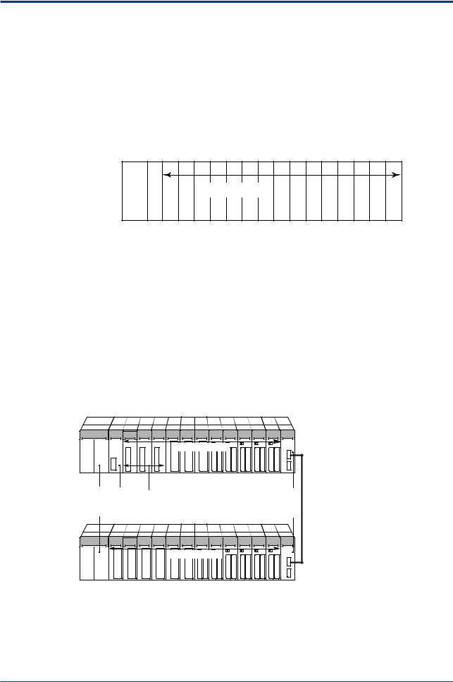
„ Basic Configuration
Figure A1.1 shows the location of slots for installing CPU and I/O modules. A slot number consists of three digits of which the third digit is the unit number.
module |
001 002 003 004 005 006 007 008 009 010 011 012 013 014 015 016 |
|
P |
|
|
|
C |
|
Main unit |
U |
I/O modules |
Powersupply |
|
|
|
|
FA010101.VSD |
Figure A1.1 Slot Numbering
„ Concept of Unit
z Main Unit
A unit in which a CPU module is installed is referred to as a main unit. Thus a main unit is comprised of only one unit.
z Subunit
Subunits are used to increase the number of I/O ports. A maximum of seven subunits can be added to the system to deal with up to 8192 (depending on the CPU module model) I/O points.
Unit |
I/O modules |
|
Main |
||
|
|
1 |
2 |
3 |
4 |
5 |
6 |
7 |
8 |
9 |
10 |
11 |
12 |
13 |
|
Power |
CPU |
Add-on CPU module |
|
|
|
|
Fiber-optic |
500m |
||||||
supply |
module |
With a maximum of three slots |
|
|
|
FA-bus 2 |
||||||||
module |
|
|
|
|
|
|
|
|
|
|
|
modules |
max. |
|
|
|
|
|
|
|
|
|
|
|
|
|
|
||
Subunit |
|
|
|
I/O modules |
|
|
|
|
|
|||
|
|
|
|
|
|
|
|
|
|
|
|
|
1 |
2 |
3 |
4 |
5 |
6 |
7 |
8 |
9 |
10 |
11 |
12 |
13 |
|
|
|
|
|
|
|
|
|
|
|
|
FA010102.VSD |
Figure A1.2 Main Unit and Subunit
IM 34M6C11-01E 6th Edition : May 10, 2001-00

A1-2
„Example of Increasing the Number of I/O Points Using Fiber-optic FA-bus 2 Modules
You can install fiber-optic FA-bus 2 modules in both main and subunits and connect them with optical fiber cables. This enables distributed arrangement of remote I/O points, increase in the number of I/O points, and control of I/O modules via high-speed, noise-immune communication.
CPU module |
Fiber-optic FA-bus 2 module |
FA-M3 main unit
Power supply module
add-on sequence CPU modules (up to three)
Subunit 1
Power supply module
Subunit 2
Power supply module
Subunit 3
Power supply module
Subunit 4
Power supply module
Subunit 5
Power supply module
Subunit 6
Power supply module
Subunit 7
Power supply module
Example of I/O configuration (32 points)
224 points
(384 points without expansion module)
* denotes a fiber-optic FA-bus 2 module.
The maximum length of each optical fiber cable between units is 500m.
FA010103.VSD
Figure A1.3 I/O Expansion Using Fiber-optic FA-bus 2 Modules
-The maximum number of subunits that can be connected is 7.
Subunit numbers are determined depending on the setting of the rotary switch on the fiber-optic FA-bus 2 module mounted to a subunit.
IM 34M6C11-01E 6th Edition : May 10, 2001-00

A1-3
A1.2 Restrictions on Installing Modules
A1.2.1 Restrictions on Module Location
-A CPU module installed in slot 1 serves as the main CPU module.
-CPU modules installed in slots 2 to 4 serve as the add-on CPU modules.
-I/O modules may also be installed in slots 2 to 4. No add-on sequence CPU module or add-on BASIC CPU module can be installed in a slot with a slot number greater than those of the I/O modules.
-In an application where two or more CPU modules are installed, no I/O module can be installed between any two CPU modules.
Slot |
1 |
2 |
3 |
4 |
5 |
6 |
Slot |
1 |
2 |
3 |
4 |
5 |
6 |
|
|
|
|
|
|
|
No |
No |
|
1 |
2 |
3 |
4 |
5 |
6 |
||||||||||||
Power supply module |
Main CPU module |
Add-on CPU module |
I/O module |
I/O module |
|
|
Power supply module |
Main CPU module |
I/O module |
Add-on CPU module |
I/O module |
|
|
Power supply module |
Main CPU module |
Unused |
Add-on CPU module |
I/O module |
|
|
FA010201.VSD
' × '
Figure A1.4 Restrictions on Module Location
IM 34M6C11-01E 6th Edition : May 10, 2001-00

A1-4
A1.2.2 Restrictions on CPU Module Installation
A maximum of four CPU modules can be installed in slots 1 to 4.
Table A1.1 Combinations of Main CPU Modules with Add-on CPU Modules
|
|
|
|
|
|
Add-on CPU Module |
|
|
|
|||||
|
|
Qty. |
|
|
|
|
|
|
|
|
|
|
|
|
|
Model |
F3SP21-0N |
F3SP25-2N |
F3SP35-5N |
|
F3SP28-3N |
F3SP38-6N |
F3SP53-4H |
F3SP58-6H |
|
F3BP20-0N |
F3BP30-0N |
F3FP36-3N |
|
|
Maximum |
|
|
|||||||||||
|
|
|
|
|||||||||||
|
|
|
|
|
|
|
|
|
|
|
|
|
|
|
|
F3SP21-0N |
4 |
' |
' |
' |
|
' |
' |
' |
' |
|
' |
' |
' |
|
F3SP25-2N |
4 |
' |
' |
' |
|
' |
' |
' |
' |
|
' |
' |
' |
Module |
F3SP35-5N |
4 |
' |
' |
' |
|
' |
' |
' |
' |
|
' |
' |
' |
|
|
|
|
|
|
|
|
|
|
|
|
|
|
|
F3SP28-3N |
4 |
' |
' |
' |
|
' |
' |
' |
' |
|
' |
' |
' |
|
|
|
|
||||||||||||
|
|
|
|
|
|
|
|
|
|
|
|
|
|
|
CPU |
F3SP38-6N |
4 |
' |
' |
' |
|
' |
' |
' |
' |
|
' |
' |
' |
F3SP53-4H |
4 |
' |
' |
' |
|
' |
' |
' |
' |
|
' |
' |
' |
|
|
|
|
||||||||||||
Main |
F3SP58-6H |
4 |
' |
' |
' |
|
' |
' |
' |
' |
|
' |
' |
' |
|
|
|
||||||||||||
|
|
|
|
|
|
|
|
|
|
|
|
|
|
|
|
F3BP20-0N |
1 |
' |
' |
' |
|
' |
' |
' |
' |
|
– |
– |
' |
|
F3BP30-0N |
1 |
' |
' |
' |
|
' |
' |
' |
' |
|
– |
– |
' |
|
F3FP36-3N |
1 |
' |
' |
' |
|
' |
' |
' |
' |
|
' |
' |
– |
|
|
|
|
|
|
|
|
|
|
|
|
|
|
|
A1.2.3 Restrictions on I/O Module Installation
Table A1.2 shows the types of modules that each CPU module can access directly, as well as the maximum number of modules of each type that can be installed at the same time. The maximum number referred to here means a limit to the quantity of modules when a multiple of the same I/O module is installed.
-“'’’ identifies an I/O module that can be installed without limitation on its quantity.
-“– ’’ identifies an I/O module to which the CPU module in question cannot have direct access.
-Each numeral means the maximum number of I/O modules that can be installed, provided that they are of the same type.
In addition to the restrictions on the quantity of each I/O module, there are system-wide limitations to the quantity of I/O modules that can be installed. For more information, see Appendix A1, “System-wide Restrictions on Module Installation.”
IM 34M6C11-01E 6th Edition : May 10, 2001-00

A1-5
Table A1.2 Modules that Each CPU can Access Directly and the Maximum Number that can be Installed (1 of 4)
|
|
|
|
|
|
|
|
|
|
|
Sequence CPU |
|
|
|
|
|
|
|
|
|
BASIC CPU |
|||||||||||||||||||
Module Name |
Model |
|
F3SP21-0N |
|
|
F3SP25-2N |
|
|
F3SP35-5N |
|
|
F3SP28-3N |
|
|
F3SP38-6N |
|
|
F3SP53-4H |
|
|
F3SP58-6H |
|
|
F3FP36-3N |
|
|
F3BP20-0N |
|
|
|
F3BP30-0N |
|
||||||||
|
|
|
|
|
|
|
|
|
|
|
|
|
|
|
|
|
|
|
|
|
|
|
||||||||||||||||||
|
|
|
|
|
|
|
|
|
|
|
|
|
|
|
|
|
|
|
|
|
|
|
|
|
|
|
|
|
|
|
|
|
|
|
|
|
|
|
||
|
F3XA08-VN |
' |
' |
|
' |
|
' |
|
' |
|
' |
|
' |
|
' |
|
' |
|
' |
|
||||||||||||||||||||
|
F3XH04-3N |
16 |
|
16 |
|
16 |
|
16 |
|
16 |
|
16 |
|
16 |
|
16 |
|
16*2 |
16*2 |
|||||||||||||||||||||
|
F3XC08-0N |
' |
|
' |
|
' |
|
' |
|
' |
|
' |
|
' |
|
' |
|
' |
|
' |
|
|||||||||||||||||||
|
F3XD08-6F |
' |
|
' |
|
' |
|
' |
|
' |
|
' |
|
' |
|
' |
|
' |
|
' |
|
|||||||||||||||||||
|
F3XD08-6N |
' |
|
' |
|
' |
|
' |
|
' |
|
' |
|
' |
|
' |
|
' |
|
' |
|
|||||||||||||||||||
Input module |
F3XD16-VF |
' |
|
' |
|
' |
|
' |
|
' |
|
' |
|
' |
|
' |
|
' |
|
' |
|
|||||||||||||||||||
|
F3XD16-3H |
' |
|
' |
|
' |
|
' |
|
' |
|
' |
|
' |
|
' |
|
' |
|
' |
|
|||||||||||||||||||
|
F3XD32-VF |
64 |
|
' |
|
' |
|
' |
|
' |
|
' |
|
' |
|
' |
|
' |
|
' |
|
|||||||||||||||||||
|
F3XD16-VN |
' |
|
' |
|
' |
|
' |
|
' |
|
' |
|
' |
|
' |
|
' |
|
' |
|
|||||||||||||||||||
|
F3XD32-VN |
64 |
|
' |
|
' |
|
' |
|
' |
|
' |
|
' |
|
' |
|
' |
|
' |
|
|||||||||||||||||||
|
F3XD64-VV |
32 |
64 |
|
' |
|
64 |
|
' |
|
64 |
|
' |
|
64 |
|
' |
|
' |
|
||||||||||||||||||||
|
F3YA08-2N |
' |
' |
|
' |
|
' |
|
' |
|
' |
|
' |
|
' |
|
' |
|
' |
|
||||||||||||||||||||
|
F3YC08-0C |
' |
' |
|
' |
|
' |
|
' |
|
' |
|
' |
|
' |
|
' |
|
' |
|
||||||||||||||||||||
|
F3YC08-0N |
' |
' |
|
' |
|
' |
|
' |
|
' |
|
' |
|
' |
|
' |
|
' |
|
||||||||||||||||||||
|
F3YC16-0N |
' |
' |
|
' |
|
' |
|
' |
|
' |
|
' |
|
' |
|
' |
|
' |
|
||||||||||||||||||||
Output module |
F3YD04-7N |
' |
|
' |
|
' |
|
' |
|
' |
|
' |
|
' |
|
' |
|
' |
|
' |
|
|||||||||||||||||||
|
F3YD08-6V |
' |
' |
|
' |
|
' |
|
' |
|
' |
|
' |
|
' |
|
' |
|
' |
|
||||||||||||||||||||
|
F3YD14-5V |
' |
' |
|
' |
|
' |
|
' |
|
' |
|
' |
|
' |
|
' |
|
' |
|
||||||||||||||||||||
|
F3YD32-1V |
64 |
' |
|
' |
|
' |
|
' |
|
' |
|
' |
|
' |
|
' |
|
' |
|
||||||||||||||||||||
|
F3YD64-1V |
32 |
64 |
|
' |
|
64 |
|
' |
|
64 |
|
' |
|
64 |
|
' |
|
' |
|
||||||||||||||||||||
I/O module |
F3WD64-VF |
32 |
64 |
|
' |
|
64 |
|
' |
|
64 |
|
' |
|
64 |
|
' |
|
' |
|
||||||||||||||||||||
F3WD64-VN |
32 |
|
64 |
|
' |
|
64 |
|
' |
|
64 |
|
' |
|
64 |
|
' |
|
' |
|
||||||||||||||||||||
|
|
|
|
|
|
|
|
|
|
|
||||||||||||||||||||||||||||||
Analog input module |
F3AD04-0N |
36 |
36 |
|
36 |
|
36 |
|
36 |
|
36 |
|
36 |
|
36 |
|
36 |
|
36 |
|
||||||||||||||||||||
F3AD08-1N |
36 |
36 |
|
36 |
|
36 |
|
36 |
|
36 |
|
36 |
|
36 |
|
36 |
|
36 |
|
|||||||||||||||||||||
|
|
|
|
|
|
|
|
|
|
|||||||||||||||||||||||||||||||
|
F3DA02-0N |
36 |
36 |
|
36 |
|
36 |
|
36 |
|
36 |
|
36 |
|
36 |
|
36 |
|
36 |
|
||||||||||||||||||||
Analog output module |
F3DA04-1N |
36 |
|
36 |
|
36 |
|
36 |
|
36 |
|
36 |
|
36 |
|
36 |
|
36 |
|
36 |
|
|||||||||||||||||||
|
F3DA08-5N |
36 |
|
36 |
|
36 |
|
36 |
|
36 |
|
36 |
|
36 |
|
36 |
|
36 |
|
36 |
|
|||||||||||||||||||
Temperature control and monitoring |
F3CT04-VN |
28 |
|
28 |
|
28 |
|
28 |
|
28 |
|
28 |
|
28 |
|
28 |
|
28 |
|
28 |
|
|||||||||||||||||||
module |
V |
28 |
|
28 |
|
28 |
|
28 |
|
28 |
|
28 |
|
28 |
|
28 |
|
28 |
|
28 |
|
|||||||||||||||||||
|
F3CR04- N |
|
|
|
|
|
|
|
|
|
|
|||||||||||||||||||||||||||||
PID control module |
F3CV04-1N |
28 |
|
28 |
|
28 |
|
28 |
|
28 |
|
28 |
|
28 |
|
28 |
|
28 |
|
28 |
|
|||||||||||||||||||
Discontinuity detection module |
F3HB08-0N |
32 |
|
36 |
|
36 |
|
36 |
|
36 |
|
36 |
|
36 |
|
36 |
|
36 |
|
36 |
|
|||||||||||||||||||
|
F3LC11-1F |
|
|
|
|
|
|
|
|
|
|
|
|
|
|
|
|
|
|
|
|
|
|
|
|
|
|
|
|
|
|
|
|
|
|
|
|
|
|
|
Personal computer link module |
F3LC11-1N |
2*1 |
|
6*1 |
|
6*1 |
|
6*1 |
|
6*1 |
|
6*1 |
|
6*1 |
|
6*1 |
|
6*1 |
|
6*1 |
|
|||||||||||||||||||
F3LC11-2N |
|
|
|
|||||||||||||||||||||||||||||||||||||
|
|
|
|
|
|
|
|
|
|
|
|
|
|
|
|
|
|
|
|
|
|
|
|
|
|
|
|
|
|
|
|
|
|
|
|
|
|
|
|
|
|
F3LC12-1F |
|
|
|
|
|
|
|
|
|
|
|
|
|
|
|
|
|
|
|
|
|
|
|
|
|
|
|
|
|
|
|
|
|
|
|
|
|
|
|
UT link module *9 |
F3LC51-2N |
4 |
|
4 |
|
4 |
|
4 |
|
4 |
|
4 |
|
4 |
|
4 |
|
4 |
|
4 |
|
|||||||||||||||||||
DeviceNet interface module |
F3LD01-0N |
16 |
|
16 |
|
16 |
|
16 |
|
16 |
|
16 |
|
16 |
|
16 |
|
16 |
|
16 |
|
|||||||||||||||||||
Ethernet interface module |
F3LE01-5T |
2*1 |
|
6*1 |
|
6*1 |
|
6*1 |
|
6*1 |
|
6*1 |
|
6*1 |
|
6*1 |
|
6*1 |
|
6*1 |
|
|||||||||||||||||||
GP-IB communication module |
F3GB01-0N*7 |
8 |
|
|
8 |
|
|
8 |
|
|
8 |
|
|
8 |
|
|
8 |
|
|
8 |
|
|
8 |
|
|
8 |
|
|
8 |
|
|
|
||||||||
RS-232-C communication module |
F3RS22-0N |
|
– |
|
|
– |
|
|
– |
|
|
– |
|
|
– |
|
|
– |
|
|
– |
|
|
– |
36 |
|
36 |
|
||||||||||||
RS-422-A communication module |
F3RS41-0N |
|
– |
|
|
– |
|
|
– |
|
|
– |
|
|
– |
|
|
– |
|
|
– |
|
|
– |
36 |
|
36 |
|
||||||||||||
Ladder communication module |
F3RZ81-0N |
32 |
|
36 |
|
36 |
|
36 |
|
36 |
|
36 |
|
36 |
|
36 |
|
|
– |
|
– |
|||||||||||||||||||
F3RZ91-0N |
32 |
|
36 |
|
36 |
|
36 |
|
36 |
|
36 |
|
36 |
|
36 |
|
|
– |
|
– |
||||||||||||||||||||
|
|
|
|
|
|
|
|
|
|
|
||||||||||||||||||||||||||||||
IM 34M6C11-01E 6th Edition : May 10, 2001-00

A1-6
Table A1.2 Modules That Each CPU Can Access Directly and the Maximum Number of Them That Can Be Installed (1 of 4)
|
|
|
|
|
|
|
Sequence CPU |
|
|
|
|
BASIC CPU |
|
||||||||||||
|
Module Name |
Model |
F3SP21-0N |
|
F3SP25-2N |
|
F3SP35-5N |
|
F3SP28-3N |
|
F3SP38-6N |
|
F3SP53-4H |
|
F3SP58-6H |
|
F3FP36-3N |
|
|
F3BP20-0N |
|
|
F3BP30-0N |
|
|
|
|
|
|
|
|
|
|
|
|
|
|
|
|
|
|
|
|
|
|
|
|
|
|
||
|
|
|
|
|
|
|
|
|
|
|
|
|
|
|
|
|
|
|
|
|
|
|
|
|
|
FA link H module |
F3LP02-0N |
*3 |
*3 |
|
*3 |
|
*3 |
|
*3 |
|
*3 |
|
*3 |
|
*3 |
|
|
– |
|
|
– |
|
|||
|
|
|
2*6 |
8*6 |
|
8*6 |
|
8*10 |
8*10 |
8*10 |
8*10 |
8*4 |
|
|
|
|
|
|
|
|
|||||
|
|
|
|
|
– |
|
|
– |
|
||||||||||||||||
Fiber-optic FA link H module |
F3LP12-0N |
|
|
|
|
|
|
|
|
|
|
|
|
|
|
*6 |
|
|
|
|
|
||||
Fiber-optic FA-bus module |
F3LR01-0N |
*5 |
|
*5 |
|
*5 |
|
*5 |
|
*5 |
|
*5 |
|
*5 |
|
*5 |
|
*5 |
|
*5 |
|
|
|||
|
|
|
7*6 |
|
7*6 |
|
7*6 |
|
7 |
|
7 |
|
7 |
|
7 |
|
7*6 |
|
7 |
|
7 |
|
|
||
Fiber-optic FA-bus 2 module |
F3LR02-0N |
|
|
|
|
|
|
|
|
||||||||||||||||
|
|
|
|
|
|
|
|
|
|
|
|
|
|
|
|
|
|
|
|
|
|
|
|||
High-speed counter module |
F3XP01-0H |
32 |
|
64 |
|
' |
|
64 |
|
' |
|
64 |
|
' |
|
64 |
|
' |
|
' |
|
|
|||
F3XP02-0H |
32 |
|
64 |
|
' |
|
64 |
|
' |
|
64 |
|
' |
|
64 |
|
' |
|
' |
|
|
||||
|
|
|
|
|
|
|
|
|
|
|
|
|
|||||||||||||
Pulse input module |
F3XS04-VN |
32 |
|
36 |
|
36 |
|
36 |
|
36 |
|
36 |
|
36 |
|
36 |
|
36 |
|
36 |
|
|
|||
Positioning module |
F3YP04-0N |
32 |
|
36 |
|
36 |
|
36 |
|
36 |
|
36 |
|
36 |
|
36 |
|
36 |
|
36 |
|
|
|||
(Model with multichannel pulse |
F3YP08-0N |
32 |
|
36 |
|
36 |
|
36 |
|
36 |
|
36 |
|
36 |
|
36 |
|
36 |
|
36 |
|
|
|||
output) |
|
|
|
|
|
|
|
|
|
|
|
|
|||||||||||||
|
|
|
|
|
|
|
|
|
|
|
|
|
|
|
|
|
|
|
|
|
|
|
|
|
|
Positioning module |
F3NC11-0N |
32 |
|
36 |
|
36 |
|
36 |
|
36 |
|
36 |
|
36 |
|
36 |
|
36 |
|
36 |
|
|
|||
(Advanced model with positioning |
|
|
|
|
|
|
|
|
|
|
|
|
|
|
|
|
|
|
|
|
|
|
|
|
|
F3NC12-0N |
32 |
36 |
|
36 |
|
36 |
|
36 |
|
36 |
|
36 |
|
36 |
|
36 |
|
36 |
|
|
|||||
pulse output) |
|
|
|
|
|
|
|
|
|
|
|||||||||||||||
|
|
|
|
|
|
|
|
|
|
|
|
|
|
|
|
|
|
|
|
|
|
|
|
||
Positioning module |
F3NC51-0N |
32 |
|
36 |
|
36 |
|
36 |
|
36 |
|
36 |
|
36 |
|
36 |
|
36 |
|
36 |
|
|
|||
(Model with speed-control voltage |
F3NC52-0N |
32 |
|
36 |
|
36 |
|
36 |
|
36 |
|
36 |
|
36 |
|
36 |
|
36 |
|
36 |
|
|
|||
output) |
|
|
|
|
|
|
|
|
|
|
|
|
|
|
|
|
|
|
|
|
|
|
|
|
|
Install modules whose module names and models are shaded in main units. |
|
|
|
|
|
|
|
|
|
|
|
||||||||||||||
*1: |
Each numeral means the total sum of personal computer link modules, Ethernet interface modules and GP-IB |
||||||||||||||||||||||||
|
communication modules (when in slave mode) that can be installed in combination. If two or more CPU modules |
||||||||||||||||||||||||
|
having different total sums of modules are installed, the smallest total sum takes precedence over the others. |
||||||||||||||||||||||||
*2: |
The pulse-capture feature is disabled. |
|
|
|
|
|
|
|
|
|
|
|
|
|
|
|
|
|
|
|
|
|
|
|
|
*3: |
Each numeral means the total sum of FA link H modules and fiber-optic FA link H modules that can be installed in |
||||||||||||||||||||||||
|
combination. If two or more CPU modules having different total sums of modules are installed, the smallest total sum |
||||||||||||||||||||||||
|
takes precedence over the others. |
|
|
|
|
|
|
|
|
|
|
|
|
|
|
|
|
|
|
|
|
|
|
|
|
*4: |
Configure the module using the WideField or Ladder Diagram Support Program M3. |
|
|
|
|
|
|
|
|||||||||||||||||
*5: |
Each numeral means the total sum of the fiber-optic FA-bus and fiber-optic FA-bus 2 modules that can be installed in |
||||||||||||||||||||||||
|
the main unit. If two or more CPU modules having different total sums of modules are installed, the smallest total |
||||||||||||||||||||||||
|
sum takes precedence over the others. If subunits are divided into groups using fiber-optic FA-bus 2 modules, the |
||||||||||||||||||||||||
|
total sum may become larger than this depending on the mode of such division. For more information, see the Fiber- |
||||||||||||||||||||||||
|
optic FA-bus Module and Fiber-optic FA-bus Type 2 Module instruction manual (IM 34M6H45-01E). |
||||||||||||||||||||||||
*6: |
FA link H, fiber-optic FA link H, and fiber-optic FA-bus 2 modules can be used with a sequence CPU module with |
||||||||||||||||||||||||
|
version 8 or later. For information on the version of a sequence CPU module, refer to the indication on its side. |
||||||||||||||||||||||||
*7: |
The maximum number that can be installed differs depending on the operating mode. The left number in each field |
||||||||||||||||||||||||
|
is when the module is in the master mode, while the right number (or symbol) is when the module is in the slave |
||||||||||||||||||||||||
|
mode. |
|
|
|
|
|
|
|
|
|
|
|
|
|
|
|
|
|
|
|
|
|
|
|
|
A1.2.4 Restrictions due to Current Consumption
Design your system making sure that the total sum of current consumed by modules in each unit does not exceed the capacity of the power supply module.
For more information, see Section A2.8, “Tables of Modules’ Current Consumption.”
IM 34M6C11-01E 6th Edition : May 10, 2001-00

A1-7
A1.3 Peripheral Tools Supporting the Program
Development of the FA-M3
You can conveniently create and debug your programs on your personal computer.
-FA-M3 Programming Tool WideField
-Ladder Diagram Support Program M3
-BASIC Programming Tool M3 for Windows
-Sequence Programming Tool for Windows POPMUSCAT
FA-M3
CD-ROM |
Floppy disk |
Personal |
Enternet or cable for programming tools |
|
|
||
|
|
computer |
(RS-232-C) |
|
|
|
Printer |
FA010301.VSD
Figure A1.5 Support Tools for the FA-M3
IM 34M6C11-01E 6th Edition : May 10, 2001-00
Blank Page

A2-1
A2. Specifications and Configuration
A2.1 Specifications
„Common Specifications
Item |
|
|
|
Specifications |
|
|
|
|
|||
|
|
|
|
|
|
|
|
|
|||
|
|
|
F3PU10-0N |
|
F3PU20-0N |
F3PU16-0N |
|
F3PU26-0N |
|
||
Supply voltage range |
|
|
|
100 to 240 V AC, single phase 50/60 Hz |
24 V DC |
|
|||||
Range of supply voltage change |
|
85 to 264 V AC |
50/60Hz±3Hz |
15.6 to 31.2 V DC |
|
||||||
Power consumption |
|
|
|
35 VA |
|
85 VA |
15.4 W |
|
|
33.1 W |
|
|
|
|
5 MΩ min. when tested between a group of external |
5 MΩ min. when tested across a group of external DC |
|
||||||
Insulation resistance |
|
|
AC terminals and the FG terminal using a 500 VDC |
terminals and the FG terminal using a 500 VDC |
|
||||||
|
|
|
insulation resistance tester |
|
insulation resistance tester |
|
|||||
Withstanding voltage |
|
|
1500 V AC for one minute between a group of external |
1500 V AC for one minute between a group of |
|
||||||
|
|
AC terminals and the FG terminal |
external DC terminals and the FG terminal |
|
|||||||
|
|
|
|
||||||||
FAIL-signal contact output |
Located on the front terminal block of power supply module; contact ratings: 24 V DC, 0.3 A (Equipped with both |
|
|||||||||
normally-open and normally-closed terminals) |
|
|
|
|
|
||||||
|
|
|
|
|
|
|
|
||||
Allowable common mode voltage of FAIL- |
120 V AC or DC max. |
|
|
|
|
|
|
||||
signal contact |
|
|
(between the COM terminal of FAIL OUTPUT and the FG terminal) |
|
|
|
|
||||
Leakage current |
|
|
|
3.5 mA max. |
|
|
|
|
|
||
|
|
|
|
|
|
|
|
||||
|
|
|
|
|
|
|
|
|
|
|
|
Allowable momentary power failure time |
|
|
|
20 ms |
|
|
|
|
|||
|
|
|
|
|
|
|
|||||
|
|
|
Tested using a noise simulator with a noise voltage of 1500 Vp-p, pulse width of 1 µ s, rise time of 1 ns, and |
|
|||||||
Noise immunity |
|
|
repetition frequency of 25 to 60 Hz. |
|
|
|
|
|
|||
|
|
|
For CE Marking-compliant modules, compliant to EN61326-1 and EN61000-6-2 |
|
|
|
|
||||
|
|
|
Tested in compliance with JIS C0911 under the following conditions: |
|
|
|
|
||||
|
|
|
- Frequency ranges: |
10 to 55 Hz with an amplitude of 0.15 mm |
|
|
|
|
|||
Vibration resistance |
|
|
|
|
|
55 to 150 Hz with an acceleration of 9.8 m/s2 |
(1 G) |
|
|||
|
|
|
- Direction and frequency of sweep: 10 times each in the X, Y, and Z directions |
|
|
|
|
||||
|
|
|
(one octave for one minute) |
|
|
|
|
|
|
||
Shock resistance |
|
|
Tested in compliance with JIS C0912 under the following conditions: |
|
|
|
|
||||
|
|
- Direction and frequency of sweep: 3 times each in the X, Y, and Z directions with an acceleration of 98 m/s2 (10 G) |
|
||||||||
|
|
|
|
||||||||
Operating ambient temperature range |
|
|
|
0˚C to 55˚C |
|
|
|
|
|||
Operating ambient humidity range |
|
|
|
10 to 90% RH (non-condensing) |
|
|
|
|
|||
Operating environment |
|
Must be free of corrosive gases, flammable gases or heavy dust. |
|
||||||||
Storge ambient temperature range |
|
|
|
-20˚C to 75˚C |
|
|
|
|
|||
|
|
|
|
|
|
|
|
|
|
||
Storage ambient humidity range |
|
|
|
10 to 90% RH (non-condensing) |
|
|
|
|
|||
Grounding |
|
|
|
|
|
JIS Class 3 grounding |
|
|
|
|
|
Cooling method |
|
|
|
|
|
Natural-air cooled |
|
|
|
|
|
|
|
|
|
|
|
|
|
||||
Mounting |
|
|
|
Direct mounting with M4-size setscrews *1 or DIN-rail mounting (except for F3BU16-0N module) |
|
||||||
Structure |
|
|
|
|
|
Designed for mounting inside a panel enclosure |
|
|
|
|
|
Altitude of installation |
|
|
|
|
|
Max. of 2000 m above sea level |
|
|
|
|
|
|
|
|
UL508-approved (File No. E188707) |
|
|
|
|
|
|||
|
|
Safety |
Compliant to IEC1010-1 and EN61010-1 |
|
|
|
|
|
|||
Compliance with safety |
|
(Category II Installation *3 and Pollution Degree*4 2) |
|
|
|
|
|
||||
and EMC |
|
|
EMI |
: Compliant to EN61326 and EN55011, Group 1, Class A |
|
|
|
|
|||
standards *2 |
|
EMC |
EMS |
: Compliant to EN 61326 and EN 61000-6-2 |
|
|
|
|
|
||
|
|
Power supply harmonic wave: Compliant to EN 61000-3-2 |
|
|
|
|
|||||
|
|
|
|
|
|
|
|||||
|
|
|
Flicker |
: Compliant to EN 61000-3-3 |
|
|
|
|
|
||
Finish color |
|
|
Light cobalt blue, equivalent to Munsell 6.2PB 4.6/8.8; |
|
|
|
|
|
|||
|
|
Lampblack, equivalent to Munsell 0.8Y 2.5/0.4 |
|
|
|
|
|
||||
|
|
|
|
|
|
|
|
||||
External dimensions |
|
|
See the dimensional figures in Section A2.10, “External Dimensions.” |
|
|
|
|
||||
*1: |
For details on the number of mounting screws, see subsection A3.2.1. |
|
|
|
|
|
|||||
*2: |
For details on conforming modules, see “UL-certified and CE Mark-compliant Modules” (GS 34M6C11-21E) general |
||||||||||
|
specification brochure. |
|
|
|
|
|
|
|
|
||
*3: |
The term installation category involves prescriptions on resistance to surge voltage reduction due to lightning and has four |
||||||||||
|
categories. Installation category II applies to systems with rated voltage of 220/230/260V and applies to electrical |
||||||||||
|
appliances, portable devices, etc. |
|
|
|
|
|
|
||||
*4: |
The term pollution degree is related to the degree of contamination with solid, liquid or gaseous substance that may produce a |
||||||||||
|
reduction of dielectric strength or surface resistivity in the operating environment of the equipment. Pollution degree 2 normally |
||||||||||
|
refers to environment contaminated only with dry, non-conductive electrical substance. However, when condensation |
||||||||||
sometimes occurs, temporary conduction may occur. An environment which is contaminated only with electrical substance which are normally dry and non-conductive, but which may become temporarily conductive under occasional conditions of condensation.
IM 34M6C11-01E 6th Edition : May 10, 2001-00
A2-2
A2.2 FA-M3 Controller Configuration
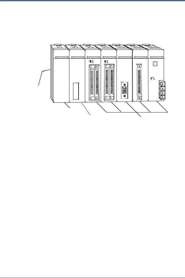
A2.2.1 Components
„Module Names
Base module
Power supply module 
CPU module 
I/O modules and special modules
FA020201.VSD
Figure A2.1 FA-M3 Controller
IM 34M6C11-01E 6th Edition : May 10, 2001-00

A2-3
„ FA-M3 Components
z Base Modules
|
Module Description |
Model |
|
Specifications |
|
|
|
|
|
|
|
F3BU04-0N |
Slot for F3PU10/16 power supply module plus 4 |
|
|
|
slots |
(for CPU and I/O modules) |
|
|
|
|
||
|
|
F3BU06-0N |
Slot for F3PU10/16 power supply module plus 6 |
|
|
|
slots |
(for CPU and I/O modules) |
|
|
|
|
||
|
Base module |
F3BU09-0N |
Slot for F3PU20/26 power supply module plus 9 |
|
|
slots |
(for CPU and I/O modules) |
||
|
|
|
||
|
|
F3BU13-0N |
Slot for F3PU20/26 power supply module plus 13 |
|
|
|
slots |
(for CPU and I/O modules) |
|
|
|
|
||
|
|
F3BU16-0N |
Slot for F3PU20/26 power supply module plus 16 |
|
|
|
slots |
(for CPU and I/O modules) |
|
|
|
|
||
z Power Supply Modules |
|
|
||
Module Description |
Model |
Specifications |
|
|
|
|
|
|
F3PU10-0N |
100 to 240 V AC, for F3BU04 and F3BU06 |
|
|
|
|
NEW |
Power supply module |
F3PU16-0N |
24 V DC, for F3BU04 and F3BU06 |
|
|
|
|
|
F3PU20-0N |
100-240 V AC, for F3BU09, F3BU13 and F3BU16 |
|
|
|
|
||
|
|
|
|
|
F3PU26-0N |
24 V DC, for F3BU09, F3BU13 and F3BU16 |
|
|
|
|
|
z CPU Modules
Module Description |
Model |
Specifications |
|
|
|
|
|
|
|
|
F3SP21-0N |
10K ladder steps, with 0.18 to 0.36 s execution |
|
|
|
time for basic instructions |
|
||
|
|
|
||
|
F3SP25-2N |
20K ladder steps, with 0.12 to 0.24 s execution |
|
|
|
time for basic instructions |
|
||
|
|
|
||
|
F3SP35-5N |
100K ladder steps, with 0.09 to 0.18 s execution |
|
|
|
time for basic instructions |
|
||
|
|
|
||
|
F3SP28-3N |
30K ladder steps, with 0.045 to 0.18 s execution |
NEW |
|
Sequence CPU module |
time for basic instructions |
|||
|
|
|||
(with memory) |
F3SP38-6N |
120K ladder steps, with 0.045 to 0.18 s |
NEW |
|
|
execution time for basic instructions |
|||
|
|
|
||
|
F3SP53-4H |
56K ladder steps, with 0.0175 to 0.07 s |
NEW |
|
|
execution time for basic instructions |
|||
|
|
|
||
|
F3SP58-6H |
120K ladder steps, with 0.0175 to 0.07 s |
NEW |
|
|
|
execution time for basic instructions |
|
|
|
F3FP36-3N |
For SFC/ladder language; 40K ladder steps |
|
|
|
Contact coil 0.09 s per instruction |
|
||
|
|
|
||
BASIC CPU module |
F3BP20-0N |
120 KB for BASIC |
|
|
|
|
|
||
F3BP30-0N |
510 KB for BASIC |
|
||
|
|
|||
|
|
|
|
z ROM Packs
Module Description |
Model |
Specifications |
|
|
|
|
|
|
|
|
RK10-0N |
5K ladder steps (F3SP21/30) |
|
|
|
|
|
|
|
|
RK30-0N |
20K ladder steps; 120KB for BASIC |
|
|
|
(F3SP21/25/30/35, F3BP20) |
|
||
|
|
|
||
|
RK50-0N |
100K ladder steps; 510KB for BASIC |
|
|
ROM pack |
(F3SP21/25/35, F3BP30) |
|
||
|
|
|||
RK33-0N |
56K ladder steps (F3SP21/25/28/35/38/53/58) |
NEW |
||
|
||||
|
|
|
|
|
|
RK53-0N |
100K ladder steps; 510KB for BASIC |
NEW |
|
|
F3SP21/25/35, F3BP30) |
|||
|
|
|
||
|
RK73-0N |
120K ladder steps, (F3SP28/38/53/58) |
NEW |
|
|
|
|
|
IM 34M6C11-01E 6th Edition : May 10, 2001-00

A2-4
z I/O Modules
Module Description |
Model |
|
Specifications |
|
|
|
|
|
|
High-speed input module |
F3XH04-3N |
24 V DC high-speed input points with pulse-capture feature, 4 points |
|
|
|
|
|
|
|
AC input module |
F3XA08-1N |
100 to 120 V AC, 8 points |
|
|
|
|
|
|
|
F3XA08-2N |
200 to 240 V AC, 8 points |
|
||
|
|
|||
|
|
|
|
|
|
F3XD08-6F |
DC Input sink/source, 12 to 24 V DC, 8 points *1 |
NEW |
|
|
|
|
|
|
|
F3XD16-3F |
DC Input sink/source, 24 V DC, 16 points *1 |
NEW |
|
|
|
|
|
|
|
F3XD16-4F |
DC Input sink/source, 12 V DC, 16 points *1 |
NEW |
|
|
F3XD16-3H |
DC Input sink (positive common), 24 V DC, 16 points |
NEW |
|
|
(High speed input) |
|||
|
|
|
||
|
F3XD32-3F |
DC Input sink/source, 24 V DC, 32 points *1 |
NEW |
|
|
|
|
|
|
|
F3XD32-4F |
DC Input sink/source, 12 V DC, 32 points *1 |
NEW |
|
|
F3XD32-5F |
DC Input sink/source, 5 V DC, 32 points *1 |
NEW |
|
|
|
|
|
|
|
F3XD64-3F |
DC Input sink/source, 24 V DC, 64 points *1 |
NEW |
|
|
|
|
|
|
DC input module |
F3XD64-4F |
DC Input sink/source, 12 V DC, 64 points *1 |
NEW |
|
|
F3XD08-6N |
DC input sink/ source, 12 to 24 V DC, 8 points |
|
|
|
|
|
|
|
|
F3XD16-3N |
DC Input sink/source, 24 V DC, 16 points |
|
|
|
|
|
|
|
|
F3XD16-4N |
DC Input sink/source, 12 V DC, 16 points |
|
|
|
|
|
|
|
|
F3XD32-3N |
DC Input sink/source, 24 V DC, 32 points |
|
|
|
|
|
|
|
|
F3XD32-4N |
DC Input sink/source, 12 V DC, 32 points |
|
|
|
|
|
|
|
|
F3XD32-5N |
DC Input sink/source, 5 V DC, 32 points |
|
|
|
|
|
|
|
|
F3XD64-3N |
DC Input sink/source, 24 V DC, 64 points |
|
|
|
|
|
|
|
|
F3XD64-4N |
DC Input sink/source, 12 V DC, 64 points |
|
|
|
|
|
|
|
|
F3XD64-6M |
DC Input matrix scan, 12 to 24 V DC, 64 points |
|
|
|
|
|
|
|
Voltage-free contact input |
F3XC08-0N |
No-voltage contact input, 8 points |
|
|
module |
|
|||
|
|
|
|
|
Triac output module |
F3YA08-2N |
Triac output |
(100 to 240 V AC), 2 A, 8 points |
|
|
|
|
|
|
|
F3YC08-0C |
Relay output |
(24 V DC, 100 to 240 V AC), 2 A, 8 points, all |
NEW |
|
independent |
|
||
Relay output module |
|
|
|
|
F3YC08-0N |
Relay output |
(24 V DC, 100 to 240 V AC), 2 A, 8 points |
|
|
|
|
|
|
|
|
F3YC16-0N |
Relay output (24 V DC, 100 to 240 V AC), 2 A, 16 points |
|
|
|
|
|
|
|
|
F3YD04-7N |
TR output, 24 V DC, 2 A, all independent, 4 points |
|
|
|
|
|
|
|
|
F3YD08-6A |
TR output sink type, 12 to 24 V DC, 1 A, 8 points |
|
|
|
|
|
|
|
|
F3YD08-6B |
TR output source type, 12 to 24 V DC, 1 A, 8 points |
|
|
|
|
|
|
|
|
F3YD14-5A |
TR output sink type, 12 to 24 V DC, 0.5 A, 14 points |
|
|
|
|
|
|
|
|
F3YD14-5B |
TR output source type, 12 to 24 V DC, 0.5 A, 14 points |
|
|
Transistor output module |
|
|
|
|
F3YD32-1A |
TR output sink type, 12 to 24 V DC, 0.1 A, 32 points |
|
||
|
|
|
|
|
|
F3YD32-1B |
TR output souece type, 12 to 24 V DC, 0.1 A, 32 points |
|
|
|
|
|
|
|
|
F3YD32-1T |
TTL output, 5 V DC, 16 mA, 32 points |
|
|
|
|
|
|
|
|
F3YD64-1F |
TR output sink type, 24 V DC, 0.1 A, 64 points *2 |
NEW |
|
|
|
|
|
|
|
F3YD64-1A |
TR output sink type, 24 V DC, 0.1 A, 64 points |
|
|
|
|
|
|
|
|
F3YD64-1M |
TR output matrix scan, 12 to 24 V DC, 0.1 A, 64 points ( 8 x 8 ) |
|
|
|
|
|
|
|
|
F3WD64-3F |
DC Input sink/source, 24 V DC, 32 points *1 |
NEW |
|
|
TR Output sink type, 24 V DC, 0.1 A, 32 points *2 |
|||
|
F3WD64-4F |
DC Input sink/source, 12 V DC, 32 points *1 |
NEW |
|
I/O module |
TR Output sink type, 12 V DC, 0.1 A, 32 points *2 |
|||
F3WD64-3N |
DC Input sink/source, 24 V DC, 32 points |
|
||
|
|
|||
|
|
TR Output sink type, 24 V DC, 0.1 A, 32 points |
|
|
|
F3WD64-4N |
DC Input sink/source, 12 V DC, 32 points *1 |
|
|
|
|
TR Output sink type, 12 V DC, 0.1 A, 32 points |
|
|
*1: Input response of 100 s or more can be set when F3SP28, F3SP38, F3SP53 or F3SP58 module is used.
*2: The output HOLD/RESET for a fatal failure of a CPU can be set when F3SP28, F3SP38, F3SP53 or F3SP58 module is used.
IM 34M6C11-01E 6th Edition : May 10, 2001-00

A2-5
z Analog I/O and Temperature Control Modules
Module Description |
Model |
Specifications |
|
|
|
|
|
Analog input module |
F3AD04-0N |
0 to 5/1 to 5/-10 to 10 V DC input, 4 points |
|
|
|
||
F3AD08-1N |
0 to 5/1 to 5/-10 to 10 V DC input, 8 points |
||
|
|||
|
|
|
|
|
F3DA02-0N |
–10 to 10 V/4 to 20 mA DC output, 2 points |
|
Analog output module |
|
|
|
F3DA04-1N |
–10 to 10 V/4 to 20 mA DC output, 4 points |
||
|
|
|
|
|
F3DA08-5N |
–10 to 10 V DC output, 8 points |
|
|
|
|
|
|
F3CT04-0N |
Thermocouple or mV input, 0.5 second scan, 4 |
|
|
loops |
||
|
|
||
Temperature |
F3CT04-1N |
Thermocouple or mV input, 0.5 second scan, 4 to |
|
20 mA DC output, 4 loops |
|||
|
|||
control/monitoring module |
|
|
|
F3CR04-0N |
RTD input, 0.5 second scan, 4 loops |
||
|
|||
|
|
|
|
|
F3CR04-1N |
RTD input, 0.5 second scan, 4 to 20 mA DC |
|
|
output, 4 loops |
||
|
|
||
PID control module |
F3CV04-1N |
DC-voltage input, 0.5 second scan, 4 loops |
|
|
|
|
z Communication Modules
Module Description |
Model |
|
Specifications |
|
|
|
|
|
|
|
F3LC11-1F |
1 |
RS-232-C port; 115.2 kbps max. |
|
|
|
|
|
|
Personal computer link |
F3LC11-1N |
1 |
RS-232C port; 19200 bps max. |
|
|
|
|
||
module |
F3LC11-2N |
1 |
RS-422-A/RS-485 port; 19200 bps max. |
|
|
||||
|
|
|
|
|
|
F3LC12-1F |
2 |
RS-232-C ports; 115.2 kbps max. |
|
|
|
|
|
|
UT link module |
F3LC51-2N |
1 |
RS-422-A/RS-485 port of 38400bps max. for |
|
easy connection with a temperature controller |
||||
|
|
|||
DeviceNet interface module |
F3LD01-0N |
1 |
DeviceNet port of 500 kpps max., with |
|
master/scanner functions |
||||
|
|
|||
Ethernet interface module |
F3LE01-5T |
10Mbps, 10BASE5/10BASE-T |
||
RS-232-C communication |
F3RS22-0N |
2 |
RS-232-C ports; 19200 bps max. |
|
module |
||||
|
|
|
||
RS-422 communication |
F3RS41-0N |
1 |
RS-422-A/RS-485 port; 19200 bps max. |
|
module |
||||
|
|
|
||
Ladder communication |
F3RZ81-0N |
1 |
RS-232-C port; 19200 bps max. |
|
|
|
|
||
module |
F3RZ91-0N |
1 |
RS-422/RS-485 port; 19200 bps max. |
|
|
||||
|
|
|
|
|
GP-IB communication |
F3GB01-0N |
1 |
GP-IB communication port |
|
module |
||||
|
|
|
||
z FA Link and Fiber-optic FA-bus Modules
Module Description |
Model |
Specifications |
|
|
|
|
|
FA link H module |
F3LP02-0N |
Up to 32 stations with a transmission distance |
|
of 1 km max., 1.25 Mbps |
|||
|
|
||
Fiber-optic FA link H module |
F3LP12-0N |
Up to 32 stations with an extensive distance |
|
of 10 km max., 1.25 Mbps |
|||
|
|
||
Fiber-optic FA-bus module |
F3LR01-0N |
Up to 6 stations with a base-to-base distance |
|
of 200 m max., 10 Mbps |
|||
|
|
||
Fiber-optic FA-bus 2 module |
F3LR02-0N |
Up to 32 stations with an extensive distance |
|
of 1.4 km max., 10 Mbps |
|||
|
|
NEW
NEW
IM 34M6C11-01E 6th Edition : May 10, 2001-00

A2-6
z Counter and Positioning Modules
Module Description |
Model |
Specifications |
|
|
|
|
|
High-speed counter module |
F3XP01-0H |
100 kpps, 1 channel, 32 bits |
|
|
|
||
F3XP02-0H |
100 kpps, 2 channels, 32 bits |
||
|
|||
|
|
|
|
Pulse input module |
F3XS04-3N |
20 kHz, 4 channels, 24 V input, 16 bits |
|
|
|
||
F3XS04-4N |
20 kHz, 4 channels, 12 V input, 16 bits |
||
|
|||
|
|
|
|
Positioning module |
F3NC11-0N |
1-axis position and speed control with a max. |
|
speed of 250 kbps |
|||
(Advanced model with |
|
||
|
2-axis position and speed control with a max. |
||
positioning pulse output) |
F3NC12-0N |
||
speed of 250 kbps |
|||
|
|
||
Positioning module |
F3NC51-0N |
1-axis position and speed control with a max. |
|
speed of 2M pps |
|||
(Model with speed-control |
|
||
|
1-axis position and speed control with a max. |
||
voltage output) |
F3NC52-0N |
||
speed of 2M pps |
|||
|
|
||
Positioning module |
F3YP04-0N |
4-axis position control with a max. speed of |
|
250000 pps |
|||
(Model with multichannel |
|
||
|
8-axis position control with a max. speed of |
||
pulse output) |
F3YP08-0N |
||
250000 pps |
|||
|
|
IM 34M6C11-01E 6th Edition : May 10, 2001-00

A2-7
z Cables
Cable Description |
Model |
Style |
Specifications |
|
Code |
||||
|
|
|
||
Cable for programming |
KM11-2T |
*A |
*1 |
|
tools |
D-sub, 9-pin, male, 3 m long |
|||
KM11-3T |
*A |
D-sub, 9-pin, male, 5 m long*1 |
||
|
||||
|
|
|
|
|
|
KM11-4T |
*A |
D-sub, 9-pin, male, 10 m long*1 |
|
|
|
|
|
|
CPU port/9-pin D-sub |
KM10-0C |
― |
D-sub, 9-pin, female, approx. 0.5 m long |
|
adapter cable |
||||
|
|
|
||
Fiber-optic cord*3 *4 for |
KM60-S06 |
― |
Cord for system expansion inside panel enclosure; 0.6 m long |
|
wiring inside panel |
|
|
|
|
KM60-001 |
― |
Cord for system expansion inside panel enclosure; 1 m long |
||
enclosure (compatible |
||||
with F3LR01, F3LR02 and |
|
|
|
|
KM60-003 |
― |
Cord for system expansion inside panel enclosure; 3 m long |
||
F3LP12) |
||||
|
|
|
||
Fiber-optic cable*3 *4 for |
KM61-010 |
― |
Cable for indoor system expansion; 10 m long |
|
indoor wiring, supplied |
|
|
|
|
|
|
Cable for indoor system expansion; 100 m long |
||
with tension member |
KM61-100 |
― |
||
(supplied with one pulling eye) |
||||
(compatible with F3LR01, |
|
|
||
|
|
Cable for indoor system expansion; 150 m long |
||
F3LR02 and F3LP12) |
KM61-150 |
― |
||
(supplied with one pulling eye) |
||||
|
|
|
||
|
KM61-200 |
― |
Cable for indoor system expansion; 200 m long |
|
|
(supplied with one pulling eye) |
|||
|
|
|
||
Fiber-optic cable*3 *4 for |
KM62-100 |
― |
Cable for outdoor system expansion; 100 m long |
|
outdoor wiring, supplied |
(supplied with one pulling eye) |
|||
|
|
|||
with tension member |
KM62-200 |
― |
Cable for outdoor system expansion; 200 m long |
|
(compatible with |
(supplied with one pulling eye) |
|||
|
|
|||
F3LR01 [up to 200 m], |
KM62-300 |
― |
Cable for outdoor system expansion; 300 m long |
|
F3LR02 [up to 200 m], |
(supplied with one pulling eye) |
|||
|
|
|||
and |
KM62-400 |
― |
Cable for outdoor system expansion; 400 m long |
|
F3LP12 [up to 1000 m]) |
(supplied with one pulling eye) |
|||
|
|
|||
|
KM62-500 |
― |
Cable for outdoor system expansion; 500 m long |
|
|
(supplied with one pulling eye) |
|||
|
|
|
||
|
KM62-600 |
― |
Cable for outdoor system expansion; 600 m long |
|
|
(supplied with one pulling eye) |
|||
|
|
|
||
|
KM62-700 |
― |
Cable for outdoor system expansion; 700 m long |
|
|
(supplied with one pulling eye) |
|||
|
|
|
||
|
KM62-800 |
― |
Cable for outdoor system expansion; 800 m long |
|
|
(supplied with one pulling eye) |
|||
|
|
|
||
|
KM62-900 |
― |
Cable for outdoor system expansion; 900 m long |
|
|
(supplied with one pulling eye) |
|||
|
|
|
||
|
KM62-L01 |
― |
Cable for outdoor system expansion; 1000 m long |
|
|
(supplied with one pulling eye) |
|||
|
|
|
||
Fiber-optic cable*3 for |
KM67-300 |
― |
Cable for outdoor system expansion; 300 m long |
|
outdoor wiring, supplied |
(supplied with one pulling eye) |
|||
|
|
|||
with tension member |
KM67-400 |
― |
Cable for outdoor system expansion; 400 m long |
|
(compatible with F3LR02 |
(supplied with one pulling eye) |
|||
|
|
|||
(200 to 500 m)) |
KM67-500 |
― |
Cable for outdoor system expansion; 500 m long |
|
|
(supplied with one pulling eye) |
|||
|
|
|
||
Cable for connector |
KM55-005 |
― |
For connection between module and connector terminal block; 0.5 m long |
|
terminal blocks*2 |
|
|
|
|
KM55-010 |
― |
For connection between module and connector terminal block; 1 m long |
||
|
||||
|
|
|
|
|
|
KM55-015 |
― |
For connection between module and connector terminal block; 1.5 m long |
|
|
|
|
|
|
|
KM55-020 |
― |
For connection between module and connector terminal block; 2 m long |
|
|
|
|
|
|
|
KM55-025 |
― |
For connection between module and connector terminal block; 2.5 m long |
|
|
|
|
|
|
|
KM55-030 |
― |
For connection between module and connector terminal block; 3 m long |
|
|
|
|
|
*1 : Supports DOS/V.
*2 : Cannot be used with F3YP04 and F3YP08 since they use 48-pin connectors.
*3 : For details, see “Fiber-optic FA-bus Module and Fiber-optic FA-bus Type 2 Module” Manual (IM34M6H45-01E). *4 : For details, see “FA Link H Module and Fiber-optic FA Link H Module” Manual (IM34M6H43-01E).
IM 34M6C11-01E 6th Edition : May 10, 2001-00

A2-8
z Spare Parts
|
Module Description |
Model |
Specifications |
|
|
|
|
Terminal block unit* |
TA40-0N |
40 points; voltage rating: 5 to 24 V DC |
|
|
|
|
|
|
|
TA50-0N |
Connector terminal block 40 points (M3.5 screw) |
|
|
|
|
Connector terminal block* |
TA50-1N |
Connector terminal block 40 points (M3 screw) |
|
|
|
TA60-0N |
Connector terminal block 40 points (Europe |
|
|
terminal type) |
|
|
|
|
|
Blank module |
F3BL00-0N |
For empty I/O slots |
|
|
|
|
|
* : |
Cannot be used with F3YP04 |
and F3YP08 modules since they use 48-pin connectors |
|
z Accessory
|
Description |
Part |
Applicable Module |
|
|
Number |
|||
|
|
|
||
Terminal for 10-point terminal block |
A1474JT |
F3XH04, F3XA08, F3XD08, |
||
|
|
|
F3YD04, F3YA08, F3YC08-0N, |
|
Terminal cover for 10-point terminal block |
A1472JT |
|||
F3YD08, F3AD04, F3DA02 |
||||
|
|
|
||
Terminal for 18-point terminal block |
A1496JT |
F3XD16, F3YD14, F3YC08-0C, F3YC16, |
||
|
|
|
F3CR04, F3CV04, F3AD08, F3DA04, |
|
Terminal cover for 18-point terminal block |
A1494JT |
|||
F3DA08,F3XS04, F3HB08 |
||||
|
|
|
|
|
Soldered connector (40-pin plug) |
* |
F3XD32, F3XD64, F3WD64, |
||
A1451JD |
F3XP01, F3XP02 |
|||
|
|
|
||
Cover for connector (40-pin plug) |
A1452JD* |
F3YD32, F3YD64, F3NC01, F3NC02 |
||
|
|
|
F3NC11, F3NC12, F3NC51, F3NC52 |
|
Soldered connector (48-pin plug) |
A1612JD* |
F3YP04, F3YP08 |
||
|
|
|
||
Cover for connector (48-pin plug) - 2 units |
A1613JD* |
|||
|
||||
|
|
|
|
|
Dustproof connector cover - 20 units |
T9031AS |
F3BU04, F3BU06, F3BU09, F3BU13, |
||
F3BU16 |
||||
|
|
|
||
Rail-mounting kit |
T9031AP* |
F3BU04, F3BU06 |
||
|
|
|||
T9031AQ* |
F3BU09, F3BU13 |
|||
|
|
|||
* : |
Not supplied with the product |
|
|
|
IM 34M6C11-01E 6th Edition : May 10, 2001-00
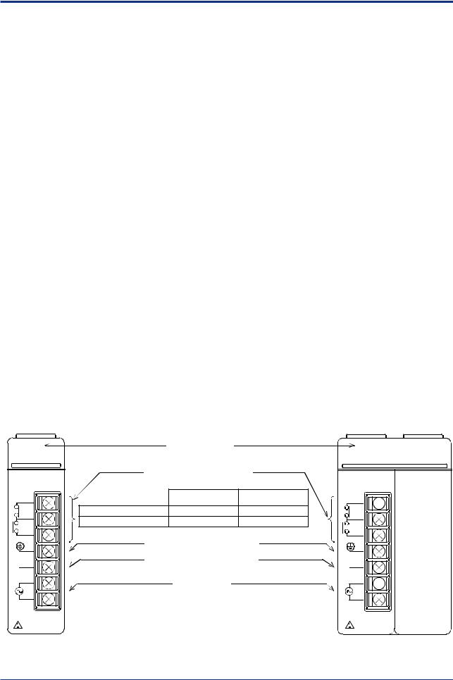
A2-9
A2.3 Power Supply Modules
„ F3PU10-0N/F3PU20-0N Power Supply Modules
z Specifications
|
Item |
|
Specifications |
|||
|
|
|
|
|
|
|
|
|
F3PU10-0N |
|
|
F3PU20-0N |
|
|
|
|
|
|
||
|
|
|
|
|
||
|
Supply voltage range |
|
100 to 240 V AC, single phase 50/60 Hz |
|||
|
|
|
|
|
|
|
|
Range of supply voltage |
|
85 to 264 V AC 50/60 Hz±3 Hz |
|||
|
change |
|
||||
|
|
|
|
|
|
|
|
Power consumption |
|
35VA |
|
|
85VA |
|
|
|
|
|
|
|
|
Inrush current |
|
20 A max. |
(120 V AC, Ta=25°C) |
||
|
|
45 A max. (240 V AC, Ta=25°C) |
||||
|
|
|
||||
|
|
|
1 A time-lag fuse |
|
|
2 A time-lag fuse |
|
Fuse |
|
(Built into the L and N terminals |
|
(Built into the L and N terminals and |
|
|
|
|
and cannot be replaced.) |
|
|
cannot be replaced.) |
|
Rated output voltage |
|
|
5 V DC |
||
|
|
|
|
|
|
|
|
Rated output current |
|
2.0 A |
|
|
4.3 A |
|
|
|
|
|
||
|
Insulation resistance |
|
5 M Ω min. when tested between a group of external AC terminals and |
|||
|
|
the FG terminal using a 500 VDC insulation resistance tester |
||||
|
|
|
||||
|
Withstanding voltage |
|
1500 V AC for one minute |
|||
|
|
between a group of external AC terminals and the FG terminal |
||||
|
|
|
||||
|
Leakage current |
|
|
3.5 mA max |
||
|
|
|
|
|
|
|
|
Allowable momentary power |
|
|
20 ms |
||
|
failure time |
|
|
|
||
|
|
|
|
|
|
|
|
External dimensions |
|
28.9 (W) × 100 (H) × 83.2 (D) mm* |
|
58 (W) × 100 (H) × 83.2 (D) mm * |
|
|
|
|
|
|
|
|
|
Weight |
|
190 gf |
|
|
320 gf |
|
|
|
|
|
|
|
|
Applicable base module |
|
Dedicated to |
|
|
Dedicated to |
|
|
F3BU04 and F3BU06 |
|
|
F3BU09, F3BU13 and F3BU16 |
|
|
|
|
|
|
||
*: |
Excluding protrusions |
(see the dimensional figures for more information) |
||||
|
z Components and Their Functions |
|
|
|||
|
The figure below shows the power supply modules with their covers removed. |
|
||||
F3PU10-0N |
|
|
|
F3PU20-0N |
|
|
|
RDY indicator (green) |
|
Lit when the power |
|
|
|
RDY |
|
supply module is |
|
RDY |
|
|
|
|
|
|
|||
|
|
|
normal. |
|
|
|
PU 10-0N |
POWER |
FAIL signal contact output |
|
PU 20-0N |
POWER |
|
|
|
Contact ratings: 24V DC, 0.3A |
|
|
||
FAIL |
|
|
Normal operating |
System Failure and |
FAIL |
|
OUTPUT |
|
|
OUTPUT |
|
||
FAIL1 |
|
|
time |
Power Failure Times |
FAIL1 |
|
COM |
Across FAIL1 and COM |
Open |
Short |
COM |
|
|
Across FAIL2 and COM |
Short |
Open |
|
|||
|
|
|
||||
FAIL2 |
FG |
Subject to JIS class 3 grounding |
FAIL2 |
|
||
|
|
|
||||
FG |
LG |
|
independently |
|
FG |
|
|
Connect to FG and grounded |
|
|
|||
LG |
|
LG |
|
|||
|
|
|
|
|
||
N |
Power supply |
|
100 to 240V AC |
|
N |
|
|
|
|
|
|
|
|
L |
|
|
|
|
L |
|
INPUT |
|
|
|
|
INPUT |
|
100-240VAC ` |
|
|
|
100-240VAC ` |
|
|
|
|
|
|
|
|
FA020303.VSD |
Figure A2.2 F3PU10-0N and F3PU20-0N Power Supply Modules
IM 34M6C11-01E 6th Edition : May 10, 2001-00
Loading...