


DL7100

Service
Manual
Yokogawa Electric Corporation
SM 701410-01E
SM 701410-01E
3rd Edition
Model 7014
DL7100/DL7200
Digital Oscilloscope

SM 701410-01E
1
IMPORT ANT NOTICE TO THE USER
This manual contains information for servicing YOKOGAWA’s DL7100/DL7200 Series
Digital Oscilloscopes. Check the serial number to confirm that this is the correct
service manual for the instrument to be serviced. Do not use the wrong manual.
Before any maintenance and servicing, read all safety precautions carefully .
Only properly trained personnel may carry out maintenance and servicing described
in this service manual.
Do not disassemble the instrument or its parts, unless otherwise clearly permitted by
this service manual.
Do not replace any part or assembly, unless otherwise clearly permitted by this
service manual.
In principle, Yokogawa Electric Corporation (YOKOGAWA) does not supply parts
other than those listed in the customer maintenance parts list in this service manual
(mainly modules and assemblies). Therefore if an assembly fails, the user should
replace the whole assembly and not components within the assembly (see “Note”). If
the user attempts to repair the instrument by replacing individual components within the
assembly, YOKOGAWA assumes no responsibility for any consequences such as
defects in instrument accuracy, functionality, reliability, or user safety hazards.
YOKOGAWA does not offer more detailed maintenance and service information than
that contained in this service manual.
All reasonable efforts have been made to assure the accuracy of the content of this
service manual. However, there may still be errors such as clerical errors or omissions.
YOKOGAWA assumes no responsibility of any kind concerning the accuracy or
contents of this service manual, nor for the consequences of any errors.
All rights reserved. No part of this service manual may be reproduced in any form or by
any means without the express written prior permission of YOKOGAWA. The contents
of this manual are subject to change without notice.
Disk No. SM12
3rd Edition : March 2002 (YK)
All Rights Reserved, Copyright © 1999, Yokogawa Electric Corporation

SM 701410-01E
2
NOTE YOKOGAWA instruments have been designed in a way that the replacement of elec-
tronic parts can be done on an assembly (module) basis by the user. YOKOGAWA
instruments have also been designed in a way that troubleshooting and replacement of
any faulty assembly can be done easily and quickly. Therefore, YOKOGAWA strongly
recommends replacing the entire assembly over replacing parts or components within
the assembly. The reasons are as follows:
• The instruments use high-performance microprocessors, large scale CMOS gate arrays,
and surface-mount components to provide state-of-the-art performance and functions.
• Repair of components can only be performed by specially trained and qualified mainte-
nance personnel with special highly-accurate tools, including costly ones.
•When taking the service life and cost of the instruments into consideration, the replace-
ment of assemblies offers the user the possibility to use YOKOGAWA instruments more
effectively and economically with a minimum in downtime.
Adobe and Acrobat are trademarks of Adobe system incorporated.
INTRODUCTION
This manual contains information for servicing YOKOGAWA DL7100/DL7200 Series
Digital Oscilloscopes.
NOTE This manual is the third edition, March 2002.
WARNING
This service manual is to be used by properly trained personnel only. To avoid
personal injury, do not perform any servicing unless you are qualified to do so.
Refer to the safety precautions prior to performing any servicing.
Even if servicing is carried out according to this service manual, or by qualified
personnel, YOKOGAWA assumes no responsibility for any result occurring from
that servicing.
SAFETY PRECAUTIONS
The following general safety precautions must be observed during all phases of opera-
tion, service, and repair of this instrument. Failure to comply with these precautions or
with specific warnings given elsewhere in this manual violates safety standards of
design, manufacture, and intended use of the instrument.
[Yokogawa Electric Corporation] assumes no liability for the customer’s failure to
comply with these requirements.
SM 701410-01E
3
General definitions of safety symbols used on equipment and in manuals
Explanation: To avoid injury, death of personnel or damage to the instrument, the
operator must refer to an explanation in the instruction manual.
This symbol represents a functional grounding terminal. Such terminals should not be
used as a “protective grounding terminal”.
WARNING
A WARNING sign denotes a hazard. It calls attention to a procedure, practice,
condition or the like, which, if not correctly performed or adhered to, could result
in injury or death of personnel.
CAUTION
A CAUTION sign denotes a hazard. It calls attention to a procedure, practice,
condition or the like, which, if not correctly performed or adhered to, could result
in damage to or destruction of part of the product.
WARNING
Power Supply
Ensure the source voltage matches the voltage of the power supply before
turning ON the power.
Power Cord and Plug
To prevent an electric shock or fire, be sure to use the power supply cord
supplied by YOKOGAWA. The main power plug must be plugged in an outlet
with a protective grounding terminal. Do not invalidate protection by using an
extension cord without protective grounding.
Protective Grounding
The protective grounding terminal must be connected to ground to prevent an
electric shock before turning ON the power.
Necessity of Protective Grounding
Never cut off the internal or external protective grounding wire or disconnect the
wiring of the protective grounding terminal. Doing so poses a potential shock
hazard.
Defects in Protective Grounding or Fuses
Do not operate the instrument if you suspect the protective grounding or a fuse
might be defective.
Fuse
To prevent a fire, make sure to use fuses with the specified standard (current,
voltage, type). Before replacing the fuses, turn OFF the power and disconnect
the power source. Do not use a different fuse or short-circuit the fuse holder.

SM 701410-01E
4
Do Not Operate Near Flammable Materials
Do not operate the instrument in the presence of flammable liquids or vapors.
Operation of any electrical instrument in such an environment constitutes a
safety hazard.
Do Not Remove Any Covers
Some areas inside the instrument carry high voltage. Do not remove any cover,
especially if the power supply is connected. The cover should be removed by
qualified personnel only.
External Connection
To ground safely, connect the protective grounding before connecting the
instrument to a measurement or control unit.
HOW TO USE THIS MANUAL
This manual is meant to be used by qualified personnel only. Make sure to read the
safety precautions at the beginning of this manual as well as the warnings and cautions
contained in the chapters relevant to any servicing you may be carrying out.
This manual contains the following chapters:
1 GENERAL INFORMATION
Provides an introduction, and describes safety considerations.
2 PERFORMANCE TEST
Describes the tests for checking the performance of the instrument.
3 ADJUSTMENTS
Describes the adjustments which can be performed by users.
4 PRINCIPLES OF OPERATION
Provides function block diagrams and describes the principles of operation.
5 TROUBLESHOOTING
Describes procedures for troubleshooting and how to proceed in case parts need to be
replaced.
6 SCHEMATIC DIAGRAM
Provides a system configuration diagram.
7 CUSTOMER MAINTENANCE PARTS LIST
Contains exploded views and a list of replaceable parts.
Specifications are not included in this manual; for specifications, refer to IM 701410-
01E.

SM 701410-01E
5
1
2
3
4
5
7
6
CONTENTS
IMPORTANT NOTICE TO THE USER .................................................................................... 1
INTRODUCTION ....................................................................................................................3
SAFETY PRECAUTIONS........................................................................................................3
HOW TO USE THIS MANUAL .................................................................................................4
Chapter 1 GENERAL INFORMATION
1.1 Introduction............................................................................................. 1 - 1
1.2 Safety Considerations ............................................................................ 1 - 1
Chapter 2 PERFORMANCE TEST
2.1 Introduction............................................................................................. 2 - 1
2.2 Test Environment.................................................................................... 2 - 1
2.3 Equipment Required for Performance Test ............................................ 2 - 1
2.4 Self_Diagnosis ....................................................................................... 2 - 2
2.5 Vertical Axis DC Voltage Accuracy Test.................................................. 2 - 2
2.6 Frequency Response Test...................................................................... 2 - 4
2.7 Time-Base Accuracy Test ....................................................................... 2 - 5
2.8 Trigger Sensitivity Test ........................................................................... 2 - 7
2.9 Trigger Accuracy Test ............................................................................. 2 - 8
2.10 Logic Input Function Test ................................................................... 2 - 10
Chapter 3 ADJUSTMENTS
3.1 Introduction............................................................................................. 3 - 1
3.2 Test Environment.................................................................................... 3 - 1
3.3 Equipment Required............................................................................... 3 - 2
3.4 DC Gain Adjustment on the AD board .................................................... 3 - 2
3.5 Flatness Adjustment on the Analog Board ............................................ 3 - 6
Chapter 4 PRINCIPLES OF OPERATION
4.1 Introduction............................................................................................. 4 - 1
4.2 Function of Each Assembly.................................................................... 4 - 1
4.3 Function of Each ASIC ........................................................................... 4 - 5
Chapter 5 TROUBLESHOOTING
5.1 Introduction............................................................................................. 5 - 1
5.2 Flowchart................................................................................................ 5 - 1
5.3 Power Supply Secondary Voltage.......................................................... 5 - 5
5.4 Self Test.................................................................................................. 5 - 6
5.4.1 Key Board Test ........................................................................................................ 5 - 7
5.4.2 Memory Test .............................................................................................................. 5 - 7
5.4.3 FDD Test ................................................................................................................... 5 - 8
5.4.4 SCSI Test .................................................................................................................. 5 - 8
5.4.5 Printer Test ................................................................................................................ 5 - 9
5.4.6 Accuracy Test.......................................................................................................... 5 - 10
5.4.7 PC Card Test (Option)............................................................................................. 5 - 10
Chapter 6 SCHEMATIC DIAGRAM
Chapter 7 CUSTOMER MAINTENANCE PARTS LIST
7.1 Customer Maintenance Parts List .......................................................... 7 - 1
7.2 Standard Accessories............................................................................. 7 - 4

1
GENERAL INFORMATION
1 - 1
SM 701410-01E
1.1 Introduction
Chapter 1 GENERAL INFORMATION
This chapter provides the general information.
1.1 Introduction
1.2 Safety Considerations
1.1 Introduction
This manual describes servicing information on any YOKOGAWA DL7100/DL7200
Series Digital Oscilloscopes.
This chapter contains information required for using this manual and information that
must be read before starting servicing of DL7100/DL7200 series instruments.
1.2 Safety Considerations
You must thoroughly read the safety precautions at the beginning of this manual. Also
fully read the warnings and cautions contained in each chapter.

SM 701410-01E
2 - 1
PERFORMANCE TEST
2
2.1 Introduction
Chapter 2 PERFORMANCE TEST
Contents of This Chapter
2.1 Introduction
2.2 Test Environment
2.3 Equipment Required
2.4 Self-Diagnosis
2.5 Vertical Axis DC Voltage Accuracy Test
2.6 Frequency Response Test
2.7 Time-Base Accuracy Test
2.8 Trigger Sensitivity Test
2.9 Trigger Accuracy Test
2.10 Logic Input Function Test
2.1 Introduction
The aim of the test is to check the basic performance of the instrument. The order of the
test procedures is just for convenience and does not have any significant meaning.
Please use recommended equipment or their equivalents.
2.2 Test Environment
1) Operate the instrument under the following conditions.
• Ambient temperature: 23 ±2 °C
• Humidity: 55 ±10% RH
•Voltage of power supply: Specified voltage ±1%
• Frequency of power supply: Specified frequency ±1%
2) Warm up time
•More than 30 minutes after turning ON the instrument.
• Confirm that self-calibration is correctly executed after the 30 minute warm up.
(Be sure to Pay attention to the warm up time of all equipment that will be used in the
test.)
2.3 Equipment Required for Performance Test
Equipment Qty Mandatory Specifications Recommended
Calibrator 1 Accuracy ±0.05% WAVETEK 9500
Output voltage –40 V to 40 V
Output resolution 1 mV
Output frequency range 0.1 MHz to 500 MHz
Programmable head 1 WAVETEK 9520
SM 701410-01E2 - 2
2.4 Self_Diagnosis
Equipment Required
None
Procedure
Follow the procedure described in section 14.3, “Self-Diagnosis Test (Self-Test)” of the
instruction manual (IM 701410-01E) .
2.5 Vertical Axis DC Voltage Accuracy Test
Specifications
2 mV/div to 50 mV/div: ±(1.5% of 8 div.+0.2 mV)
100 mV/div to 500 mV/div: ±(1.5% of 8 div.+2 mV)
1 V/div to 10 V/div: ±(1.5% of 8 div.+20 mV)
Permissible Range
Range Tolerance
2 mV/div ±0.44 mV
5 mV/div ±0.8 mV
10 mV/div ±1.4 mV
20 mV/div ±2.6 mV
50 mV/div ±6.2 mV
100 mV/div ±14 mV
200 mV/div ±26 mV
500 mV/div ±62 mV
1 V/div ±140 mV
2 V/div ±260 mV
5 V/div ±620 mV
10 V/div ±1.22 V
Equipment Required
Equipment Qty Mandatory Specifications Recommended
Calibrator 1 Accuracy ±0.05% WAVETEK 9500
Output voltage –40 V to 40 V
Output resolution 1 mV
Programmable Head 1 WAVETEK 9520
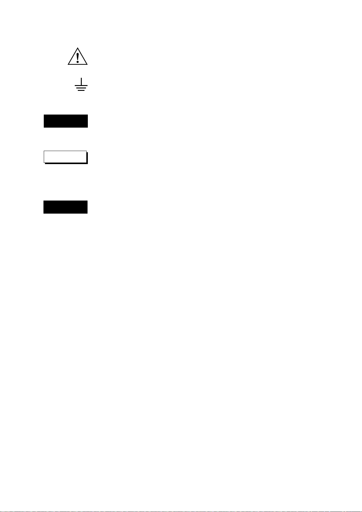
Connection
Calibrator
Programable Head
DL7100/DL7200

SM 701410-01E
2 - 3
PERFORMANCE TEST
2
2.4 Self diagnosis
Procedure
1) Turn on the power source of the DL7100/DL7200. After warm-up press the MISC key,
followed by Calibration soft key, then press the Cal Exec soft key to calibrate the
instrument.
Next, press the INITIALIZE key, then press the Initialize soft key to initialize the
settings.
2) Set the DL7100/DL7200 oscilloscope as shown below.
VERTICAL (for all channels)
Coupling DC1 MΩ
V/div According to the inspection item below
Probe 1:1
HORIZONTAL
T/div 1 ms/div
TRIGGER
Mode Auto
ACQ
Mode Box Average
Count Infinite
DISPLAY
Format Single
MEASURE
Mode ON
Item Set Up ▼ (Set to channel to be measured)
Select A vg.
Time Range 1 –5 div
Time Range 2 +5 div
3) Input the following voltages from the voltage generator to the DL7100/DL7200 to be
tested, read the indication on the DL7100/DL7200 (value of Avg), and compare the
reading with the tolerance.
Measurement Range Test input voltage Tolerance
2 mV/div –8, 0, +8 mV ±0.44 mV
5 mV/div –20, 0, +20 mV ±0.8 mV
10 mV/div –40, 0, +40 mV ±1.4 mV
20 mV/div –80, 0, +80 mV ±2.6 mV
50 mV/div –200, 0, +200 mV ±6.2 mV
100 mV/div –400, 0, +400 mV ±14 mV
200 mV/div –800, 0, +800 mV ±26 mV
500 mV/div –2, 0, +2 V ±62 mV
1 V/div –4, 0, +4 V ±140 mV
2 V/div –8, 0, +8 V ±260 mV
5 V/div –20, 0, +20 V ±620 mV
10 V/div –40, 0, +40 V ±1.22 V
4) Test all channels in the same manner.

SM 701410-01E2 - 4
2.6 Frequency Response Test
Specifications
DC50 Ω (1 V/div to 10 mV/div) DC to 500 MHz (–3 dB point)
DC50 Ω (2 mV/div and 5 mV/div) DC to 400 MHz (–3 dB point)
Permissible Range
Range Input Amplitude (p-p) Input Frequency Permissible Range (Sdev)
1 V/div 5 V 500 MHz 1.26 V to 1.98 V
200 mV/div 1.2 V 500 MHz 301 mV to 476 mV
50 mV/div 0.3 V 500 MHz 75.1 mV to 119 mV
5 mV/div 30 mV 400 MHz 7.51 mV to 11.9 mV
2 mV/div 12 mV 400 MHz 3.01 mV to 4.76 mV
Equipment Required
Equipment Qty Mandatory Specifications Recommended
Calibrator 1 Output voltage 0 V to 10 V WAVETEK 9500
Output resolution 1 mV
Output frequency range 0.1 MHz to 500 MHz
Programmable Head 1 WAVETEK 9520
Connection
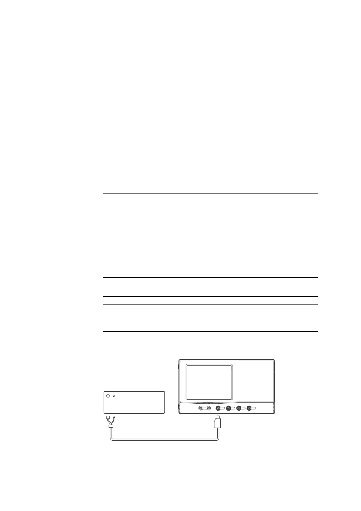
Calibrator
Programable Head
DL7100/DL7200
Procedure
1) Turn on the power source of the DL7100/DL7200. After warm-up press the MISC key,
followed by Calibration soft key, then press the Cal Exec soft key to calibrate the
instrument.
Next, press the INITIALIZE key, then press the Initialize soft key to initialize the
settings.
2) Set the DL7100/DL7200 as shown below.
VERTICAL (for all channel)
Coupling DC50 Ω
V/div Set this according to following measurement
conditions
Probe 1:1
HORIZONTAL
T/div 2 ns/div
TRIGGER SIMPLE
Mode Normal
SIMPLE

SM 701410-01E
2 - 5
PERFORMANCE TEST
2
2.6 Frequency Response Test
Source (Channel to be tested)
ACQ
Mode Average
Count Infinite
Weight 4
Record Length 1 k
DISPLAY
Format Single
MEASURE
Mode ON
Item Set up ▼ (Set to channel to be tested)
Select Sdev
Time Range 1 –5.00 div
Time Range 2 +5.00 div
3) Input voltages as listed on the following table to the DL7100/DL7200 you are testing,
and check if the automatically measured value of waveform parameters (Sdev) is within
the permissible range.
Range Input Amplitude (p-p) Input Frequency Permissible Range (Sdev)
1 V/div 5 V 500 MHz 1.26 V to 1.98 V
200 mV/div 1.2 V 500 MHz 301 mV to 476 mV
50 mV/div 0.3 V 500 MHz 75.1 mV to 119 mV
5 mV/div 30 mV 400 MHz 7.51 mV to 11.9 mV
2 mV/div 12 mV 400 MHz 3.01 mV to 4.76 mV
4) Test all channels in the same manner.
2.7 Time-Base Accuracy Test
Specifications
±0.005%
Permissible Range
Time Range Input Frequency Permissible Range
2 µs/div 500.2 MHz 200±25 kHz
5 µs/div 200.1 MHz 100±10 kHz
Equipment Required
Equipment Qty Mandatory Specifications Recommended
Calibrator 1 300mVp-p, sine wave WAVETEK 9500
200.1MHz and 500.2MHz
Programmable Head 1 WAVETEK 9520
SM 701410-01E2 - 6
Connection
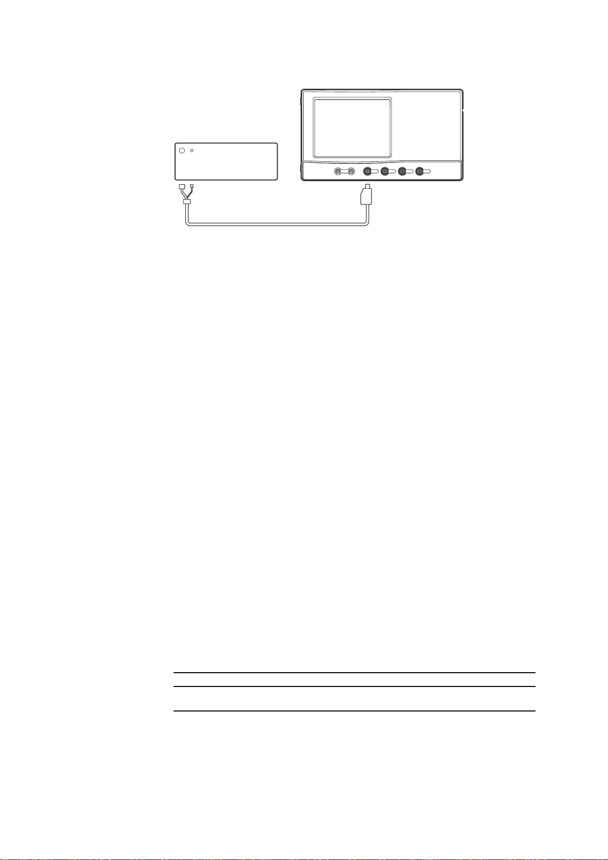
Calibrator
Programable Head
DL7100/DL7200
Procedure
1) Turn on the power source of the DL7100/DL7200. After warm-up press the MISC key,
followed by Calibration soft key, then press the Cal Exec soft key to calibrate the
instrument.
Next, press the INITIALIZE key, then press the Initialize soft key to initialize the
settings.
2) Set the DL7100/DL7200 as shown below.
VERTICAL
CH1
V/div 50 mV/div
Coupling DC50 Ω
Probe 1:1
HORIZONTAL
T/div According to the inspection item below
Display
Format Single
ACQ
Record Length 10k
MEASURE
Mode ON
Item Set up ▼
CH1 Select Freq
3) Input a 300 mVp-p sine wave signal with the input frequency listed in the table below to
the DL7100/DL7200 you are testing, and check if the automatically measured wave-
form parameters (Freq) are within the permissible range.
Time Range Input Frequency Permissible Range (Freq)
2 µs/div 500.2 MHz 200±25 kHz
5 µs/div 200.1 MHz 100±10 kHz
SM 701410-01E
2 - 7
PERFORMANCE TEST
2
2.8 Trigger Sensitivity Test
Specifications
DC to 500 MHz: 1 divp-p on the screen
Permissible Range
500 mV/div 500 MHz 1 divp-p on the screen
Equipment Required
Equipment Qty Mandatory Specifications Recommended
Calibrator 1 500 mVp-p, 500 MHz, sine wave WAVETEK 9500
Programmable Head 1 WAVETEK 9520
Connection
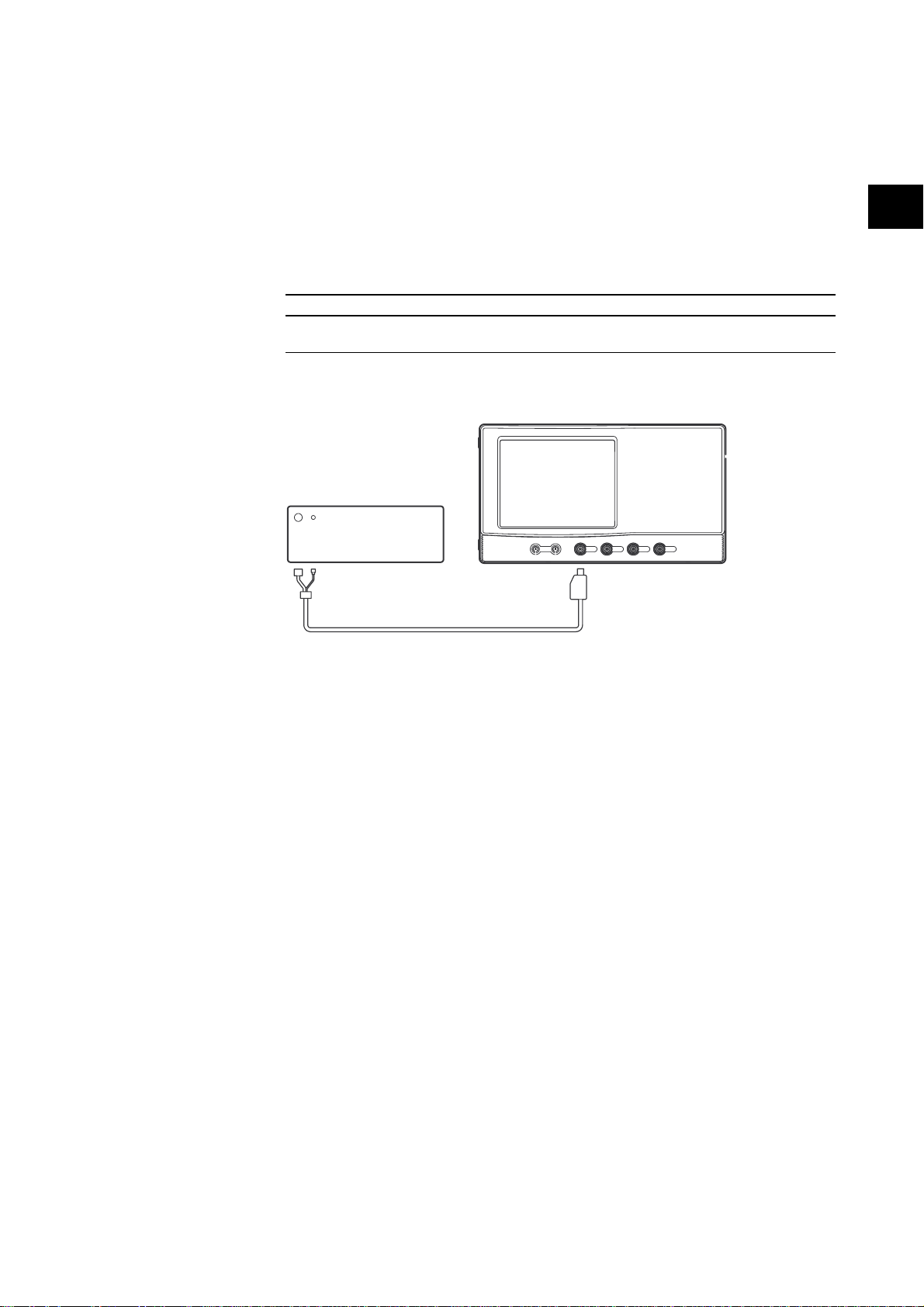
Calibrator
Programable Head
DL7100/DL7200
Procedure
1) Turn on the power source of the DL7100/DL7200. After warm-up press the MISC key,
followed by Calibration soft key, then press the Cal Exec soft key to calibrate the
instrument.
Next, press the INITIALIZE key, then press the Initialize soft key to initialize the
settings.
2) Set the DL7100/DL7200 as shown below.
VERTICAL (for all channels)
V/div 500 mV/div
Coupling DC50 Ω
Probe 1:1
HORIZONTAL
T/div 1ns/div
TRIGGER
Mode Normal
ENHANCED
Type Pattern
Set Pattern ▼
Clock CH (Set to channel to be measured)
Slope ↑ (channel to be measured)
X (the other channel)
2.8 Trigger Sensitivity Test

SM 701410-01E2 - 8
Condition True
Level / Coupling ▼
Level 0 mV
Coupling DC
DISPLAY
Format Single
ACQ
Record Length 1 k
Mode Average
Count Infinite
Weight 4
3) Input a sine wave signal of 500 mVp-p 500 MHz to the DL7100/DL7200, and confirm
that the waveform stabilizes.
NOTE If the trigger is not activated, adjust the trigger lever within ±250 mV until the trigger is
activated.
4) Test all channels in the same manner.
2.9 Trigger Accuracy Test
Specifications
±(1 div.+10% of the trigger level)
Permissible Range (when 200 mV/div)
Trigger level Offset Permissible Range
600 mV 600 mV –260 mV ≤ (Vin + Vout) / 2 ≤ 260 mV
–600 mV –600 mV –260 mV ≤ (Vin + Vout) / 2 ≤ 260 mV
Equipment Required
Equipment Qty Mandatory Specifications Recommended
Calibrator 1 400mVp-p, 2kHz, sine wave WAVETEK 9500
Programmable head 1 WAVETEK 9520
Connection
Calibrator
Programable Head
DL7100/DL7200

SM 701410-01E
2 - 9
PERFORMANCE TEST
2
Procedure
1) Turn on the power source of the DL7100/DL7200. After warm-up press the MISC key,
followed by Calibration soft key, then press the Cal Exec soft key to calibrate the
instrument.
Next, press the INITIALIZE key, then press the Initialize soft key to initialize the
settings.
2) Set the DL7100/DL7200 oscilloscope as follows.
VERTICAL (for all channels)
V/div 200 mV/div
Probe 1:1
Band Width 20 MHz
Offset –600 mV, 600 mV
HORIZONTAL
T/div 100 µs/div
TRIGGER
ENHANCED
Type OR
Window ON
Set Pattern ▼
IN, OUT (channel to be measured)
– (the other channel)
Level / Coupling ▼
Center –600 mV, 600 mV
Width 1.2 V
DISPLAY
Format Single
CURSOR
Type Marker
Position 0.0 div
3) Input a sine wave signal of 400 mVp-p, 2 kHz to the DL7100/DL7200 oscilloscope, and
use cursors to read the voltage of the waveform at the trigger position. Set Vin for
Polarity IN, Vout for Polarity out, and check if (Vin+Vout)/2 is within the permissible
range.
Trigger level Offset Permissible Range
600 mV 600 mV –260 mV ≤ (Vin + Vout) / 2 ≤ 260mV
–600 mV –600 mV –260 mV ≤ (Vin + Vout) / 2 ≤ 260mV
4) Test all channels in the same manner.
2.9 Trigger Accuracy Test
 Loading...