


User’s |
51011, 51012, 51021 |
|
Manual |
Digital Lux Meter |
|
|
|
|
|
|
|
Store this manual in an easily accessible place for quick reference.
IM 51011-01EN
4th Edition: Oct. 2017 (YMI)
Introduction
Thank you for purchasing the digital lux meter.
This user’s manual primarily explains the handling precautions and basic operations of the digital lux meter.
To ensure correct use, please read this manual thoroughly before beginning operation.
After reading this manual, keep it in a safe place.
List of Manuals
The following manuals, including this one, are provided as manuals for the digital lux meter. Please read all manuals.
IM 51011-01E |
User's Manual (this manual) |
IM 51011-93Z2 |
Document for Korea |
Contact information of Yokogawa offices worldwide is provided on
the following sheet. |
|
PIM 113-01Z2 |
Inquiries List of worldwide contacts |
Notes
•The contents of this manual are subject to change without prior notice as a result of continuing improvements to the instrument’s performance and functionality. The figures given in this manual may differ from the actual screen.
•Every effort has been made in the preparation of this manual to ensure the accuracy of its contents. However, should you have any questions or find any errors, please contact your nearest YOKOGAWA dealer.
•Copying or reproducing all or any part of the contents of this manual without the permission of YOKOGAWA is strictly prohibited.
IM 51011-01EN |
1 |
Trademarks
•Adobe, Acrobat, and PostScript are either registered trademarks or trademarks of Adobe Systems Incorporated.
•In this manual, the ® and TM symbols do not accompany their respective registered trademark or trademark names.
•Other company and product names are registered trademarks or trademarks of their respective companies.
Revisions
• February 2013 |
1st Edition |
• October 2013 |
2nd Edition |
• May 2013 |
3rd Edition |
• October 2017 |
4th Edition |
4th Edition: October 2017 (YMI) All Rights Reserved, Copyright ©
2013, Yokogawa Meters & Instruments Corporation,
2017, Yokogawa Test & Measurement Corporation Printed in Japan
2 |
IM 51011-01EN |
Checking the Contents of the Package
Unpack the box and check the contents before operating the instrument. If the wrong items have been delivered, if items are missing, or if there is a problem with the appearance of the items, contact your nearest YOKOGAWA dealer.
Digital Lux Meter
Check that the product that you received is what you ordered by referring to the model name on the name plate.
MODEL |
Specifications |
|
|
51011 |
JIS Class A |
|
Measurement ranges: 99.9/999/9,990/99,900/999,000 |
51012 |
JIS Class AA |
|
Measurement ranges: 99.9/999/9,990/99,900/999,000 |
51021 |
JIS Class AA |
|
Measurement ranges: |
|
9.99/99.9/999/9,990/99,900/999,000 |
|
|
51011, 51012: Single-function model Compliant standard: JIS C 1609-1: 2006
(JIS: Japanese Industrial Standards)
Standard Accessories
AA-size alkaline batteries |
2 |
|
|
|
Recorder output plug (JC017A) |
1 |
|
||
Soft-sided case (RB038A) |
1 |
|
|
|
User’s Manual (Japanese and English) |
2 |
|
||
Optional Accessories (Sold separately) |
|
|
||
|
|
|
|
|
|
Item |
Specifications |
Model |
|
|
|
|
|
|
|
Light-detector extension |
3 m |
|
91001 |
|
cable |
30 m |
|
91002 |
IM 51011-01EN |
3 |

Conventions Used in This Manual
Notes and Cautions
The notes and cautions in this manual are categorized using the following symbols.
Improper handling or use can lead to injury to the user or damage to the instrument.
This symbol appears on the instrument to indicate that the user must refer to
the user's manual for special instructions.
WARNING
Calls attention to actions or conditions that could cause serious or fatal injury to the user, and precautions that can be taken to prevent such occurrences.
CAUTION
Calls attention to actions or conditions that could cause light injury to the user, or cause damage to the instrument or user’s data, and precautions that can be taken to prevent such occurrences.
Note
Calls attention to information that is important for the proper operation of the instrument.
4 |
IM 51011-01EN |

Safety Precautions
This product is designed to be used by a person with specialized knowledge.The general safety precautions described herein must be observed during all phases of operation. If the instrument
is used in a manner not specified in this manual,
the protection provided by the instrument may be impaired. This manual is an essential part of the product; keep it a safe place for future reference.
YOKOGAWA assumes no liability for the customer’s failure to comply with these requirements.
The following symbols are used on this instrument.
Warning: handle with care.
Refer to the user’s manual or service manual. This symbol appears on dangerous locations on
the instrument which require special instructions for proper handling or use.
The same symbol appears in the corresponding place in the manual to identify those instructions.
Make sure to comply with the precautions below. Not complying might result injury or death.
WARNING
Use the instrument Only for Its Intended Purpose
The lux meter is for measuring illuminances. Do not use this meter for any other purpose.
Check the Physical Appearance
Do not use the meter if there is a problem with its physical appearance.
Do Not Disassemble
Only qualified YOKOGAWA personnel may disassemble this product.
Do Not Operate in an Explosive Atmosphere
Do not use this meter in the presence of flammable gases or vapors. Doing so is extremely dangerous.
IM 51011-01EN |
5 |

CAUTION
•The meter is for domestic use (Class B) and meets the electromagnetic compatibility requirements.
•Do not drop the meter or strike it against hard objects.
•Avoid storing the meter in direct sunlight or in a humid environment.
•Using the meter in an low-temperature environment (–10°C to 0°C) may slow down the display’s response.
•Avoid using the meter in a dirty or dusty environment or
in an environment with salt or corrosive gases.
•Do not wipe the meter with organic solvents.
Dirt or dust adhering to the light-detecting surface of the meter decreases measurement accuracy.
Wipe the surface clean with a soft, dry cloth.
•Do not separate the light-detector from the main unit with the power on.
6 |
IM 51011-01EN |

Measurement Category
WARNING
•Do not use the meter for measurements in locations falling that fall under Measurement Categories II, III, and IV.
•Do not use the meter to measure voltage or current.
The meter is designed for measurement category I:
EN 61010-1: 2001
Measurement |
Description |
Remarks |
|
Category |
|||
|
|
||
|
For measurement performed on |
Circuits not connected |
|
CAT I |
circuits not directly connected to |
to a mains power |
|
MAINS. |
|||
|
source. |
||
|
CAT I: EN 61010-1: 2001 |
||
|
|
||
|
|
|
|
CAT II |
For measurement performed on |
Appliances, portable |
|
circuits directly connected to |
equipment, etc. |
||
|
the low-voltage installation. |
||
|
|
||
|
|
|
|
CAT III |
For measurement performed in |
Distribution board, |
|
the building installation. |
circuit breaker, etc. |
||
|
|||
|
|
|
|
|
For measurement performed at |
Overhead wire, |
|
CAT IV |
the source of the low-voltage |
||
cable systems, etc. |
|||
|
installation. |
||
|
|
||
|
|
|
IM 51011-01EN |
7 |
Contents
Introduction . . . . . . . . . . . . . . |
. . |
. |
1 |
|||||
Checking the Contents of the Package . . . |
. . . |
. . |
. . |
. |
. 3 |
|||
Conventions Used in This Manual . . . . . . . . . . |
. . . . . |
. . |
. . . |
. . |
. . |
. . |
. 4 |
|
Safety Precautions . . . . . . . . . . . |
. . . |
. |
. |
. |
5 |
|||
Measurement Category . . . . . . . . . |
. . . |
. |
. |
. |
. |
. |
7 |
|
1. |
Component Names and Functions . . . |
. . . |
. |
. |
. . . . 9 |
|||
2. |
Before Operation . . . . . . . . . . |
. . . |
. |
. |
. |
. |
14 |
|
2.1Measurement Functions . . . . . . . . . . . . . 14
2.2Turning the Power On and Off . . . . . . . . . . . 14
2.3 Setting the Response . . . . . . . . . . . . . . 15
2.4Checking and Replacing Batteries . . . . . . . . . 16
2.5 Automatic Power Off . . . . . . . . . . . . . . . 16
2.6Notes on Illuminance Measurement . . . . . . . . . 18
3. |
Normal Illuminance Measurement . . . . . . |
. |
. . . . . 19 |
4. |
Color Correction Measurement (K Key) . . . . |
|
. . . . . 20 |
5. |
Timer Hold (HOLD and T-H Keys) . . . . . . |
. |
. . . . . 22 |
6. |
Range Hold (RANGE Key) . . . . . . . . . |
|
. . . . . 24 |
7. |
Average Illuminance (AVG Key) . . . . . . . |
|
. . . . . 25 |
8. |
Deviation Display (Δ/% Key) . . . . . . . . |
. |
. . . . . 27 |
9.Light Source Luminous Intensity (cd Key) . . . . . . . . . 28
10.Totalized Intensity of Illumination
(ACC Key) . . . . . . . . . . . . . . |
. . . |
|
|
29 |
11. Comparator (COMP Key) . . . . . . . . |
. . . |
. . |
. |
. 32 |
12.Ripple Measurement (S-F Key) . . . . . . . . . . . . . 33
13.Communication Functions . . . . . . . . . . . . . . . 36
13.1Cable Connection and Interface Specifications . . . . 36
13.2List of Commands . . . . . . . . . . . . . . . . 37
13.3Detailed Description of Commands . . . . . . . . . 38
14.Recorder Output (Analog Output) . . . . . . . . . . . . 41
15. |
Separating the Light Detector . . . |
. . . . . |
. . . . . 42 |
||
16. Supplying Power through USB . . . |
. . . . . |
. . . . . 42 |
|||
17. |
After-Sales Service . . . . . . . |
. . . . . . . . |
. . 43 |
||
|
17.1 |
Error Messages . . . . . . . . . . . . . |
. . . . . . . . . . |
. . . . . . |
. . . . 43 |
|
17.2 |
Calibration . . . . . . . . . |
. . . . . |
. . . |
43 |
18. |
Specifications . . . . . . . . . |
. . . . . |
. . . |
44 |
|
19.Characteristics of Relative Visible-
spectrum Response . . . . . . . . . . . . . . . . . . . . . . . . . . . . . . . . . . 49
20.Characteristic of Oblique Incident Light . . . . . . . . . . 51
21. Illuminance Measurement Method . . . . . . . . . . . 52
22.For the Pollution Control of Electronic
and Electrical Products of the People's Republic of China . . 55
8 |
IM 51011-01EN |
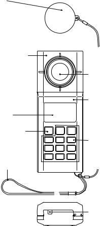
1.Component Names and Functions
Cap
Protects the light-detecting surface Used also during automatic
zero adjustment
Light detector |
|
Can be separated |
|
from the main unit |
Light-detecting surface |
(using an extension |
|
cable) |
|
|
Main unit |
Display |
|
POWER key |
|
Turns the power |
Keys |
on and off |
|
Hand strap |
|
USB port
(mini B type)
Use the USB cable
to communicate to the PC and supply power.
IM 51011-01EN |
9 |
Keys
51021 |
|
|
51011/51012 |
|
||
|
|
|
(single-function model) |
|||
POWER |
RANGE |
CALL |
POWER |
RANGE |
/ % |
|
ON/OFF |
T - H |
ON/OFF |
T - H |
|||
|
|
|||||
/ % |
K |
AVG |
|
|
|
|
1 |
2 |
|
|
|
||
|
|
|
|
|||
COMP |
c d |
ACC |
|
|
|
|
3 |
4 |
C |
|
|
|
|
SET |
S - F |
|
> |
||
|
RANGE Key
Use this key to switch the range.
Press the key to switch to manual range mode.The range changes each time you press the key.To return to auto range mode, hold the key down for at least 1 second.
T-H Key
Use this key to set the timer hold-time or start the timer.
CALL Key
Use this key to view settings.
Values (shown below) that are relevant to the measurement function that you are using are displayed while you hold the key down.
Color correction factor, intensity measurement distance, high and low comparator limits, and ripple ratio
Δ/% Key
Use to display deviation.
Press the key to display the deviation or percentage of measurement data in reference to a reference value. To return to the normal luminance measurement,
hold the key down for at least 1 second.
K Key
Use this key in color correction measurement. Color corrected results are displayed.
A switch is made between normal measurement and color correction measurement each time you press this key. You can also set the color correction factor.
10 |
IM 51011-01EN |

AVG Key
Use this key in average illuminance measurement.
To return to the normal illuminance measurement, hold the key down for at least 1 second.
1, 2, 3, 4, and C Keys
Use this key in average illuminance measurement.
You can store location data for the 4-point method and 5-point method.
(Location number display: 1 2 3 4 C )
COMP Key
Use this key to set the high and low comparator limits and to start the comparator function.
To return to the normal illuminance measurement, hold the key down for at least 1 second.
cd Key
Use this key to set the light intensity distance and to display the intensity.
A switch is made between normal measurement and light source intensity measurement each time you press the key.
ACC Key
Use this key to set the limit for the totalized intensity of illumination and to display the integral time and integral value.
To return to the normal illuminance measurement, hold the key down for at least 1 second.
S-F Key
Use this key in ripple measurement.
A switch is made between normal measurement and ripple measurement each time you press the key.
SET Key
Use this key to configure various settings.
 Key and
  Key
Key
Use these keys to move the setting position and change values.
IM 51011-01EN |
11 |


 Measurement reference
  plane indication
Tripod-mounting screw |
Recorder output |
connector |
|
|
Connect to a |
|
recorder or |
|
oscilloscope with |
|
a dedicated |
|
cable. |
Eject button
Used to separate the light detector from the main unit
Hold switch
Holds the measured data reading
Battery cover |
Response selector |
|
switch |
|
Switches the light |
|
detector response speed |
|
between FAST and SLOW |
12 |
IM 51011-01EN |
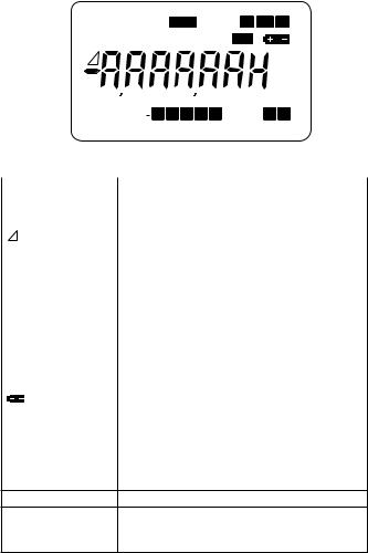
Display
AUTO POWER OFF RCD COMP Lo Go Hi
CALL SET K S-F R-H D-H
 fc S lx h % m


 cdft
cdft
AVG MEMO 1 2 3 4 C RSPS S F
*: When every element is showing (some elements are not used)
|
|
|
|
|
Element |
Description |
|||||||||||||||||
8,8.8.8,8.8.8 |
|
|
|
|
|
|
|
|
|
|
|
Digital display of measured, calculated, and set values |
|||||||||||
AUTO POWER OFF |
Lights in automatic power-off mode |
||||||||||||||||||||||
|
|
|
|
|
|
|
|
|
|
|
|
|
|
|
|
|
|
|
|
|
|
|
Deviation |
CALL |
Lights when CALL is pressed |
||||||||||||||||||||||
SET |
Lights in setting mode |
||||||||||||||||||||||
K |
Color correction factor |
||||||||||||||||||||||
|
|
|
|
|
|
|
|
|
|
|
|
|
|
|
|
|
|
|
|
|
|
|
Lights when a plug is inserted into the recorder output |
|
RCD |
|
|
|
|
|
|
|
|
|
|
|
|
|
|
|
|
|
|
|
|
||
|
|
|
|
|
|
|
|
|
|
|
|
|
|
|
|
|
|
|
|
|
connector |
||
|
|
|
|
|
|
|
|
|
|
|
|
|
|
|
|
|
|
|
|
|
|
|
|
S-F |
Ripple measurement |
||||||||||||||||||||||
|
COMP |
|
|
|
|
|
|
|
|
|
|
|
|
|
|
|
|
|
|
Lights in comparator mode |
|||
|
Lo |
Go |
Hi |
||||||||||||||||||||
|
|
|
|
|
|
|
|
|
|
|
|
|
|
|
|
|
|
|
|
|
|
|
|
R-H |
Lights in range hold mode |
||||||||||||||||||||||
|
|
|
|
|
|
|
|
|
|
|
|
|
|
|
|
Lights in data hold and timer hold modes |
|||||||
|
D-H |
||||||||||||||||||||||
|
|
|
|
|
|
|
|
|
|
|
|
|
|
|
|
|
|
|
|
|
|
|
|
|
|
|
|
|
|
|
|
|
|
|
|
|
|
|
|
|
|
|
|
|
|
|
Lights when the battery voltage is low |
|
AVG-MEMO- |
|
|
|
|
|
|
|
|
|
Lights during average illuminance |
||||||||||||
|
1 |
2 |
3 |
4 |
C |
||||||||||||||||||
|
|
|
|
|
|
|
|
|
|
|
|
|
|
|
|
|
|
|
|
|
|
|
|
RSPS |
|
|
|
|
Response setting |
||||||||||||||||||
S |
F |
||||||||||||||||||||||
|
|
|
|
|
|
|
|
|
|
|
|
|
|
|
|
|
|
|
|
|
|
|
|
S |
Timer hold-time unit (seconds) |
||||||||||||||||||||||
lx |
Unit for illuminance measurement |
||||||||||||||||||||||
h |
Unit for integral time of totalized intensity of illumination |
||||||||||||||||||||||
%Deviation display %
m |
Unit for the distance to the light source |
|
cd |
Unit for luminous intensity; lights during light source |
|
luminous intensity measurement |
||
|
IM 51011-01EN |
13 |

2.Before Operation
2.1Measurement Functions
The meter has the following measurement functions.
51011 |
Single-function model |
|
|
• Normal luminance measurement |
|
51012 |
||
• Deviation display |
||
|
||
|
• Normal luminance measurement |
|
|
• Deviation display |
|
|
• Color correction luminance measurement |
|
51021 |
• Average luminance measurement |
|
• Comparator function |
||
|
||
|
• Light source luminous intensity measurement |
|
|
• Totalized intensity of illumination |
|
|
• Ripple measurement |
|
|
|
Only the color correction function can be used in combination with another function. Operation of other measurement functions are not allowed except for the normal luminance measurement and color correction measurement screens.
2.2 Turning the Power On and Off
CAUTION
Check that the meter operates normally.
14 |
IM 51011-01EN |
Cover the light-detecting surface with the cap, and press the POWER key to turn on the meter.
The initial display appears.
All the LED elements will light, and [--CAL--] will appear
(automatic zero-adjustment mode). Then, the display shows the luminance measurement [0.00 lx] display.
([0.0 lx] appears on Model 51011 and 51012.)
If you press the POWER key again, the meter will turn off.
(See chapter 3, “Normal Illuminance Measurement,” and section 17.1, “Error Messages.”)
2.3 Setting the Response
You can set the response speed of the light detector with the response selector switch.Set the switch to FAST or SLOW according to your application.
Switch |
Response |
Application |
|||
position |
speed |
||||
|
|
|
|||
FAST |
Approx. |
Measurement of continuous light such as |
|||
|
10 ms |
daylight and interior lighting (fluorescent lamps, |
|||
|
|
incandescent lamps). |
|||
|
|
The display shows [RSPS F ]. |
|||
SLOW |
Approx. |
Measurement of the average illuminance of |
|||
|
500 ms |
flickering lights or a light that varies over time |
|||
|
|
such as that from a TV screen. |
|||
|
|
The display shows [RSPS |
S |
]. |
|
|
|
|
|
|
|
Note
If the recorder output is used for waveform observation, set the switch to FAST.
IM 51011-01EN |
15 |
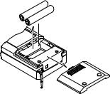
2.4 Checking and Replacing Batteries
When the battery voltage drops, the display area shows a
[  ] mark. When this mark appears, replace the batteries with new ones.
Turn off the power, and remove the battery cover.
Check the polarity markings, and insert the new batteries in the correct orientation. Close the battery cover completely.
Battery type: Two AA dry cells
Battery
Battery cover
Main unit
2.5 Automatic Power Off
The meter has an automatic power-off function to prevent unnecessary battery usage when you forget to turn off the power. If there is no key activity for about 30 minutes, the meter beeps twice and automatically turns off.
Pressing any key while the meter is beeping extends the time until the power turns off for another 30 minutes.
The automatic power-off function is disabled while the totalized intensity of illumination or comparator function is being executed or when a plug is inserted in the recorder output connector. When the automatic power-off function is enabled,
[AUTO POWER OFF] is displayed.
16 |
IM 51011-01EN |
Releasing the Automatic Power-Off Function
Cover the light-detecting surface with the cap.
Press the HOLD switch (HOLD switch lock) and then the POWER key to turn on the power.
After the initial display, [AUTO POWER OFF] disappears and the automatic power-off feature is released.
Press the HOLD switch again to release the HOLD state (lock), and perform measurements.
Reverting the Automatic Power-Off Function
Press the POWER key to turn the power off. Cover the light-detecting surface with the cap. (Check that the HOLD switch is not locked.) Press the POWER key again to turn on the power.
After the initial display, [AUTO POWER OFF] appears, and the automatic power-off function returns.
IM 51011-01EN |
17 |
 Loading...