Yellow Jacket Brute II Operating Manual

YELLOW JACKET®
BRUTE™ II Test & Charging Manifold
OWNER’S MANUAL
Due to the unusually high pressures and hazardous gasses used in refrigeration and air conditioning, only TRAINED refrigeration and air conditioning technicians should use this equipment. Proper procedures must be used.
Section 608 of the Federal Clean Air Act requires that all persons who maintain, service, repair, or dispose of appliances must be certified since November 14, 1994. Failure to comply can cost you and/or your company as much as $25,000 per day, per violation. The EPA also offers a reward up to $10,000 for providing information concerning violations to the Act.
PROCEDURES Key:
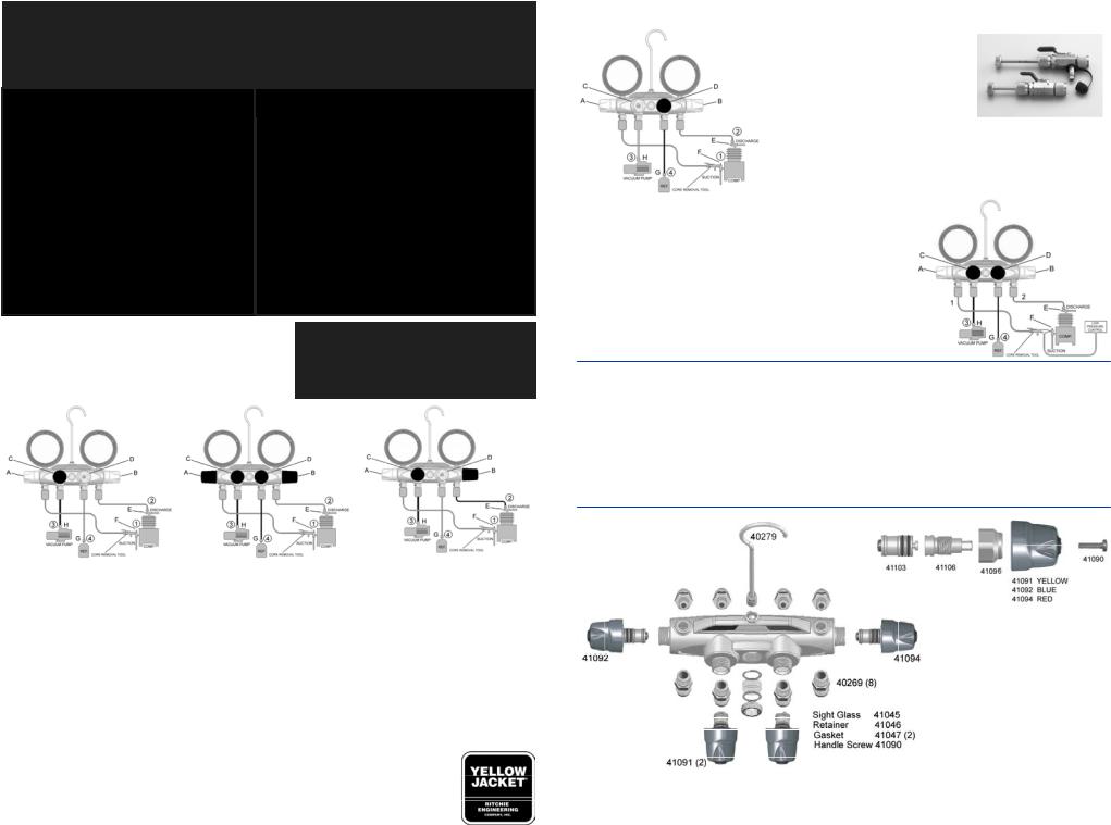
The various service and testing procedures below can be performed after the manifold gauge set has been installed as shown in the following diagrams.
# 1 # 2 # 4
I. TO PURGE HOSES BEFORE HOOKING UP
1 & 2 Connect hoses at E & F; do not
tighten
C & D Close valves
4Connect hose G to refrigerant
A & B Open valves
D & G Crack D & G valve to begin purge
E & F Tighten hose
II. TO OBSERVE OPERATING |
IV. TO CHARGE |
PRESSURES |
REFRIGERATION |
|
SUCTION (VAPOR) SIDE |
A & B Close valves C & D Close valves
1 & 2 Connect hoses as illustrated
E & F Crack open back seat
III. TO CHARGE REFRIGERATION SUCTION (VAPOR) SIDE WITH SCHRADERS
Purge as in I Charge as in IV
Purge as in I
4Connect hose G to refrigerant
AOpen valve
B& C Close valves
DOpen valve and throttle
F Crack front seat
Over-pressuring the gauge voids warranty
PROCEDURES, cont.
# 5 |
V. TO PULL VACUUM |
|
|
|
D |
Close valve |
|
|
H |
Connect hose 3 to pump |
|
|
C |
Open valve |
|
|
A & B Open valves |
#18975 |
|
|
E & F Mid position valves |
||
|
|
||
Note: To improve pull down time, use core removal tool (to minimize restrictions), and use minimum 3/8”or larger hose.
VI. TO SET LOW SIDE CONTROL BUILD UP PRESSURE |
# 6 |
|
Disconnect pressure control line. Using flare union, screw |
|
|
union into control line and other end of hose 1. |
|
|
B, C & D Close valves |
|
|
A |
Open valve |
|
EBack seat then crack open
FBack seat F
B |
Open to regulate pressure; set control |
REMOVING THE MANIFOLD FROM THE SYSTEM
After completing service operations, you must remove the manifold from the system without losing refrigerant or admitting air.
•Close valves E & C.
•Then open manifold valves A, B and D, 1/2 turn.
•Close valve F.
This arrangement will move all the high-pressure refrigerant from the line and the high-pressure gauge and put it into the low side. Close all manifold valves and remove hoses.
PARTS LIST
YELLOW JACKET Products Div.
Ritchie Engineering Company, Inc.
10950 Hampshire Avenue South
Bloomington, MN 55438-2623
U.S.A.
Phone: 952-943-1333
Fax: 1-800-322-8684
Int’l Fax: 952-943-1605
|
|
e-mail: custserv@yellowjacket.com |
Printed in U.S.A. |
P/N 510079E |
Web Site: www.yellowjacket.com |
|
 Loading...