


 Loading...
|
|
|
|
|
|
|
|
|
|
|
|
|
|
|
|
|
|
|
|
|
|
|
|
|
|
|
|
|
|
|
|
|
|
|
|
|
|
|
|
|
|
|
|
|
|
|
|
|
|
|
|
|
|
|
|
Operators Manual |
Models: |
|
|||||
|
|
|
|
|
ZHDD61270 |
|
|
|
|
|
|
|
ZHDD61340 |
|
|
|
|
|
|
|
ZHDD72340 |
|
|
Please read these instructions carefully and make sure you understand them before using the machine.
MANUAL NO. 106396 REV. 01 (06/10/03)

OPERATOR’S MANUAL
Contents |
|
Contents................................................................... |
1 |
Introduction ............................................................. |
3 |
Congratulations.................................................... |
3 |
General ................................................................ |
3 |
Driving and Transport on Public Roads ............... |
3 |
Towing ................................................................. |
3 |
Operating ............................................................. |
3 |
Good Service ....................................................... |
4 |
Manufacturing Number ........................................ |
4 |
Symbols and Decals ............................................... |
5 |
Safety Instructions.................................................. |
6 |
General Use......................................................... |
6 |
Driving on Slopes................................................. |
8 |
Children................................................................ |
9 |
Maintenance ........................................................ |
9 |
Transport............................................................ |
11 |
Controls ................................................................. |
12 |
Componen Locations ......................................... |
12 |
Throttle Control .................................................. |
13 |
Ignition ............................................................... |
13 |
Hour Meter ......................................................... |
13 |
Engaging the Mower Deck................................. |
14 |
Parking Brake .................................................... |
14 |
Seat Adjustment................................................. |
14 |
Motion Control Levers........................................ |
15 |
Hydraulic Lift Switch........................................... |
16 |
Refueling............................................................ |
17 |
Fuel Shut-Off...................................................... |
17 |
Fuses ................................................................. |
17 |
Hydraulic Lift for Mower Deck ............................ |
18 |
Lifting Lever for the Mower Deck (Manual) ........ |
18 |
Relays ................................................................ |
19 |
Accessories........................................................ |
19 |
Operation ............................................................... |
20 |
Before Starting ................................................... |
20 |
Starting the Engine ............................................ |
20 |
Running.............................................................. |
23 |
Mowing Tips....................................................... |
25 |
Stopping the Engine........................................... |
27 |
Moving by Hand ................................................. |
27 |
Maintenance .......................................................... |
28 |
Maintenance Schedule ...................................... |
28 |
Checking the Safety System.............................. |
27 |
Checking the Engine's Cooling Air Intake ......... |
31 |
Checking & Adjusting Throttle Cable ................ |
31 |
Clutch Service & Maintenance .......................... |
31 |
Replacing the Air Filter...................................... |
32 |
Replacing the Fuel Filter ................................... |
33 |
Checking Tire Pressures................................... |
33 |
Check & Filling Coolant System........................ |
33 |
Checking the Parking Brake.............................. |
34 |
Checking the Blades ......................................... |
34 |
Cleaning and Washing ...................................... |
35 |
Checking Hydraulic System .............................. |
35 |
Checking Battery............................................... |
36 |
Dampener Mounting.......................................... |
37 |
Reverse Detent Adjustment .............................. |
37 |
Motion Control Linkage Adjustment .................. |
37 |
Lubrication............................................................ |
39 |
Lubrication Schedule......................................... |
39 |
General ............................................................. |
39 |
Lubricating the Cables ...................................... |
40 |
Lubricating in Accordance with the Lubrication |
|
Schedule ........................................................... |
40 |
Trouble Shooting Guide ...................................... |
46 |
Storage.................................................................. |
49 |
Winter Storage .................................................. |
49 |
Service .............................................................. |
49 |
Technical Data...................................................... |
50 |
Measurements, Weights, Etc. ........................... |
50 |
Engine ............................................................... |
50 |
Noise Emissions and Cutting Width .................. |
51 |
Electrical System............................................... |
51 |
Transmission..................................................... |
51 |
Mower Deck ...................................................... |
51 |
Accessories....................................................... |
51 |
Service Journal .................................................... |
52 |
Delivery Service ................................................ |
52 |
After the First 50 Hours ..................................... |
53 |
Daily Service ..................................................... |
53 |
25-Hour Service ................................................ |
54 |
50-Hour Service ................................................ |
55 |
100-Hour Service .............................................. |
56 |
300-Hour Service .............................................. |
57 |
At Least Once Each Year.................................. |
58 |
Wiring Schematic ................................................. |
60 |
©2003 Yazoo/Kees Power Equipment.
All rights reserved.
Beartice, NE. Printed U.S.A.
1
2

INTRODUCTION
Introduction
Congratulations
Thank you for purchasing a Yazoo/Kees ride-on mower. This machine is built for the greatest efficiency and rapid mowing of large areas. Conveniant controls and a hydrostatic transmission regulated by steering levers also contribute to the machine’s performance.
This manual is a valuable document. Following the instructions (use, service, maintenance, etc.) can considerably increase the lifespan of your machine and even increase its resale value.
If you sell your machine, be sure to give the operator’s manual to the new owner.
The final chapter of this operator’s manual comprises a Service Journal. Ensure that service and repair work is documented. A well kept service journal reduces service costs for the season-based maintenance and affects the machine’s resale value. Take the operator’s manual along when the machine is left at the service center for service.
General
In this operator’s manual, left and right, backward and forward are used in relation to the machine’s normal driving direction.
Driving and Transport on Public Roads
Check applicable road traffic regulations before driving and transporting on public roads. If the machine is transported, you should always use approved fastening equipment and ensure that the machine is well anchored.
Operating
This machine is constructed only for mowing grass on lawns and other free and even ground without obstacles such as stones, tree stubs, etc. The machine can also be used for other tasks when equipped with special accessories provided by the manufacturer, for which the operating instructions are provided in conjunction with delivery. All other types of use are incorrect. The manufacturer’s directions concerning operation, maintenance, and repairs must be carefully followed.
The machine must only be operated, maintained, and repaired by persons that are familiar with the machine’s special characteristics and who are well versed in the safety instructions.
Accident prevention regulations, other general safety regulations, occupational safety rules, and traffic regulations must be followed without fail.
Unauthorized modifications to the design of the machine may absolve the manufacturer from liability for any resulting personal injury or property damage.
3

INTRODUCTION
Good Service
Yazoo/Kees’s products are sold only in specialized retail stores with complete service. This ensures that you as a customer receive only the best support and service. Before the product is delivered, the machine has, for example, been inspected and adjusted by your retailer, see the certificate in the Service Journal in this operator’s manual.
When you need spare parts or support in service questions, warranty issues, etc., please consult the following professional:
|
|
|
This Operator’s Manual belongs to the |
Engine |
Transmission |
machine with manufacturing number: |
|
|
|
|
|
Manufacturing Number
The machine’s manufacturing number can be found on the printed decal affixed to the left side of the frame under the seat.
•The machine’s type designation (I.D.).
•The manufacturer's type number (Model).
•The machine’s serial number (Serial no.)
Please state the type designation and serial number when ordering spare parts.
The engine’s manufacturing number is stated on a decal. This is placed on the right side on the top of the engine.
•The engine’s serial number (E/NO).
•The engine’s type designation (Code). Please state these when ordering spare parts.
The hydraulic pump’s manufacturing number is stated on a barcode decal affixed to the left side of the pump housing. The plate states:
•The pump’s type designation.
•The pump’s serial number.
The hydraulic motor’s manufacturing number is stated on a round metal plate. This is placed on the gable inside the motor. The plate states:
•The hydraulic motor’s type designation and design version.
•The hydraulic motor’s serial number.
4
SYMBOLS AND DECALS
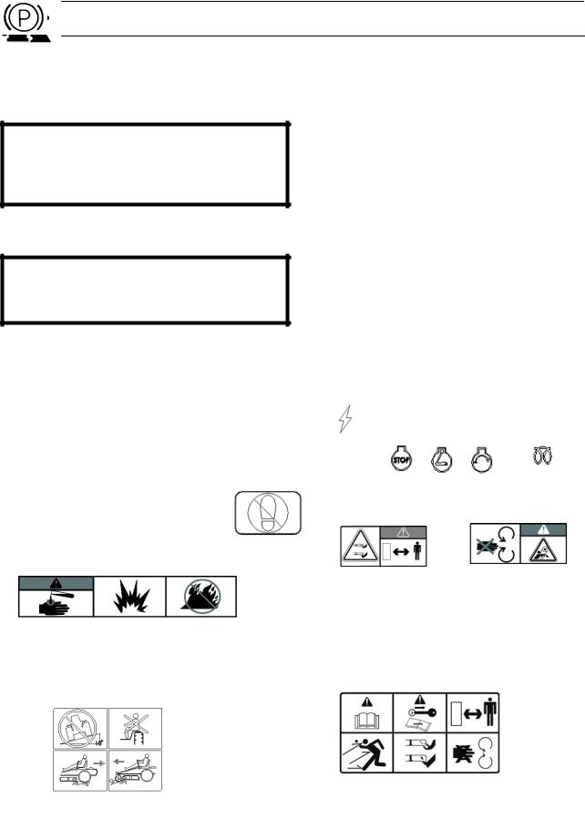
Symbols and Decals
These symbols are found on the machine and in the operator’s manual.
Study them carefully so that you know what they mean.
WARNING!
Xxxxxxx xxxx xxxxxxxx xxx x
Xxxxx xxxxxx xx.
xx xxxxxxxx xxxxx xxx xx.
Used in this publication to notify the reader of a risk of personal injury, particularly if the reader should neglect to follow instructions given in the manual.
IMPORTANT INFORMATION Xxxxxxx xxxx xxxxxxxx xxx xxx
xxxx xxxxxx xx.
Used in this publication to notify the reader of a risk of material damage, particularly if the reader should neglect to follow instructions given in the manual. Used also when there is a potential for misuse or misassembly.
R N
D
Reverse Neutral Fast |
Slow |
|
Electrical |
Ignition |
|
|
|
|
Diesel Fuel |
Power |
|
|
|
|
|
Accessory |
|
|
|
|
|
|
|
|
|
Glow plug |
|
|
|
|
Stop |
Run |
Start |
|
|
|
|
|
|
|
indicator |
Warning |
Parking brake |
|
Danger |
||
Do not stand here |
||
Caution |
||
|
Battery acid is corrosive, explosive, and flammable
Use on a slope no greater than 10°
No passengers
Careful backing up, Careful going forward, watch for other people watch for other people
Warning! Rotating |
Do not touch rotating |
blades, keep away from |
parts |
the discharge deck |
|
Shut off engine and remove key before performing any maintenace or repair work
Read |
Keep a safe |
Operators |
distance from |
Manual |
the machine |
|
Do not open |
Whole body |
or remove |
exposure to |
safety shields |
thrown objects Severing of fingers and toes |
while engine |
|
is running |
5
SAFETY INSTRUCTIONS
Safety Instructions
These instructions are for your safety. Read them carefully.
WARNING!
This symbol means that important safety instructions need to be emphasized. It concerns your safety.
General Use
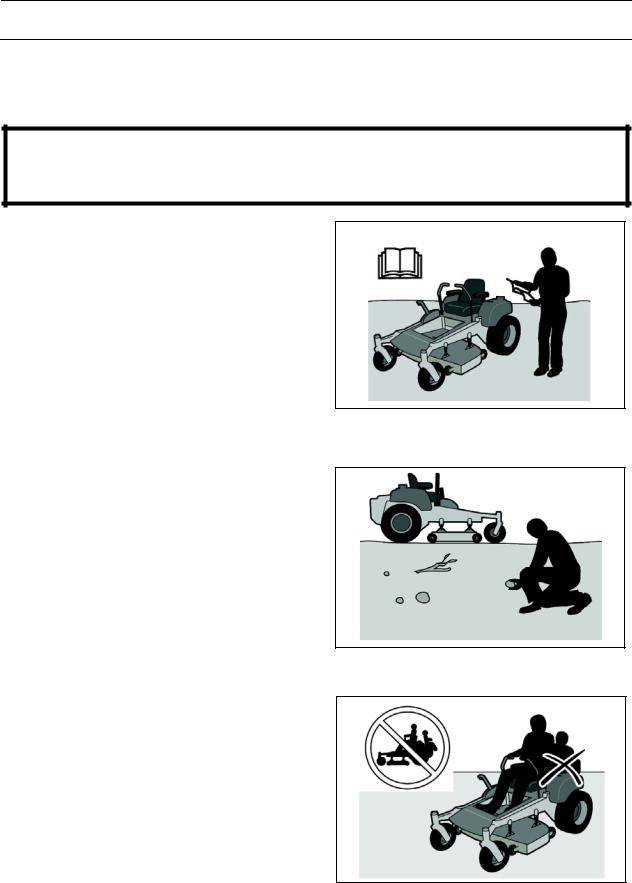
•Read all instructions in this operator’s manual and on the machine before starting it. Ensure that you understand them and then abide by them.
•Learn how to use the machine and its controls safely and learn how to stop quickly. Also learn to recognize the safety decals.
•Only allow the machine to be used by adults who are familiar with its use.
•Make sure nobody else is in the vicinity of the machine when you start the engine, engage the drive, or run the machine.
•Make sure animals and people maintain a safe distance from the machine.
•Stop the machine if someone enters the work area.
•Clear the area of objects such as stones, toys, steel wire, etc. that may become caught in the blades and thrown out.
•Beware of the discharge deck and do not point it at any one. Do not use the machine without the discharge deck in place.
•Stop the engine and prevent it from starting before you clean the discharge deck.
•Remember that the operator is responsible for dangers or accidents.
•Never take passengers. The machine is only intended for use by one person.
•Always look down and behind before and during reversing maneuvers. Keep a look out for both large and small obstacles.
•Slow down before turning.
•Shut down the blades when not mowing.
8011-512
Read the operator’s manual before starting the machine
8011-513
Clear the area of objects before mowing
8011-520
Never take passengers
6
SAFETY INSTRUCTIONS
•Be careful when rounding fixed objects, so that the blades do not hit them. Never drive over foreign objects.
•Only use the machine in daylight or in other well-lit conditions. Keep the machine a safe distance from holes or other irregularities in the ground. Pay attention to other possible risks.
•Never use the machine if you are tired, if you have consumed alcohol, or if you are taking other drugs or medication that can affect your vision, judgment, or coordination.
•Beware of traffic when working near or crossing a road.
•Never leave the machine unsupervised with the engine running. Always shut down the blades, pull back the parking brake, stop the engine, and remove the ignition key before leaving the machine.
•Never allow children or other persons not trained in the use of the machine to use or service it. Local laws may regulate the age of the user.
WARNING!
Engine exhaust and certain vehicle components contain or emit chemicals considered to cause cancer, birth defects, or other reproductive system damage. The engine exhaust contains carbon monoxide,
which is a colorless, poisonous gas. Do not use the machine
in enclosed spaces.
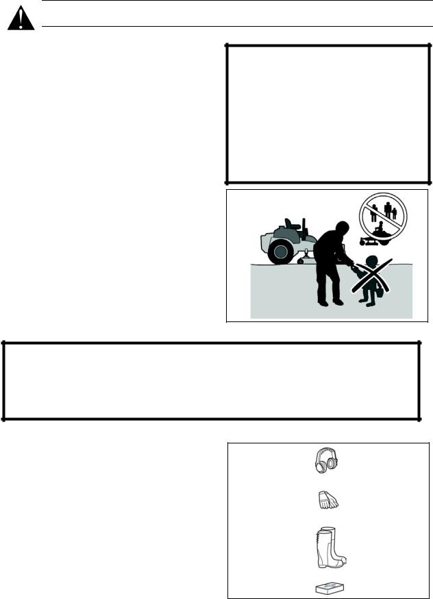
8011-518
Keep children away from the work area
WARNING!
When using the machine, approved personal protective equipment shall be used. Personal protective equipment cannot eliminate the risk of injury but it will reduce the degree of injury if an accident does happen. Ask your retailer for help in choosing the right equipment.
•Make sure that you have first aid equipment close at hand when using the machine.
•Never use the machine when barefoot. Always wear protective shoes or boots, preferably with steel toecaps.
•Always wear approved protective glasses or a full visor when assembling or driving.
•Never wear loose clothing that can get caught in moving parts.
8011-292
Personal protective equipment
7
SAFETY INSTRUCTIONS
Driving on Slopes
Driving on slopes is one of the operations where the risk is greatest that the driver will lose control or the machine will tip over, which can result in serious injury or death. All slopes require extra caution. If you cannot reverse up a slope or if you feel unsure,
do not mow the slope.
Do as follows
•Remove obstacles such as stones, tree branches, etc.
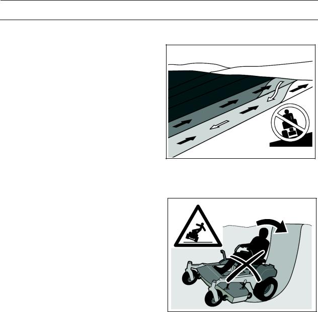
•Mow up and down, not side-to-side.
•Never drive the rider on terrain that slopes more than 10°.
•Avoid starting or stopping on a slope. If the tires begin to slip, shut down the blades and drive slowly down the slope.
•Always drive evenly and slowly on slopes.
•Make no sudden changes in speed or direction.
•Avoid unnecessary turns on slopes, and if it proves necessary, turn slowly and gradually downward, if possible.
•Watch out for and avoid driving over furrows, holes, and bumps. On uneven terrain, the machine can tip more easily. Long grass can hide obstacles.
•Drive slowly. Use small movements of the steering controls.
•Be extra cautious with any additional equipment, which can alter the machine’s stability.
•Do not mow near verges, ditches, or banks. The machine can suddenly spin around if a wheel goes over the edge of a drop or ditch, or if an edge gives way.
•Do not mow wet grass. It is slippery, and the tires can lose their grip, so that the machine slides.
•Try not to stabilize the machine by putting a foot on the ground.
•When cleaning the chassis, the machine may never be driven near verges or ditches.
6003-004
Mow up and down, not side-to-side
8011-519
Be extra cautious when driving on slopes
8
SAFETY INSTRUCTIONS
Children
•Serious accidents may occur if you fail to be on guard for children in the vicinity of the machine. Children are often attracted to the machine and mowing work. Never assume that children will stay put where you last saw them.
•Keep children away from the mowing area and under close supervision by another adult.
•Keep an eye out and shut off the machine if children enter the work area.
•Before and during a reversing maneuver, look backward and downward for small children.
•Never allow a child to ride with you. They can fall off and injure themselves seriously or prevent risk-free maneuvering of the machine.
•Never allow children to operate the
|
machine. |
8011-517 |
• |
Be particularly cautious near corners, |
Never allow children to operate the machine |
|
||
|
bushes, trees, or other objects that block |
|
|
your view. |
|
Maintenance
WARNING!
The engine must not be started when the driver’s floor plate or any protective plate for the mower deck’s drive belt is removed.
• |
Stop the engine. Prevent the engine from |
|
|
|
starting by removing the ignition key |
|
|
|
|
||
|
before making any adjustments or |
|
|
|
performing maintenance. |
|
|
• |
Never fill the fuel tank indoors. |
|
|
• |
Fuel and fuel fumes are poisonous and |
|
|
|
extremely flammable. Be especially |
|
|
|
cautious when handling fuel, as |
|
|
|
carelessness can result in personal |
|
|
|
injury or fire. |
|
|
• |
Only store fuel in containers approved for |
|
|
|
the purpose. |
|
|
• |
Never remove the fuel tank cap and never |
|
|
8011-516 |
|||
|
fill the fuel tank while the engine is running. |
||
|
Never fill the fuel tank indoors |
||
|
|
9
SAFETY INSTRUCTIONS
•Allow the engine to cool before refueling. Do not smoke. Do not fill fuel in the vicinity of sparks or open flames.
•If leaks arise in the fuel system, the engine must not be started until the problem has been resolved.
•Store the machine and fuel in such a way that there is no risk of leaking fuel or fuel vapor leading to damages.
•Check the fuel level before each use and leave space for the fuel to expand, because the heat from the engine and the sun may otherwise cause the fuel to expand and overflow.
•Avoid overfilling. If you spill fuel on the machine, wipe up the spill and wait until it has evaporated before starting the engine. If you have spilled fuel on your clothing, change your clothing.
•Allow the machine to cool before taking any actions in the engine compartment.
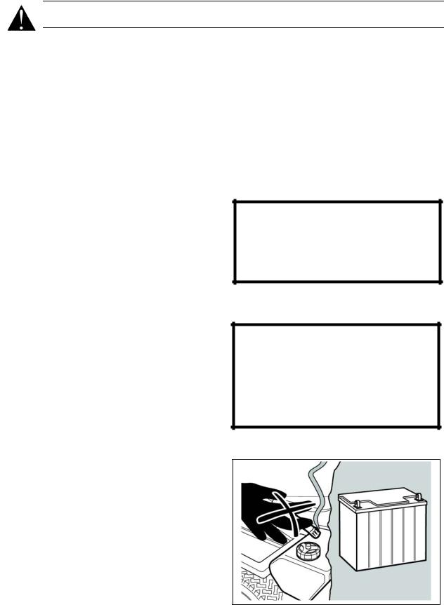
•Be very careful when handling battery acid. Acid on skin can cause serious corrosive burns. If you spill battery acid on your skin, rinse immediately with water.
•Acid in the eyes can cause blindness, contact a doctor immediately.
•Be careful when servicing the battery. Explosive gases form in the battery. Never perform maintenance on the battery when smoking or near open flames or sparks. The battery can explode and cause serious injury/damage.
•Ensure that nuts and bolts, especially the fastening bolts for the blade attachments, are properly tightened and that the equipment is in good condition.
•Do not modify safety equipment. Check regularly to be sure it works properly. The machine must not be driven with defective or unmounted protective plates, protective cowlings, safety switches, or other protective devices.
•Do not change the settings of governors and avoid running the engine with overly high engine speeds. If you run the engine too fast, you risk damaging the machine components.
WARNING!
The engine, the exhaust system, and the hydraulic system’s components become very warm during operation.
Risk for burns if touched.
WARNING!
The battery contains lead and lead compounds, chemicals that are considered to cause cancer, birth defects, and other reproductive system damage. Wash your hands after touching the battery.
8011-563
Do not smoke when performing maintenance on the battery. The battery can explode and cause serious injury/damage
10
SAFETY INSTRUCTIONS
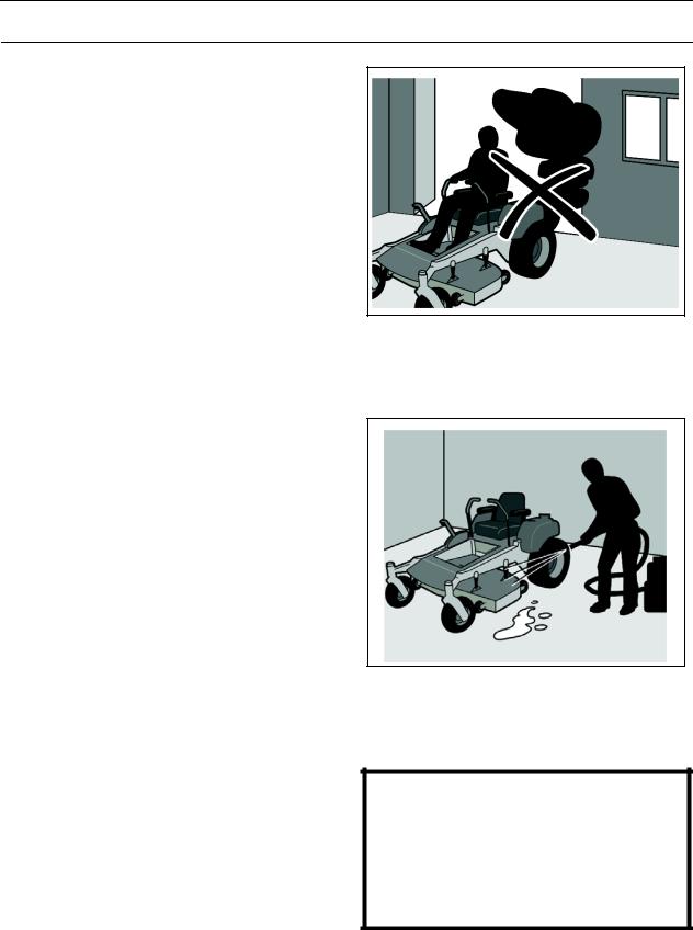
•Never use the machine indoors or in spaces lacking proper ventilation. The exhaust fumes contain carbon monoxide, an odorless, poisonous, and lethal gas.
•Stop and inspect the equipment if you run over or into anything. If necessary, make repairs before starting.
•Never make adjustments with the engine running.
•The machine is tested and approved only with the equipment originally provided or recommended by the manufacturer.
•The blades are sharp and can cause cuts and gashes. Wrap the blades or use protective gloves when handling them.
•Check the parking brake’s functionality regularly. Adjust and service as necessary.
•The mulch deck shall only be used when higher quality mowing is desired in familiar areas.
•Reduce the risk of fire by removing grass, leaves, and other debris that may have accumulated on the machine. Allow the machine to cool before putting it in storage.
Transport
•The machine is heavy and can cause serious crushing injuries. Be extra cautious when it is loaded on or unloaded from a vehicle or trailer.
•Use an approved trailer to transport the machine. Activate the parking brake, turn off the fuel supply, and fasten the machine with approved fastening devices, such as bands, chains, or ropes, when transporting.
•Check and abide by local traffic regulations before transporting or driving the machine on any road.
8011-515
Never drive the machine in an enclosed space
8011-514
Clean the machine regularly
IMPORTANT INFORMATION
The parking brake is not sufficient to lock the machine in place during transport. Ensure that the machine is well fastened to the transport vehicle. Reverse the machine onto the transport vehicle to avoid tipping it over.
11
CONTROLS
Presentation
This operator’s manual describes the Husqvarna Lever-Steered Rider Mower. The mower is fitted with a liquid cooled, 3 cylinder Daihatsu diesel engine (27 HP) or Daihatsu Turbo diesel engine (34 HP).
Transmission from the engine is made via two belt-driven hydraulic pumps, which in turn drive a hydraulic motor for each drive wheel. Using the left and right steering controls, the flow is regulated and thereby the direction and speed.
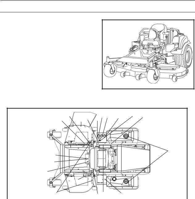
BAM-1
Lever-Steered Rider
14 |
18 |
15 16 |
17 |
4 |
9 |
13 |
12 |
|
|
|
|
|
2 |
|
8 |
|
|
|
|
|
|
|
5 |
|
|
|
|
7 |
|
|
|
|
3 |
|
|
|
|
1 |
10 6 |
11 |
Component Locations |
|
|
||
Component Locations |
|
|
||
1. |
Steering control left & right |
10. |
Seat adjustment lever |
|
2. |
Hour meter |
11. 12V DC adapter |
||
3. |
Parking brake |
12. |
Throttleregulates the engine speed |
|
4. |
Control for engaging the mower deck |
13. |
Cutting height adjuster |
|
5. |
Ignition |
14. |
Manual deck lift |
|
6. |
Relays |
15. |
Water temperature gauge |
|
7. |
Glow plug lamp |
16. |
Ammeter gauge |
|
8. |
Fuel tank caps |
17. |
Oil pressure gauge |
|
9. |
Fuel shut-off |
18. |
Hydraulic deck lift switch |
|
12
CONTROLS
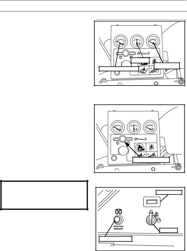
Gauges
Water temperature gaugeindicates coolant temperature and warns of overheat situation.
Ammeter - indicates amount of electrical flow at the battery. Under normal operating conditions the needle will be slightly on the plus (+) side of the gauge, showing that current is being supplied to the battery. At idle speed, the indicator may be at zero or on the negative (-) side. A continuous negative reading at normal operating speed indicates a malfunction in the charging system that should be checked immediately.
Oil pressure meter - tells what the pressure is in the oil system and warns if pressure is too low for operation.
Throttle Control
The throttle control regulates the engine speed.
In order to increase or decrease the engine speed, the control is moved forward or backward respectively.
Avoid idling the engine for long periods. Use full throttle when mowing.
Ignition
The ignition key is placed in the front console and is used to start the machine.
IMPORTANT INFORMATION
Wait till the glow plug light goes out before turning the engine over. To prolong starter life use short starting cycles, DO NOT exceed 30 secs./min.
Hour Meter
The hour meter displays the total operating time and reminds of service intervals.
Meter will indicate "CHG OIL" for engine oil and "SVC" for general service at preset intervals.
Service alerts will re-set after serveral hours.
AMMETER |
|
WATER TEMPERATURE |
OIL PRESSURE |
|
|
Gauges |
BAM-2 |
THROTTLE CONTROL
BAM-2
Throttle control
HOUR METER
IGNITION |
GLOW PLUG LIGHT
Console |
BAM-3 |
|
13
CONTROLS
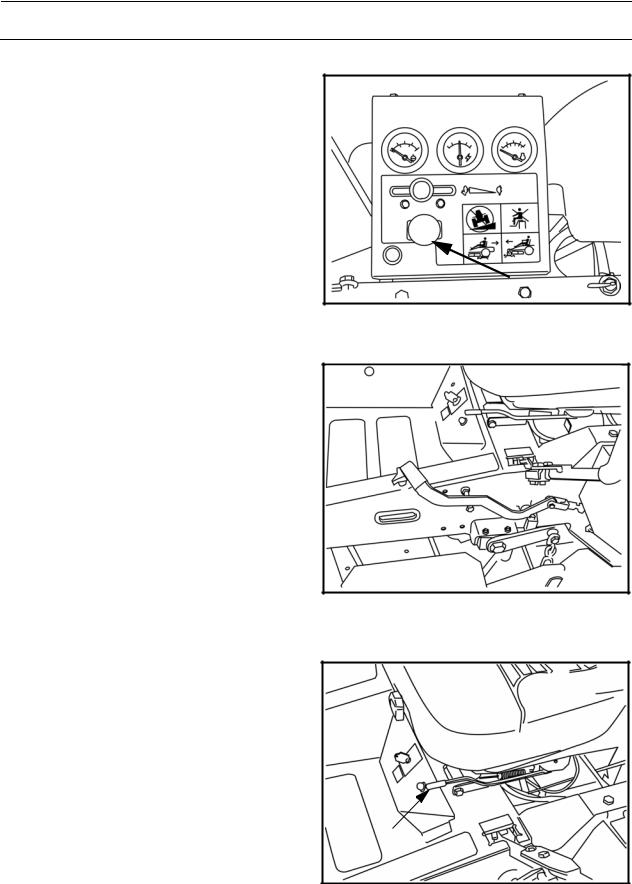
Engaging the Mower Deck
In order to engage the mower deck, pull the knob out; the mower deck is disengaged when the knob is depressed.
Deck should be engaged at mid throttle and disengaged at idle speed to prolong clutch life.
Parking Brake
The parking brake is found on the left of the machine. Pull the lever back to activate the brake and push forward to release it.
Seat Adjustment
Located on the left side of the seat is the seat adjustment lever. Pull outward to slide the seat either forward or backward.
Suspension resistence (weight) can be adjusted at the front of the seat.
Backrest tilt and lumbar support can also be adjusted using dials on the sides of the seat.
BAM-2
Engaging the mower deck
BAM-4
Parking brake not activated
BAM-5
Seat Adjustment Lever & suspension adjustment
14
CONTROLS
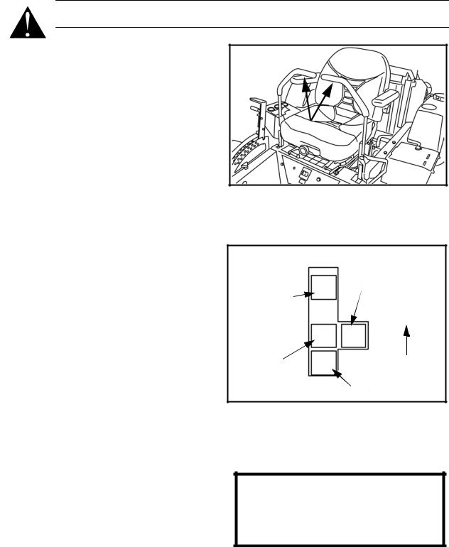
Motion Control Levers
The machine’s speed and direction are continuously variable using the two motion control levers. The motion control levers can be moved forward or backward from a neutral position. Furthermore, there is a neutral position, which is locked if the motion control levers are moved outward into the neutral slots.
When both controls are in the neutral position (N), the machine stands still.
The motion control levers on each side of the mower control the direction of movement. The left lever controls the flow of oil from the left hydro pump to the left wheel motor. The right lever controls the flow of oil from the right hydro pump to the right wheel motor.
NOTE: To begin motion, the operator must be in the seat and the parking brake disengaged before the motion control levers can be moved from the neutral slots or the engine will shut down.
By moving the levers an equal amount forward or back the machine will move in a straight line in that direction.
Movement of either lever forward will cause the right or left wheel to rotate in a forward direction. To stop movement pull both levers into the neutral position.
To turn right while moving in a forward direction pull the right lever back toward the neutral position, this will slow the rotation of the right wheel and cause the machine to turn in that direction.
To turn left while moving in a forward direction pull the left lever back towards the neutral position, this will slow the rotation of the left wheel and cause the machine to turn in that direction.
To zero turn pull one lever back beyond neutral while holding the other slightly ahead of neutral.
NOTE: The direction of the zero turn will be determined by which lever is pulled back beyond neutral. Thus left lever back, left zero turn and opposite for right zero turn. Use extra care when using this maneuver the machine can spin very rapidly if one lever is positioned too far ahead of the other.
Motion Control Levers |
BAM-6 |
|
NEUTRAL SLOT
NEUTRAL LOCK
FORWARD
NEUTRAL |
FRONT OF MOWER |
|
|
|
REVERSE |
Motion control lever pattern (right side)
WARNING!
The machine can turn very rapidly if one steering control is moved much further forward than the other.
15
CONTROLS
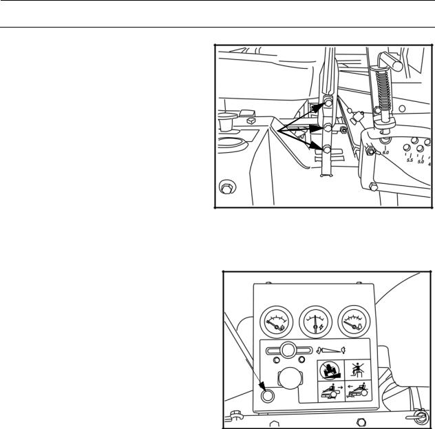
If the steering controls are in uneven positions when standing still, they can be adjusted using the adjustment screws, not the link system, for the controls
Adjusting screws
Hydraulic Lift Switch
Used to raise and lower the mower deck hydraulically. Only used on units with power deck lifts. Push switch forward to lower the deck and pull backward to raise the deck.
Hydraulic lift switch
BAM-7
BAM-2
16

CONTROLS
Refueling
The machine has two fuel tanks, one on each side just behind the seat. The tanks hold 11.4 gallons, 5.7 gallons each.
The engine is run on clean, fresh, diesel fuel with a minumum of 40 cetane.
.
WARNING!
Diesel fuel is highly flammable. Observe caution and fill the tank outdoors (see the safety rules).
Fuel Tanks
BAM-8
Fuel Shut-Off
The fuel shut-off is placed to the right side of the seat. The shut-off has three positions; right tank, left tank and off position.
Fuses
The fuses are located in a fuse block to the right of the battery. They are flat pin fuses of the same type used in automobiles.
There are five fuses.
Fuse ratings and functions moving from the top:
•20A - accesory jack
•7.5A - sub system
•10A - PTO/clutch
•30A - hydrualic deck lift
•50A - main system fuse (in line)
Fuel Shut-Off |
BAM-9 |
|
20A |
7.5A |
30A |
50A |
10A |
BAM-10
Fuses
17
CONTROLS
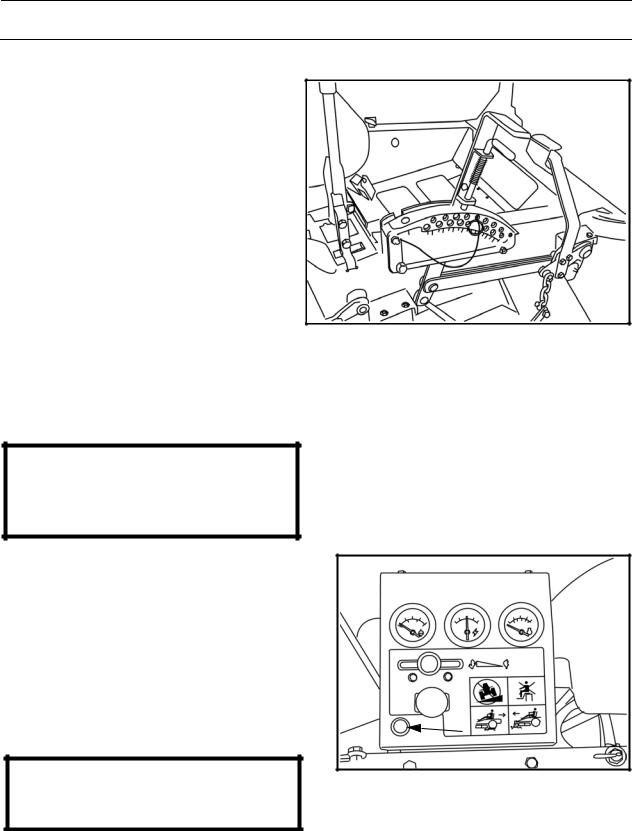
Manual Lifting Lever with Foot Assist for the Mower Deck
The lifting lever is used to place the mower deck in the transport position or one of the 17 different cutting height positions.
The cutting height is set by placing a pin in the hole for the desired cutting height and the pin is then locked on the inside (hidden in the illustration) with the supplied cotter pin.
1.Pull the lever backward while pushing on the foot pedal, lifting the deck to the locked position. The deck is then raised.
2.Depress the lock handle, counter hold, and move the lifting lever forward toward the pin to engage the set cutting height.
The deck is then lowered. |
The mower deck’s lifting lever and foot pedal |
|
3.The lifting lever can also be used to temporarily adjust the cutting height, such as when passing a minor bump in the lawn.
BAM-11
IMPORTANT INFORMATION
In order to obtain an even cutting height it is important that the air pressure in all four tires is the same (16 psi).
Hydraulic Lift for the Mower Deck
1.Place pin in the appropriate hole for desired cutting height, secure with cotter pin.
2.Push switch forward on the console to lower deck to the set cutting height.
3.Pull backwards on the switch on the console to raise the deck for transport.
IMPORTANT INFORMATION
Hydraulic switch
Pin must be locked into a hole for transport or mowing.
BAM-2
18
Loading...