


 Loading...
YASNAC PC NC
Programming Manual
Version: Beta 1.0
YASNAC PCNC Programming Manual |
Introduction |
|
|
SAFETY INFORMATION
PRECAUTIONS
1.Read this instruction manual in its entirety before using the operating functions available in the YASNAC PCNC.
2.The following warning symbols are used to indicate precautions that the user must be aware of to safely use this equipment. Failure to follow these precautions can result in serious or possibly even fatal injury and damage to products or related equipment or systems.

 WARNING
This symbol indicates the presence of a potentially hazardous condition which, if not avoided, could result in serious personal injury or death.
This precautionary symbol appears in labels attached to YASNAC products to alert the user to conditions requiring concern for safety.
SPECIAL SAFETY NOTE: This symbol indicates that ELECTRICAL SHOCK HAZARD condition exists. DO NOT TOUCH any electrical connection terminals when the power is on, and for at least 5 minutes after switching off the power supply. Warning label is located on the PCNC
PCNC Unit
xxxxxxxxx  WARNING LABEL
xxxxxxxxx xxxxxxxxx xxxxxxxxx xxxxxxxxx
NOTICE
Printed _______. 1999. The information contained within this document is the proprietary property of Yasakawa Electric America, Inc., and may not be copied, reproduced or transmitted to other parties without the expressed written authorization of Yasakawa Electric America, Inc.
No pattent liability is assumed with respect to the uses of the information contained herein. Moreover, because Yaskawa is constantly improving its high quality product, the information contained in this manual is subject to change without notice. Every precaution has been taken in the preparation of this document.
i

YASNAC PCNC Programming Manual |
Introduction |
INFORMATION INDICATORS
The following symbols are used in this operating manual to emphasize particular information to the user:
POINT |
Indicates important information to be remembered, i.e., precautionary alarm |
displays to prevent damaging devices. |
SUPPLEMENT 
 Indicates supplementary material.
TERMS Indicates definitions of terminology that has not been explained before.
NOTES REGARDING SAFE OPERATION
It is important that the user should read this manual before installing, operating, performing any maintenance or inspecting the <$61$& 3& 1& Also, the functions and performance of a NC machine tool are not determined by the CNC unit itself, therefore thoroughly read and familiarize yourself with the machine builder’s documentation concerning the safe and most efficient ways to use the machine tool. Nevertheless, Yasakawa assumes no responsibility for damages resulting from the use of the information contained within this publication.
ii

YASNAC PCNC Programming Manual Introduction
Table of Contents
1. PROGRAMMING BASICS |
|
1.1 FUNDAMENTALS OF PROGRAMMING TERMINOLOGY . . . . . . . . . . . . . . . . |
1-2 |
1.1.1Numerically Controlled Axes and the Number of Simultaneously Controllable
Axes . . . . . . . . . . . . . . . . . . . . . . . . . . . . . . . . . . . . . . . . . . . . . . . . . . . . . . . .1-2 1.1.2 Least Input Increment and Least Output Increment . . . . . . . . . . . . . . . . . . .1-6 1.1.3 Maximum Programmable Values for Axis Movement . . . . . . . . . . . . . . . . .1-8 1.1.4 Optional Block Skip (/1), (/2 to /9) * . . . . . . . . . . . . . . . . . . . . . . . . . . . . . .1-11 1.1.5 Buffer Register and Multi-active Register . . . . . . . . . . . . . . . . . . . . . . . . . .1-12
1.2 BASICS OF FEED FUNCTION . . . . . . . . . . . . . . . . . . . . . . . . . . . . . . . . . . . . . . .1-13 1.2.1 Rapid Traverse . . . . . . . . . . . . . . . . . . . . . . . . . . . . . . . . . . . . . . . . . . . . . . .1-13 1.2.2 Cutting Feed (F Command) . . . . . . . . . . . . . . . . . . . . . . . . . . . . . . . . . . . . .1-13 1.2.3 F1-Digit Feed* . . . . . . . . . . . . . . . . . . . . . . . . . . . . . . . . . . . . . . . . . . . . . . .1-16 1.2.4 Feed per Minute Function (G94) . . . . . . . . . . . . . . . . . . . . . . . . . . . . . . . . .1-18 1.2.5 Solid Tap Mode (G93, G94) * . . . . . . . . . . . . . . . . . . . . . . . . . . . . . . . . . . .1-18 1.2.6 Automatic Acceleration and Deceleration . . . . . . . . . . . . . . . . . . . . . . . . . .1-19
2. COMMAND CALLING AXIS MOVEMENTS |
|
|
2.1 |
INTERPOLATION COMMANDS . . . . . . . . . . . . . . . . . . . . . . . . . . . . . . . . . . . . |
. .2-2 |
|
2.1.1 Positioning (G00, G06, G60) . . . . . . . . . . . . . . . . . . . . . . . . . . . . . . . . . . . . |
.2-2 |
|
2.1.2 Linear Interpolation (G01) . . . . . . . . . . . . . . . . . . . . . . . . . . . . . . . . . . . . . . |
.2-4 |
|
2.1.3 Circular Interpolation (G02, G03) . . . . . . . . . . . . . . . . . . . . . . . . . . . . . . . . |
.2-5 |
|
2.1.4 Helical Interpolation (G02, G03)* . . . . . . . . . . . . . . . . . . . . . . . . . . . . . . . . |
2-11 |
2.2 |
REFERENCE POINT RETURN . . . . . . . . . . . . . . . . . . . . . . . . . . . . . . . . . . . . . . . |
2-13 |
|
2.2.1 Automatic Return to Reference Point (G28) . . . . . . . . . . . . . . . . . . . . . . . . |
2-13 |
|
2.2.2 Reference Point Return Check (G27) . . . . . . . . . . . . . . . . . . . . . . . . . . . . . |
2-17 |
|
2.2.3 Return from Reference Point Return (G29) . . . . . . . . . . . . . . . . . . . . . . . . |
2-18 |
|
2.2.4 Second to Fourth Reference Point Return (G30) . . . . . . . . . . . . . . . . . . . . . |
2-22 |
iii
YASNAC PCNC Programming Manual |
Introduction |
||
|
|
||
3. MOVEMENT CONTROL COMMANDS |
|
||
3.1 SETTING THE COORDINATE SYSTEM . . . . . . . . . . . . . . . . . . . . . . . . . . |
. . . . .3-3 |
||
|
3.1.1 Selecting the Coordinate System . . . . . . . . . . . . . . . . . . . . . . . . . . . . . . |
. . . .3-3 |
|
|
3.1.2 Base Coordinate System (G92) . . . . . . . . . . . . . . . . . . . . . . . . . . . . . . . |
. . . .3-3 |
|
|
3.1.3 Workpiece Coordinate System (G54 to G59)* . . . . . . . . . . . . . . . . . . . |
. . . .3-5 |
|
|
3.1.4 Local Coordinate System (G52 Q2)* . . . . . . . . . . . . . . . . . . . . . . . . . . |
. . .3-12 |
|
|
3.1.5 Machine Coordinate System (G53) . . . . . . . . . . . . . . . . . . . . . . . . . . . . |
. . .3-13 |
|
|
3.1.6 Rotation of Coordinate System (G68, G69)* . . . . . . . . . . . . . . . . . . . . |
. . .3-16 |
|
|
3.1.7 Plane Selection (G17, G18, G19) . . . . . . . . . . . . . . . . . . . . . . . . . . . . . |
. . .3-18 |
|
3.2 DETERMINING THE COORDINATE VALUE INPUT MODES . . . . . . . . . |
. . .3-19 |
||
|
3.2.1 Absolute/Incremental Designation (G90, G91) . . . . . . . . . . . . . . . . . . . |
. . .3-19 |
|
|
3.2.2 Inch/Metric Input Designation (G20, G21) . . . . . . . . . . . . . . . . . . . . . . |
. . .3-21 |
|
|
3.2.3 |
Scaling (G50, G51) * . . . . . . . . . . . . . . . . . . . . . . . . . . . . . . . . . . . . . . . |
. . .3-22 |
3.3 |
TIME-CONTROLLING COMMANDS . . . . . . . . . . . . . . . . . . . . . . . . . . . . . . |
. . .3-26 |
|
|
3.3.1 |
Dwell (G04) . . . . . . . . . . . . . . . . . . . . . . . . . . . . . . . . . . . . . . . . . . . . . . |
. . .3-26 |
|
3.3.2 |
Exact Stop (G09) . . . . . . . . . . . . . . . . . . . . . . . . . . . . . . . . . . . . . . . . . . |
. . .3-26 |
|
3.3.3 Exact Stop Mode (G61, G64) . . . . . . . . . . . . . . . . . . . . . . . . . . . . . . . . |
. . .3-26 |
|
3.4 |
TOOL OFFSET FUNCTIONS . . . . . . . . . . . . . . . . . . . . . . . . . . . . . . . . . . . . . |
. . .3-28 |
|
|
3.4.1 Tool Offset Data Memory . . . . . . . . . . . . . . . . . . . . . . . . . . . . . . . . . . . |
. . .3-28 |
|
|
3.4.2 Tool Length Offset (G43, G44, G49) . . . . . . . . . . . . . . . . . . . . . . . . . . |
. . .3-29 |
|
|
3.4.3 Tool Position Offset (G45 to G48) . . . . . . . . . . . . . . . . . . . . . . . . . . . . |
. . .3-32 |
|
|
3.4.4 Radius Offset C Function (G40, G41, G42) * . . . . . . . . . . . . . . . . . . . . |
. . .3-40 |
|
|
3.4.5 3-Dimensional Tool Offset Function (G40, G41, G42)* . . . . . . . . . . . |
. . .3-78 |
|
3.5 S, T, M, AND B Functions . . . . . . . . . . . . . . . . . . . . . . . . . . . . . . . . . . . . . . . . |
. . .3-85 |
||
|
3.5.1 Spindle Function (S Function) . . . . . . . . . . . . . . . . . . . . . . . . . . . . . . . . |
. . .3-85 |
|
|
3.5.2 Tool Function (T Function) . . . . . . . . . . . . . . . . . . . . . . . . . . . . . . . . . . |
. . .3-86 |
|
|
3.5.3 Miscellaneous Function (M Function) . . . . . . . . . . . . . . . . . . . . . . . . . |
. . .3-87 |
|
|
3.5.4 Second Miscellaneous Function (B Function) * . . . . . . . . . . . . . . . . . . |
. . .3-89 |
|
iv
YASNAC PCNC Programming Manual |
Introduction |
||
|
|
|
|
4.1 |
PROGRAM SUPPORT FUNCTIONS (1) . . . . . . . . . . . . . . . . . . . . . . . . . . . |
. . . . .4-3 |
|
|
4.1.1 Canned Cycles (G73 to G89, G181 to G189) * . . . . . . . . . . . . . . . . . . . |
. . . .4-3 |
|
|
4.1.2 Hole Machining Pattern Cycles (G70, G71, G72) * . . . . . . . . . . . . . . . |
. . .4-32 |
|
|
4.1.3 Solid Tap Function (G84, G74) * . . . . . . . . . . . . . . . . . . . . . . . . . . . . . |
. . .4-36 |
|
|
4.1.4 Deep-hole Solid Tap Function (G184, G174)* . . . . . . . . . . . . . . . . . . . |
. . .4-46 |
|
|
4.1.5 Circle Cutting Function (GI2, G13) . . . . . . . . . . . . . . . . . . . . . . . . . . . |
. . .4-57 |
|
|
4.1.6 Mirror Image ON/OFF (M94, M95) * . . . . . . . . . . . . . . . . . . . . . . . . . . |
. . .4-61 |
|
|
4.1.7 Programmable Data Input (G10) * . . . . . . . . . . . . . . . . . . . . . . . . . . . . |
. . .4-64 |
|
|
4.1.8 Subprogram Call Up Function (M98, M99) . . . . . . . . . . . . . . . . . . . . . |
. . .4-67 |
|
4.2 |
PROGRAM SUPPORT FUNCTIONS (2) . . . . . . . . . . . . . . . . . . . . . . . . . . . . |
. . .4-69 |
|
|
4.2.1 |
Program Copy (G25)* . . . . . . . . . . . . . . . . . . . . . . . . . . . . . . . . . . . . . . |
. . .4-69 |
|
4.2.2 Automatic Corner Override (G106) * . . . . . . . . . . . . . . . . . . . . . . . . . . |
. . .4-72 |
|
|
4.2.3 Stored Stroke Limit B and C (G22, G23) * . . . . . . . . . . . . . . . . . . . . . . |
. . .4-77 |
|
|
4.2.4 |
Break Point Function . . . . . . . . . . . . . . . . . . . . . . . . . . . . . . . . . . . . . . . |
. . .4-82 |
|
4.2.5 |
High-speed Cutting * . . . . . . . . . . . . . . . . . . . . . . . . . . . . . . . . . . . . . . . |
. . .4-82 |
|
4.2.6 Chamfering and Corner Rounding Commands * . . . . . . . . . . . . . . . . . |
. . .4-85 |
|
|
4.2.7 Corner Feedrate Designation (G107, G108)’ . . . . . . . . . . . . . . . . . . . . |
. . .4-89 |
|
4.3 |
AUTOMATING SUPPORT FUNCTIONS . . . . . . . . . . . . . . . . . . . . . . . . . . . |
. .4-102 |
|
|
4.3.1 Skip Function (G31) * . . . . . . . . . . . . . . . . . . . . . . . . . . . . . . . . . . . . . . |
. .4-102 |
|
|
4.3.2 Program interrupt Function (M90, M91)* . . . . . . . . . . . . . . . . . . . . . . . |
. .4-105 |
|
|
4.3.3 Tool Life Control Function * . . . . . . . . . . . . . . . . . . . . . . . . . . . . . . . . . |
. .4-107 |
|
4.4 |
MACROPROGRAMS . . . . . . . . . . . . . . . . . . . . . . . . . . . . . . . . . . . . . . . . . . . . |
. .4-114 |
|
|
4.4.1 |
Differences from Subprograms . . . . . . . . . . . . . . . . . . . . . . . . . . . . . . . |
. .4-114 |
|
4.4.2 Microprogram Call (G65, G66, G67) . . . . . . . . . . . . . . . . . . . . . . . . . . |
. .4-115 |
|
|
4.4.3 |
Variables . . . . . . . . . . . . . . . . . . . . . . . . . . . . . . . . . . . . . . . . . . . . . . . . |
. .4-126 |
|
4.4.4 |
Operation Instructions . . . . . . . . . . . . . . . . . . . . . . . . . . . . . . . . . . . . . . |
. .4-155 |
|
4.4.5 |
Control Instructions . . . . . . . . . . . . . . . . . . . . . . . . . . . . . . . . . . . . . . . . |
. .4-157 |
|
4.4.6 |
Registering the Microprogram . . . . . . . . . . . . . . . . . . . . . . . . . . . . . . . . |
. .4-163 |
|
4.4.7 |
Microprogram Alarm Numbers . . . . . . . . . . . . . . . . . . . . . . . . . . . . . . . |
. .4-164 |
|
4.4.8 |
Examples of Microprograms . . . . . . . . . . . . . . . . . . . . . . . . . . . . . . . . . |
. .4-165 |
v

YASNAC PCNC Programming Manual |
Introduction |
USING THIS MANUAL
This manual decribes the procedures for operating the <$61$& 3& 1& .
RELATED INFORMATION SOURCES
For additonal information, refer to the following manuals:
TITLE OF DOCUMENT |
CONTENTS |
|
|
|
|
|
|
|
YASNAC PCNC Programming Manual |
PCNC Program creation instructions |
|
(YEA-SIA-C844-2.2) |
||
|
||
|
|
|
YASNAC PCNC/PLC Programming Manual |
PLC Program creation instructions |
|
(YEA-SIA-C844-0.1) |
||
|
||
|
|
|
YASNAC PCNC I/O Signal Manual |
Describes functions between PCNC and PLC |
|
(YEA-SIA-C844-2.3) |
||
|
||
|
|
|
YASNAC PCNC Connection Manual |
Instructions for connecting PCNC with machines, |
|
(YEA-SIA-C844-0.2) |
machine interface and peripheral equipment |
|
|
|
|
YASNAC PCNC Maintenance Manual |
Describes service and maintenance procedures. |
|
(YEA-SIA-C844-2.9) |
||
|
||
|
|
CAUTIONS
This manual describes all the option functions (identified by the “*” symbol) but some of these may not be available with your YASNAC PCNC. To determine the option functions installed in your PCNC, refer to the specification document or manuals published by the machine tool builder.
Unless otherwise specified, the following conditions apply in programming explanations and programming examples.
lMetric system for input and metric system for output / movement
lZero point in the base coordinate system
lReference point
Yaskawa has made every effort to describe individual functions and their relationships to other functions as accurately as possible. However, there are many things that cannot or must not be performed and it is not possible to describe all of these. Accordingly, readers are requested to understand that unless it is specifically stated that something can be performed, it should be assumed that it cannot be performed.
Also, bear in mind that the performance and functions of an PCNC machine tool are not determined solely by the PCNC unit. The entire control system consists of the mechanical system, then machine operation panel and other machine related equipment in addition to the PCNC. Therefore, read the manuals published by the machine tool builder for detailed information relating to the machine.
vi
YASNAC PCNC Programming Manual |
Chapter 1: Programming Basics |
|
|
1
Programming Basics
Chapter 1 describes the basic terms used in programming and the feed functions.
1.1 FUNDAMENTALS OF PROGRAMMING TERMINOLOGY . . . . . . . . . . . . . . . 1-2
1.1.1Numerically Controlled Axes and the Number of Simultaneously Controllable
Axes . . . . . . . . . . . . . . . . . . . . . . . . . . . . . . . . . . . . . . . . . . . . . . . . . . . . . . . 1-2 1.1.2 Least Input Increment and Least Output Increment . . . . . . . . . . . . . . . . . . 1-6 1.1.3 Maximum Programmable Values for Axis Movement . . . . . . . . . . . . . . . . 1-8 1.1.4 Optional Block Skip (/1), (/2 to /9) * . . . . . . . . . . . . . . . . . . . . . . . . . . . . . 1-11 1.1.5 Buffer Register and Multi-active Register . . . . . . . . . . . . . . . . . . . . . . . . . 1-12
1.2 BASICS OF FEED FUNCTION . . . . . . . . . . . . . . . . . . . . . . . . . . . . . . . . . . . . . . 1-13 1.2.1 Rapid Traverse . . . . . . . . . . . . . . . . . . . . . . . . . . . . . . . . . . . . . . . . . . . . . . 1-13 1.2.2 Cutting Feed (F Command) . . . . . . . . . . . . . . . . . . . . . . . . . . . . . . . . . . . . 1-13 1.2.3 F1-Digit Feed* . . . . . . . . . . . . . . . . . . . . . . . . . . . . . . . . . . . . . . . . . . . . . . 1-16 1.2.4 Feed per Minute Function (G94) . . . . . . . . . . . . . . . . . . . . . . . . . . . . . . . . 1-18 1.2.5 Solid Tap Mode (G93, G94) * . . . . . . . . . . . . . . . . . . . . . . . . . . . . . . . . . . 1-18 1.2.6 Automatic Acceleration and Deceleration . . . . . . . . . . . . . . . . . . . . . . . . . 1-19
1 - 1
YASNAC PCNC Programming Manual |
Chapter 1: Programming Basics |
|
|
1.1 FUNDAMENTALS OF PROGRAMMING TERMINOLOGY
This section describes the “basic terms used in programming.
1.1.1Numerically Controlled Axes and the Number of Simultaneously Controllable Axes
(1)Numerically Controlled Axes and Axes Names
The numerically controlled axes and the axis names are indicated in Table 1.1.1.1.
Table 1.1.1.1: Numerically Controlled Axes
Controlled Axis |
Axis Name |
Model Name Description |
|
|
|
|
|
Basic axes |
X, Y, Z |
Represents the coordinate position or distance in or along an axis |
|
indicated by X, Y, and Z. |
|||
|
|
||
|
|
|
|
* |
A, B, C |
Represents the commands of the fourth and fifth axes. For rotary |
|
or |
motion, address characters A, B, and C are used and for parallel (lin- |
||
4th and 5th axes |
|||
U, V, W |
ear) motion, address characters U, V, and W are used. |
||
|
|||
|
|
|
(2)Number of Simultaneously Controllable Axes
With the standard specification, up to three axes can be controlled simultaneously. This number can be increased optionally to four and five axes.
(a)Number of simultaneously controllable axes with the 3-axis control function The number of simulta.neously controllable axes is indicated in Table 1.2.
Table 1.1.1.2: The Number of Simultaneously Controllable Axes with 3-axis
Control Function
|
Number of Simultaneously Controllable Axes |
|
|
Positioning (G00) |
3 axes (X-, Y-, and Z-axis) |
|
|
Linear interpolation (G01) |
3 axes (X-, Y-, and Z-axis) |
|
|
Circular interpolation (G02, G03) |
2 axes (X- and Y-axis, Y- and Z-axis, or Z- and X-axis) |
*Circle cutting (G12, G13) |
2 axes (X- and Y-axis) |
|
|
||
|
|
2 axes (circular interpolation in XY plane) |
Simultaneous |
||
*Helical interpolation (G02, G03) |
1 axis (linear interpolation, Z-axis) |
||||
3-axis control |
|||||
|
|
See 2.1.4, “Helical Interpolation (G02, G03)”. |
|||
|
|
|
|
||
|
|
|
|
||
Manual operation |
3 axes (X-, Y-, and Z-axis) |
|
|
||
|
|
|
|||
Note 1: |
The plane in which circular interpolation is executed is determined by the plane selection G |
||||
|
code (G 17 to G19) which is presently valid. For details, see 2.1.3, “Circular Interpolation |
||||
|
(G02, G03)”. |
|
|
|
|
2:With a manual pulse generator, simultaneous control is possible in either one or three axes.
1 - 2

YASNAC PCNC Programming Manual |
Chapter 1: Programming Basics |
|
|
(b)Number of simultaneously controllable axes with the 4-axis control function*
The fourth axis can be selected optionally. In this manual, the fourth axis is referred to as “a-axis” and represents any of six axes – A, B, C, U, V, and W. Which address characters should be used for the fourth axis is set for parameters pm1109, pm1110, and pm1111, and pm1151, pm1152, and pm1153. The number of simultaneously controllable axes is indicated in Table 1.3.
Table 1.1.1.3: The Number of Simultaneously Controllable Axes with 4-axis
Control Function
|
Number of Simultaneously Controllable Axes |
||
|
|
|
|
Positioning (G00) |
4 axes (X-. Y-, Z-, and a-axis) |
|
|
|
|
|
|
Linear interpolation (G01) |
4 axes (X-. Y-, Z-, and a-axis) |
|
|
|
|
||
Circular interpolation (G02, G03) |
2 axes (X- and Y-axis, Y- and Z-axis, or Z- and X-axis) |
||
2 axes (X- and a-axis, Y- and a-axis, or Z- and α -axis) |
|||
|
|||
|
|
|
|
*Circle cutting (G12, G13) |
2 axes (X- and Y-axis) |
|
|
|
|
|
|
|
2 axes (circular interpolation in XY plane) |
Simultaneous |
|
*Helical interpolation (G02, G03) |
1 axis (linear interpolation, Z-axis) |
||
3-axis control |
|||
|
See 2.1.4, “Helical Interpolation (G02, G03)”. |
||
|
|
||
|
|
|
|
Manual operation |
4 axes (X-, Y-, and a-axis) |
|
|
|
|
|
|
Note 1: |
If “a” is included in circular interpolation, it must be a linear axis (U, V, or W). The plane in |
|
which circular interpolation is executed is determined by the plane selection G code (G17 to |
|
G19) which is presently valid. For details, see 2.1.3, “Circular Interpolation (G02, G03)”. |
2:With a manual pulse generator, simultaneous control is possible in either one or three axes.
For the a-axis, either a rotary axis or a linear axis can be selected.
•A rotary axis (A-, B-, or C-axis) is defined as indicated in Table 1.4.
Table 1.1.1.4: |
Rotary Axes |
|
|
|
|
|
Rotary Axis |
Definition |
|
|
|
|
A-axis |
Rotary axis around an axis which is parallel to X-axis |
|
|
|
|
B-axis |
Rotary axis around an axis which is parallel to Y-axis |
|
|
|
|
C-axis |
Rotary axis around an axis which is parallel to Z axis |
|
|
|
Note 1: |
The unit of output increment (motion increment) and input increment for a rotary axis is |
|
“degrees” instead of ‘“mm” which is used for a linear axis (X-, Y-,Z-axis). With the exception |
|
of the unit, a rotary axis can be treated in the same manner as a linear axis. (Metric system) |
|
(The NC circulates feedrate assuming 0.001 deg. as 0.001 mm.) |
2:Even if the dimensions are changed to inches by using the inch/mm selection function, the unit system for a rotary axis remains unchanged (degrees).
1 - 3
YASNAC PCNC Programming Manual |
Chapter 1: Programming Basics |
|
|
•A linear axis (U-, V-, or W-axis) is defined as indicated in Table 1.5.
Table 1.1.1.5: |
Linear Axes |
|
|
|
|
|
Linear Axis |
Definition |
|
|
|
|
U-axis |
A linear axis parallel to X-axis. |
|
|
|
|
V-axis |
A linear axis parallel to Y-axis. |
|
|
|
|
W-axis |
A linear axis parallel to Z-axis. |
|
|
|
Note 1: |
The unit of output increment (motion increment) and input increment of linear axis is the same |
|
as other linear axes (X-, Y-, and Z-axis). The linear axes indicated above can be treated in |
|
exactly the same manner as other linear axes. |
2:When the inch system is selected by using inch/mm selection function, dimensions must be input in units of inches as with other axes (X-, Y-, and Z-axis)
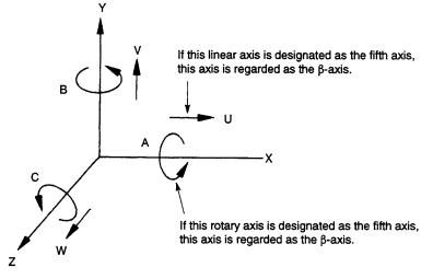
Fig. 1.1.1.1 Fourth Axis (a-axis) in the Right-hand Coordinate System
(c)Number of simultaneously controllable axes with the 5-axis control function*
The fifth axis can be selected optionally. In this manual, the fifth axis is referred to as “b- axis” and represents any of six axes – A, B, C, U, V, and W. Which address characters should be used for the fifth axis is set for parameterspm1112, pm1113, and pm1114, and pm1154, pm1155, and pm1156. The number of simultaneously controllable axes is indicated in Table 1.6.
1 - 4

YASNAC PCNC Programming Manual |
Chapter 1: Programming Basics |
|
|
Table 1.1.1.6: The Number of Simultaneously Controllable Axes with 5-axis Control Function
|
Number of Simultaneously Controllable Axes |
||
|
|
|
|
Positioning (G00) |
5 axes (X-. Y-, Z-, α -, and β -axis) |
|
|
|
|
|
|
Linear interpolation (G01) |
5 axes (X-. Y-, Z-, α -, and β -axis) |
|
|
|
|
||
|
2 axes (X- and Y-axis, Y- and Z-axis, or Z- and X-axis) |
||
Circular interpolation (G02, G03) |
2 axes (X- and a-axis, Y- and α -axis, or Z- and α -axis) |
||
|
2 axes (X- and b-axis, Y- and β -axis, or Z- and β -axis) |
||
|
|
|
|
*Circle cutting (G12, G13) |
2 axes (X- and Y-axis) |
|
|
|
|
|
|
|
2 axes (circular interpolation in XY plane)) |
Simultaneous |
|
*Helical interpolation (G02, G03) |
1 axis (linear interpolation, Z-axis) |
||
3-axis control |
|||
|
See 2.1.4, “Helical Interpolation (G02, G03)”. |
||
|
|
||
|
|
|
|
Manual operation |
5 axes (X-, Y-, Z-,and α -axis) |
|
|
|
|
|
|
Note 1: |
Circular interpolation is possible only when a- and b-axis are linear axes. The plane in which |
|
circular interpolation is executed is determined by the plane selection G code (G17 to G19) |
|
which is presently valid. For details, see 2.1.3, “Circular interpolation (G02, G03)”. |
2:With a manual pulse generator, simultaneous control is possible in either one or three axes.
For the b-axis, either a rotary axis or a linear axis can be selected.
•A rotary axis (A-, B-, or C-axis) is defined as indicated in Table 1.1.1.7.
Table 1.1.1.7: |
Rotary Axes |
|
|
|
|
|
Rotary Axis |
Definition |
|
|
|
|
A-axis |
Rotary axis around an axis which is parallel to X-axis |
|
|
|
|
B-axis |
Rotary axis around an axis which is parallel to Y-axis |
|
|
|
|
C-axis |
Rotary axis around an axis which is parallel to Z axis |
|
|
|
Note 1: |
The unit of output increment (motion increment) and input increment for a rotary axis is |
|
“degrees” instead of “mm” which is used for a linear axis (X-, Y-, Z-axis). With the exception |
|
of the unit, a rotary axis can be treated in the same manner as a linear axis. (Metric system) |
|
(The NC calculates feedrate assuming 0.001 deg. as 0.001mm.) |
2:Even if the dimensions are changed to inches by using the inch/mm selection function, the unit system for a rotary axis remains unchanged (degrees).
•A linear axis (U-, V-, or W-axis) is defined as indicated in Table 1.1.1.8.
Table 1.1.1.8: |
Linear Axes |
|
|
|
|
|
Linear Axis |
Definition |
|
|
|
|
U-axis |
A linear axis parallel to X-axis. |
|
|
|
|
V-axis |
A linear axis parallel to Y-axis. |
|
|
|
|
W-axis |
A linear axis parallel to Z-axis. |
|
|
|
1 - 5
YASNAC PCNC Programming Manual |
Chapter 1: Programming Basics |
|
|
|
|
Note 1: |
The unit of output increment (motion increment) and input increment of a linear axis is the |
|
|
same as other linear axes (X-, Y-, and Z-axis). The linear axes indicated above can be treated |
|
|
in exactly the same manner as other linear axes, |
|
2: |
When the inch system is selected by using inch/nm selection function, dimensions must be |
|
|
input in units of inches as with other axes (X-, Y-, and Z-axis). |
|
Fig. 1.1.1.2 Fifth Axis (b-axis) in the Right-hand Coordinate System
1.1.2Least Input Increment and Least Output Increment
The least input and output increments vary depending on the type of controlled axis whether it is a rotary axis or a linear axis.
(1)Least Input Increment
The least input increment to express axis movement distance that is input by using punched tape or manual data input switches is indicated in Tables 1.9, 1.10, and 1.11.
Table 1.1.2.1: Least Increment (Standard)
|
Linear Axis |
*Rotary Axes |
|
|
|
Metric Input |
0.001 mm |
0.001 deg. |
|
|
|
Inch Input |
0.0001 inch |
0.001 deg. |
|
|
|
Table 1.1.2.2: Least Increment (Sub Microns)
|
Linear Axis |
*Rotary Axes |
|
|
|
Metric Input |
0.0001 mm |
0.001 deg. |
|
|
|
Inch Input |
0.00001 inch |
0.001 deg. |
|
|
|
1 - 6
YASNAC PCNC Programming Manual |
|
Chapter 1: Programming Basics |
|||
|
|
|
|
|
|
Table 1.1.2.3: |
Least Increment (Sub Sub-microns) |
||||
|
|
|
|
|
|
|
|
|
Linear Axis |
*Rotary Axes |
|
|
|
|
|
|
|
|
Metric Input |
0.00001 mm |
0.001 deg. |
|
|
|
|
|
|
|
|
|
Inch Input |
0.000001 inch |
0.001 deg. |
|
|
|
|
|
|
|
|
Note: Selection of “mm-input” and “inch-input” is made by the setting parameter pm0007 D0.
(2)Least Output Increment
The least output increment indicates the “minimum unit” of axis movement that is determined by the mechanical system. By selecting the option, it is possible to select the output unit system between “mm” and “inches”.
Table 1.1.2.4: Least Output Unit (Standard)
|
Linear Axis |
*Rotary Axes |
|
|
|
Metric Output |
0.001 mm |
0.001 deg. |
|
|
|
Inch Output |
0.0001 inch |
0.001 deg. |
|
|
|
Table 1.1.2.5: Least Increment (Sub Microns)
|
Linear Axis |
*Rotary Axes |
|
|
|
Metric Output |
0.0001 mm |
0.001 deg. |
|
|
|
Inch Output |
0.00001 inch |
0.001 deg. |
|
|
|
Table 1.1.2.6: Least Increment (Sub Sub-microns)
|
Linear Axis |
*Rotary Axes |
|
|
|
Metric Output |
0.00001 mm |
0.001 deg. |
|
|
|
Inch Output |
0.000001 inch |
0.001 deg. |
|
|
|
1 - 7
YASNAC PCNC Programming Manual |
Chapter 1: Programming Basics |
|
|
1.1.3Maximum Programmable Values for Axis Movement
The maximum programmable values that can be designated for a move command are indicated in Tables 1.15, 1.16, and 1.17. The maximum programmable values indicated in these tables are applicable to addresses I, J, K, R, and Q which are used for designating “distance” in addition to the move command addresses X, Y, Z, a, and b.
Table 1.1.3.1: |
Maximum Programmable Values for Axis Movement (Standard) |
||||
|
|
|
|
|
|
|
|
|
Linear Axis |
*Rotary Axes |
|
|
|
|
|
|
|
|
Metric Output |
Metric Input |
±999999.999 mm |
±999999.999 deg. |
|
|
|
|
|
|
|
|
Inch Input |
±39370.0787 mm |
±999999.999 deg. |
|
|
|
|
|
|||
|
|
|
|
|
|
|
Inch Output |
Metric Input |
±999999.999 mm |
±999999.999 deg. |
|
|
|
|
|
|
|
|
Inch Input |
±999999.999 mm |
±999999.999 deg. |
|
|
|
|
|
|||
|
|
|
|
|
|
Table 1.1.3.2: Maximum Programmable Values for Axis Movement (Sub-microns)
|
|
Linear Axis |
*Rotary Axes |
|
|
|
|
|
|
Metric Output |
Metric Input |
±999999.999 mm |
±999999.999 deg. |
|
|
|
|
||
Inch Input |
±39370.0787 mm |
±999999.999 deg. |
||
|
||||
|
|
|
|
Table 1.1.3.3: Maximum Programmable Values for Axis Movement (Sub Sub-microns)
|
|
Linear Axis |
*Rotary Axes |
|
|
|
|
Metric Output |
Metric Input |
±999999.999 mm |
±999999.999 deg. |
|
|
|
|
Inch Output |
Inch Input |
±39370.0787 mm |
±999999.999 deg. |
|
|
|
|
In incremental programming, the values to be designated must not exceed the maximum programmable values indicated above. In absolute programming, the move distance of each axis must not exceed the maximum programmable values indicated above. In addition to the notes indicated above, it must also be taken into consideration that the cumulative values of move command must not exceed the values indicted in Tables 1.18, 1.19, and 1.20.
Table 1.1.3.4: Maximum Cumulative Values (Standard)
|
Linear Axis |
*Rotary Axes |
|
|
|
Metric Input |
±999999.999 mm |
±999999.999 deg. |
|
|
|
Inch Input |
±999999.999 inch |
±999999.999 deg. |
|
|
|
Table 1.1.3.5: Maximum Programmable Values for Axis Movement (Sub-microns)
|
Linear Axis |
*Rotary Axes |
|
|
|
Metric Input |
±999999.999 mm |
±999999.999 deg. |
|
|
|
1 - 8

YASNAC PCNC Programming Manual |
Chapter 1: Programming Basics |
|
|
Table 1.1.3.6: Maximum Programmable Values for Axis Movement (Sub Submicrons)
|
|
Linear Axis |
*Rotary Axes |
|
|
|
|
|
|
|
Metric Input |
±999999.999 mm |
±999999.999 deg. |
|
|
|
|
|
|
Note: |
The values indicated above do not depend on the “least output increment”. |
|||
(1)Programmable Range (Input Format)
This model of NC adopts the variable block format which complies with JIS B6313.
Programmable range of individual addresses is indicated in Table 1.1.3.7. The numbers given in this table indicate the allowable maximum number of digits.
An example of input format is given below.
Input data should be entered without a decimal point. If a decimal point is used, the entered values is treated in a different manner. Leading zeros and the “+” (plus) sign can be omitted for all kinds of address data including sequence number. Note that, however, the “-” (minus) sign cannot be omitted.
Table 1.1.3.7: |
Input Format (Standard) |
|
|
|
|
||||
|
|
|
|
|
|
|
|
||
Address |
|
Metric Output |
Inch Output |
B: Basic |
|||||
|
|
|
|
|
|
|
O: Option |
||
|
|
|
Metric Input |
|
Metric Input |
Metric Input |
|
Metric Input |
|
|
|
|
|
|
|
||||
|
|
|
|
|
|
|
|
|
|
Program number |
|
|
O5 |
|
O5 |
B |
|||
|
|
|
|
|
|
|
|||
Sequence number |
|
|
N5 |
|
N5 |
B |
|||
|
|
|
|
|
|
|
|||
G function |
|
|
G3 |
|
G3 |
B |
|||
|
|
|
|
|
|
|
|
|
|
Coordinate words |
Linear axis |
a+63 |
|
a+54 |
a+63 |
|
a+54 |
B |
|
|
|
|
|
|
|
|
|
|
|
Rotary axis |
b+63 |
|
b+63 |
b+63 |
|
b+63 |
O |
||
|
|
|
|||||||
|
|
|
|
|
|
|
|
|
|
Feed per minute (mm/min) |
|
F60 |
|
F41 |
F60 |
|
F51 |
B |
|
|
|
|
|
|
|
|
|
|
|
Feed per minute (mm/min) |
|
F61 |
|
F42 |
F61 |
|
F52 |
B |
|
1/10 function |
|
|
|
||||||
|
|
|
|
|
|
|
|
||
|
|
|
|
|
|
|
|
|
|
S function |
|
|
S 5 |
|
S5 |
B |
|||
|
|
|
|
|
|
|
|
||
T function |
|
|
T 2 |
|
T2 |
B |
|||
|
|
|
|
|
|
|
|
||
|
|
T 4 |
|
T4 |
O |
||||
|
|
|
|
|
|||||
|
|
|
|
|
|
|
|
|
|
1 - 9
YASNAC PCNC Programming Manual |
|
Chapter 1: Programming Basics |
|||
|
|
|
|
|
|
|
|
|
|
|
|
|
M function |
M 3 |
M3 |
B |
|
|
|
|
|
|
|
|
Tool offset number |
H4 or D4 |
H4 or D4 |
B |
|
|
|
|
|
|
|
|
B function |
B 3 |
B 3 |
O |
|
|
|
|
|
|
|
|
Dwell |
P 63 |
P 63 |
B |
|
|
|
|
|
|
|
|
Program number designation |
P 5 |
P 5 |
B |
|
|
|
|
|
|
|
|
Sequence number designation |
P 4 |
P 4 |
B |
|
|
|
|
|
|
|
|
Number of repetitions |
L 9 |
L 9 |
B |
|
|
|
|
|
|
|
Table 1.1.3.8: |
Input Format (Sub Microns) |
|
|
|
|
|||||||
|
|
|
|
|
|
|
|
|
|
|
||
|
|
Address |
Metric Output |
|
B: Basic |
|
||||||
|
|
|
|
|
|
|
O: Option |
|
||||
|
|
|
|
|
|
Metric Input |
|
Metric Input |
|
|
||
|
|
|
|
|
|
|
|
|
|
|||
|
|
|
|
|
|
|
|
|
|
|
||
|
Program number |
|
O5 |
|
|
B |
|
|||||
|
|
|
|
|
|
|
|
|
|
|||
|
Sequence number |
|
N5 |
|
|
B |
|
|||||
|
|
|
|
|
|
|
|
|
|
|
||
|
|
G function |
|
G3 |
|
|
B |
|
||||
|
|
|
|
|
|
|
|
|
|
|
|
|
|
Coordinate words |
Linear axis |
a+54 |
|
|
a+45 |
|
B |
|
|||
|
|
|
|
|
|
|
|
|
|
|||
|
Rotary axis |
b+54 |
|
|
b+54 |
|
O |
|
||||
|
|
|
|
|
|
|
|
|||||
|
|
|
|
|
|
|
|
|
|
|
|
|
|
Feed per minute (mm/min) |
F 51 |
|
|
F 32 |
|
B |
|
||||
|
|
|
|
|
|
|
|
|
|
|
||
|
Feed per minute (mm/min) |
F 52 |
|
|
F 33 |
|
B |
|
||||
|
1/10 function |
|
|
|
|
|||||||
|
|
|
|
|
|
|
|
|||||
|
|
|
|
|
|
|
|
|
|
|
|
|
|
|
S function |
|
S 5 |
|
|
B |
|
||||
|
|
|
|
|
|
|
|
|
|
|
|
|
|
|
T function |
|
T 2 |
|
|
B |
|
||||
|
|
|
|
|
|
|
|
|
||||
|
|
|
T 4 |
|
|
O |
|
|||||
|
|
|
|
|
|
|
|
|
|
|||
|
|
|
|
|
|
|
|
|
|
|
||
|
|
M function |
|
M 3 |
|
|
B |
|
||||
|
|
|
|
|
|
|
|
|
||||
|
Tool offset number |
|
H4 or D4 |
|
B |
|
||||||
|
|
|
|
|
|
|
|
|
|
|
||
|
|
B function |
|
B 3 |
|
|
O |
|
||||
|
|
|
|
|
|
|
|
|
|
|||
|
|
Dwell |
|
P 63 |
|
B |
|
|||||
|
|
|
|
|
|
|
|
|
|
|||
|
Program number designation |
|
P 5 |
|
|
B |
|
|||||
|
|
|
|
|
|
|
|
|
|
|||
|
Sequence number designation |
|
P 4 |
|
|
B |
|
|||||
|
|
|
|
|
|
|
|
|
|
|||
|
Number of repetitions |
|
L 9 |
|
|
B |
|
|||||
|
|
|
|
|
|
|
|
|
|
|
||
Table 1.1.3.9: |
Input Format (Sub Sub-microns) |
|
|
|
||||||||
|
|
|
|
|
|
|
|
|
|
|||
|
|
Address |
|
Metric Output |
|
B: Basic |
|
|||||
|
|
|
|
|
|
|
|
O: Option |
|
|||
|
|
|
|
|
|
Metric Input |
|
Metric Input |
|
|
||
|
|
|
|
|
|
|
|
|
|
|||
|
|
|
|
|
|
|
|
|
|
|||
|
Program number |
|
|
O5 |
|
|
B |
|
||||
|
|
|
|
|
|
|
|
|
||||
|
Sequence number |
|
|
N5 |
|
|
B |
|
||||
|
|
|
|
|
|
|
|
|
||||
|
G function |
|
|
G3 |
|
|
B |
|
||||
|
|
|
|
|
|
|
|
|
|
|
|
|
|
Coordinate words |
|
Linear axis |
|
a+45 |
|
|
a+36 |
|
B |
|
|
|
|
|
|
|
|
|
|
|
|
|||
|
|
Rotary axis |
|
b+45 |
|
|
b+45 |
|
O |
|
||
|
|
|
|
|
|
|
|
|
||||
|
|
|
|
|
|
|
|
|
|
|
||
|
Feed per minute (mm/min) |
|
F 42 |
|
|
F 23 |
|
B |
|
|||
|
|
|
|
|
|
|
|
|
|
|
|
|
1 - 10

YASNAC PCNC Programming Manual |
|
|
|
Chapter 1: Programming Basics |
|||
|
|
|
|
|
|
|
|
|
|
|
|
|
|
|
|
|
Feed per minute (mm/min) |
F 43 |
|
F 24 |
|
B |
|
|
1/10 function |
|
|
|
|||
|
|
|
|
|
|
|
|
|
|
|
|
|
|
|
|
|
S function |
|
S 5 |
|
B |
|
|
|
|
|
|
|
|
|
|
|
T function |
|
T 2 |
|
B |
|
|
|
|
|
|
|
|
|
|
|
|
T 4 |
|
O |
|
||
|
|
|
|
|
|||
|
|
|
|
|
|
|
|
|
M function |
|
M 3 |
|
B |
|
|
|
|
|
|
|
|
|
|
|
Tool offset number |
|
H4 or D4 |
|
B |
|
|
|
|
|
|
|
|
|
|
|
B function |
|
B 3 |
|
O |
|
|
|
|
|
|
|
|
|
|
|
Dwell |
|
P 63 |
|
B |
|
|
|
|
|
|
|
|
|
|
|
Program number designation |
|
P 5 |
|
B |
|
|
|
|
|
|
|
|
|
|
|
Sequence number designation |
|
P 4 |
|
B |
|
|
|
|
|
|
|
|
|
|
|
Number of repetitions |
|
L 9 |
|
B |
|
|
|
|
|
|
|
|
|
|
1.1.4Optional Block Skip (/1), (/2 to /9) *
If a block containing the slash code “/n (n = l to 9)” is executed with the external optional block skip switch corresponding to the designated number set ON, the commands in the block following the slash code to the end of block code are disregarded. The slash code “/n” can be designated at any position in a block.
Example:
/ 2 N 1234 G01X100 / 3 Y200;
If the “/2” switch is ON, the entire block is disregarded, and
if “/3” switch is ON, this block indicates the following.
N 1234 G01 X100;
1.“1” can be omitted for “1”.
2.The optional block skip function is processed when a part program is read to the buffer register from either the tape or memory. If the switch is set ON after the block containing the optional block skip code is read, the block is not skipped.
3.The optional block skip function is disregarded for program reading (input) and punch out (output) operation.
1 - 11
YASNAC PCNC Programming Manual |
Chapter 1: Programming Basics |
|
|
1.1.5Buffer Register and Multi-active Register
By using the buffer register and multi-active register, the NC ensures smooth control of the machine by reading the blocks of data into the buffer register.
(1)Buffer Register
In normal operation, two blocks of data are buffered to calculate the offset and other data that are necessary for the succeeding operation.
In the tool radius offset C mode (option), two blocks of data (a maximum of four blocks of data, if necessary) are buffered to calculate the offset data that are necessary for the succeeding operation. In both of the normal operation mode and tool radius offset C mode, the data capacity of one block is a maximum of 128 characters, including the EOB code.
(2)Multi-active Registers *
With a part program enclosed by M93 and M92, a maximum of seven blocks of data are buffered. If the time required for automatic operation of these seven buffered blocks is longer than the time required for the buffering and calculation of the offset data for the next seven blocks, the program can be executed continuously without a stop between blocks.
Table 1.1.5.1: M92 and M93 Codes
Linear Axis |
Definition |
|
|
M92 |
Multi-active registers OFF |
|
|
M93 |
Multi-active registers ON |
|
|
1 - 12

YASNAC PCNC Programming Manual |
Chapter 1: Programming Basics |
|
|
1.2 BASICS OF FEED FUNCTION
This section describes the feed function that specifies feedrate (distance per minute, distance per revolution) of a cutting tool.
1.2.1Rapid Traverse
Rapid traverse is used for positioning (G00) and manual rapid traverse (RAPID) operation. In the rapid traverse mode, each axis moves at the rapid traverse rate set for the individual axes; the rapid traverse rate is determined by the machine tool builder and set for the individual axes by using parameters. Since the axes move independently of each other, the axes reach the target point at different time. Therefore, the resultant tool paths are not a straight line generally.
The rapid traverse override function can adjust the set rapid traverse rate to F0, 25%, 50%, and 100% where F0 indicates a fixed feedrate set for parameter pm2447.
1. Rapid traverse rate is set in the following units for the individual axes.
Setting units of rapid traverse rate |
1 mm/min |
|
0.1 inch/min |
|
1 deg./min |
2.The upper limit of the rapid traverse rate is 240,000 mm/min. Since the most appropriate value is set conforming to the machine capability, refer to the manuals published by the machine tool builder for the rapid traverse rate of your machine.
1.2.2Cutting Feed (F Command)
The feedrate at which a cutting tool should be moved in the linear interpolation (G01) mode or circular interpolation (G02, G03) mode is designated using address character F.
•With a 6-digit numeral specified following address character F, feedrate of a cutting tool can be designated in units of “mm/min”.
•The feedrate specified using an F code can be multiplied by 1/10 by changing the setting for parameter pm2004 D0. The programmable feedrate range is indicated in Table 1.2.2.1
Table 1.2.2.1: |
Programmable Range of F Code |
|
|||
|
|
|
|
|
|
|
Normal Mode (pm2004 DO=O) |
F-command 1/10 Function (pm2004 DO = l) |
|||
Input System |
|
|
|
|
|
Format |
|
Programmable Range |
Format |
Programmable Range |
|
|
|
||||
|
|
(Feed per Minute) |
(Feed per Minute) |
||
|
|
|
|
||
|
|
|
|
|
|
Microns |
F60 |
|
F1.0-F 24000 mm/min |
F61 |
F0.1-F 24000.0 mm/min |
|
|
|
|
|
|
Sub Microns |
F51 |
|
F0.1-F 24000.0 mm/min |
F52 |
F0.01-F 24000.00 mm/min |
|
|
|
|
|
|
Sub Sub-microns |
F42 |
|
F0.01-F 2400.00 mm/min |
F43 |
F0.001-F 2400.000 mm/min |
|
|
|
|
|
|
Inches |
F41 |
|
F0.1-F 9448.8 inch/min |
F42 |
F0.01-F 9448.81 mm/min |
|
|
|
|
|
|
1 - 13
YASNAC PCNC Programming Manual |
Chapter 1: Programming Basics |
|
|
•The upper limit of feedrates indicated in Table 1.2.2.1 could be restricted by the servo system and the mechanical system. In this case, the allowable upper limit is set for parameter (pm2800) and if a feedrate command exceeding this limit value is specified, the feedrate is clamped at the set allowable upper limit.
•An F command specified in the simultaneous 2-axis linear interpolation mode or in the curricular interpolation mode represents the feedrate in the tangential direction.
Example of Programming
With the following program:
G91 (incremental programming)
G01 X40. Y30. F500;
Fig. 1.2.2.1 F command in Simultaneous 2-axis Control Linear Interpolation
Example of Programming
Fig. 1.2.2.2 F command in the Simultaneous 2-axis Control Circular Interpolation
1 - 14
YASNAC PCNC Programming Manual |
Chapter 1: Programming Basics |
|
|
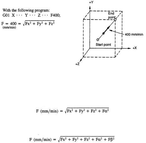
•In the simultaneous 3-axis control linear interpolation, an F command indicates the tangential feedrate.
Example of Programming
Fig. 1.2.2.3 F Command in Simultaneous 3-axis Control Linear Interpolation
•In the simultaneous 4-axis control* linear interpolation, an F command indicates the tangential feedrate.
•In the simultaneous 5-axis control* linear interpolation, an F command indicates the tangential feedrate.
1 - 15

YASNAC PCNC Programming Manual |
Chapter 1: Programming Basics |
|
|
1.The F-command 1/10 function does not influence the feedrate called by an F1-digit command.
2.After changing the setting for parameter pm2004 D0, the new setting becomes valid when the NC is reset.
3.During solid tapping, the F-command 1/10 function does not influence the feedrate called by an F command.
4.The feedrate specified by an E code in a canned cycle is influenced by the F-command 1/ 10 function. The command format of an E command is the same as with an F command.
5.When the F-command 1/10 function is used, the minimum unit of the system variables used for E and F commands is made one decimal place smaller. In metric input, if the least increment of the F command system variable is 1 mrn/min, for example, it becomes 0.1 mm/min when the F-command 1/ 10 function is used.
6.When the F-command 1/10 function is used, designation of the macro system variables of E and F commands and the arguments (E, F) used for calling a macro program requires entry of a decimal fraction increased by one digit. In metric input, the command of “G65 PI F1234”, for example, is expressed as “#9=123.4”.
7.If “F0” is specified, alarm “0370” occurs.
8.For an F command, a minus value must not be specified. If a minus value is specified for an F command, correct operation cannot be guaranteed.
1.2.3F1-Digit Feed*
It is possible to select a feedrate by specifying a l-digit numeral (1 to 9) following address F. With this manner of designation of an F command, the feedrate preset for the specified numeral is selected. The feedrate to be selected in response to the designation of F1 to F9 should be set for the parameters indicated in Table 1.2.3.1.
Table 1.2.3.1: |
Parameter Numbers Used for Presetting F1-digit Feedrates |
||
|
|
|
|
|
F Command |
Parameter Numbers |
|
|
|
|
|
|
F1 |
pm0820 |
|
|
|
|
|
|
F2 |
pm0821 |
|
|
|
|
|
|
F3 |
pm0822 |
|
|
|
|
|
|
F4 |
pm0823 |
|
|
|
|
|
|
F5 |
pm0824 |
|
|
|
|
|
|
F6 |
pm0825 |
|
|
|
|
|
|
F7 |
pm0826 |
|
|
|
|
|
|
F8 |
pm0827 |
|
|
|
|
|
|
F9 |
pm0828 |
|
|
|
|
|
Note: Value1= 0.1 mm/min, or 0.01 inch/min
1 - 16
YASNAC PCNC Programming Manual |
Chapter 1: Programming Basics |
|
|
When using the F1-digit feed function, it is possible to optimize the selected feedrate by turning the manual pulse generator while the F1-DIGIT switch is ON. Increase or decrease of increments per pulse (F1-digit multiply) should be set for the parameters indicated in Table 1.2.3.2.
Table 1.2.3.2: |
Parameter Numbers Used for Setting F1-digit Multiply for the para |
||
|
|
|
|
|
F Command |
Parameter Numbers |
|
|
|
|
|
|
F1 |
pm2111 |
|
|
|
|
|
|
F2 |
pm2112 |
|
|
|
|
|
|
F3 |
pm2113 |
|
|
|
|
|
|
F4 |
pm2114 |
|
|
|
|
|
|
F5 |
pm2115 |
|
|
|
|
|
|
F6 |
pm2116 |
|
|
|
|
|
|
F7 |
pm2117 |
|
|
|
|
|
|
F8 |
pm2118 |
|
|
|
|
|
|
F9 |
pm2119 |
|
|
|
|
|
Note: Value “1”= 0.1 mm/min per pulse
If increase/decrease increments per pulse is set for these parameters, the value set for the parameters in Table 1.31 is updated in response to the manual pulse generator operation.
Parameters indicated in Table 1.33 are used to set the upper limits of the feedrate for F1-digit feedrate selection. If a value larger than the allowable maximum feedrate set for parameter pm2800 is set, it is disregarded and replaced with the value set for pm2800.
Table 1.2.3.3: |
Parameters pm2865 and pm2866 |
|
|
|
|
Parameter Numbers |
Description |
|
|
|
|
pm2865 |
|
Allowable maximum feedrate for F1 to F4 |
|
|
|
pm2866 |
|
Allowable maximum feedrate for F5 to F9 |
|
|
|
1.When the 1-digit numerals are set to the parameters pm0802 to pm0828, and pm2004 D0 = 0, feedrate on the screen is displayed as “0”. However, the machine moves in units of 0.1 to 0.9mm/min or 0.01 to 0.09 inch/min.
pm2004 D0 = 0
Feedrate at the deceleration of 0.001mm or 0.0001 inch is F6.0 mm/min or F4.1 inch/min.
pm2004 D0 = 1
Feedrate at the deceleration of 0.001mm or 0.0001 inch is F6.1 mm/min or F4.2 inch/min.
2. If “F0”is specified, alarm “0370” occurs.
1 - 17
YASNAC PCNC Programming Manual |
Chapter 1: Programming Basics |
|
|
3.When the DRY RUN switch is ON, feed commands are all executed at the feedrate set for the dry run operation.
4.The feed override function is invalid for the feedrate selected by the F1-digit command.
5.The feedrate set for the parameter is retained in memory if the power is turned OFF.
6.It is possible to designate an F1-digit command by specifying a variable in a macro program.
7.With the inch specification, feedrates are set in units of inch/min. However, the allowable maximum feedrates can be set only in units of mm/min.
1.2.4Feed per Minute Function (G94)
When G94 is designated, a feedrate specified following address F is executed in units of “mm (inch)/min”.
1.2.5Solid Tap Mode (G93, G94) *
The following G codes are used to indicate that tapping should be executed by using the solid tap function.
Table 1.2.5.1: |
Solid Tap Mode G Codes |
|
||
|
|
|
|
|
|
G code |
|
Description |
Group |
|
|
|
|
|
|
G93 |
|
Solid tap mode |
05 |
|
|
|
|
|
|
G94 |
|
Solid tap mode cancel |
05 |
|
|
|
|
|
G93 and G94 are modal G codes. When the power is turned ON or when the NC is reset, the G94 mode is automatically set.
(1)Solid Tap Mode (G93)
In the G93 solid tap mode, solid tapping is executed for the tapping cycles called by G84 or G74. Axis feed is controlled in the “feed per revolution” mode. In the solid tap mode, only solid tapping is allowed and no other operation is possible.
(2)Solid Tap Mode Cancel (G94)
When G94 is executed, the solid tap mode is canceled. After the cancellation of the solid tap mode, conventional type tapping is executed in which axis feed is controlled in the “feed per minute” mode.
1 - 18
YASNAC PCNC Programming Manual |
Chapter 1: Programming Basics |
|
|
1.2.6Automatic Acceleration and Deceleration
Automatic acceleration/deceleration control is provided for rapid traverse and cutting feed operation, respectively.
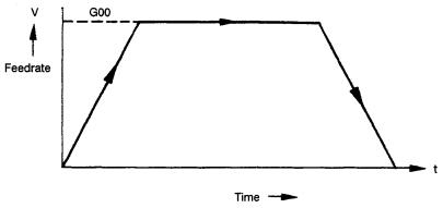
(1)Acceleration and Deceleration for Rapid Traverse and Manual Axis Feed Operation
For positioning (G00), manual rapid traverse (RAPID), manual continuous feed (JOG), and manual handle feed (HANDLE), linear pattern automatic acceleration/deceleration is applied. Rapid traverse rate and acceleration/deceleration time constant for rapid traverse are set for following parameters.
Table 1.2.6.1: |
Parameters Used for Setting Rapid Traverse Rate and Acceleration/ |
||||||
|
Deceleration Time Constant |
|
|
|
|
||
|
|
|
|
|
|
|
|
G code |
|
X-axis |
Y-axis |
Z-axis |
4th-axis |
5th-axis |
|
|
|
|
|
|
|
|
|
Rapid traverse rate |
|
pm2801 |
pm2802 |
pm2803 |
pm2804 |
m2805 |
|
|
|
|
|
|
|
|
|
Acceleration/deceleration time constant |
pm2461 |
pm2462 |
prn2463 |
pm2464 |
pm2465 |
|
|
|
|
|
|
|
|
|
|
Fig. 1.2.6.1 Automatic Acceleration/Deceleration in Linear Pattern
1 - 19
YASNAC PCNC Programming Manual |
Chapter 1: Programming Basics |
|
|
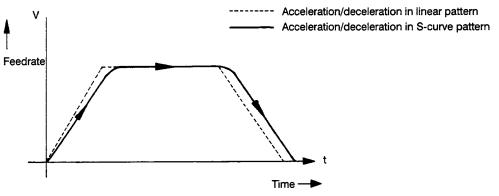
(2)Acceleration and Deceleration in S-curve Pattern *
For positioning operation (G00 mode positioning), S-curve pattern can be selected for the acceleration/deceleration pattern instead of the linear pattern. By using the S-curve pattern, positioning is possible at a high acceleration/deceleration rate without applying shock to the machine. The S-curve pattern for rapid traverse is defined by the following parameters.
Table 1.2.6.2: S-curve Pattern Defining Parameters (for Rapid Traverse)
Parameter |
Description |
Setting range |
|
|
|
pm2591 |
For rapid traverse of X-axis |
0 to 20 |
|
|
|
pm2592 |
For rapid traverse of Y-axis |
0 to 20 |
|
|
|
pm2593 |
For rapid traverse of Z-axis |
0 to 20 |
|
|
|
pm2594 |
For rapid traverse of 4th-axis |
0 to 20 |
|
|
|
pm2595 |
For rapid traverse of 5th-axis |
0 to 20 |
|
|
|
Fig. 1.2.6.2 Acceleration/Deceleration in S-curve Pattern
For the S-curve pattern acceleration/deceleration, time constant is provided for the individual axes and setting is possible in the range from 0 to 20.
Table 1.2.6.3: |
Time Constant for S-curve Pattern Control |
|
|
|
|
Setting Value |
Explanation |
|
|
|
|
0 |
Feedrate is controlled in the same pattern as acceleration/deceleration in |
|
the linear pattern. |
||
|
||
|
|
|
1 to 20 (N) |
The S-curve pattern having the time constant of “4 x N” is obtained. |
|
(Maximum time constant 60 msec) I |
||
|
||
|
|
|
Less than 0 |
Regarded as “0”. |
|
|
|
|
Greater than 20 |
Regarded as “20”. |
|
|
|
1 - 20

YASNAC PCNC Programming Manual |
Chapter 1: Programming Basics |
|
|
(3)Acceleration and Deceleration for Cutting Feed
For cutting feed (G01 to G03 mode), feedrate is controlled by the automatic acceleration/ deceleration in the exponential pattern.
Fig. 1.2.6.3 Acceleration/Deceleration in Exponential Pattern
Time constant for cutting feed and feedrate bias are set for parameters. For tapping, time constant and feedrate bias can be set independently.
Table 1.2.6.4: |
Parameters for Tapping |
|
|
|
|||
|
|
|
|
|
|
|
|
|
G code |
|
X-axis |
Y-axis |
Z-axis |
4th-axis |
5th-axis |
|
|
|
|
|
|
|
|
|
Feedrate time constant |
pm2501 |
pm2502 |
pm2503 |
pm2504 |
pm2505 |
|
|
|
|
|
|
|
|
|
|
Feedrate bias |
|
pm2821 |
pm2822 |
pm2823 |
pm2824 |
pm2825 |
|
|
|
|
|
|
|
|
|
Tapping time constant |
pm2511 |
pm2512 |
pm2513 |
pm2514 |
pm2515 |
|
|
|
|
|
|
|
|
|
|
Tapping feedrate bias |
pm2831 |
pm2832 |
pm2833 |
pm2834 |
pm2835 |
|
|
|
|
|
|
|
|
|
1.For the parameters indicated above, the most optimum values are set for respective machines. Do not attempt to change the setting unless necessary.
1 - 21
YASNAC PCNC Programming Manual |
Chapter 2: Commands Calling Axis Movements |
|
|
2
Commands Calling Axis Movements
Chapter 2 describes the interpolation commands and the reference point return commands.
2.1 INTERPOLATION COMMANDS . . . . . . . . . . . . . . . . . . . . . . . . . . . . . . . . . . . . . 2-2 2.1.1 Positioning (G00, G06, G60) . . . . . . . . . . . . . . . . . . . . . . . . . . . . . . . . . . . . 2-2 2.1.2 Linear Interpolation (G01) . . . . . . . . . . . . . . . . . . . . . . . . . . . . . . . . . . . . . . 2-4 2.1.3 Circular Interpolation (G02, G03) . . . . . . . . . . . . . . . . . . . . . . . . . . . . . . . . 2-5 2.1.4 Helical Interpolation (G02, G03)* . . . . . . . . . . . . . . . . . . . . . . . . . . . . . . . 2-11
2.2 REFERENCE POINT RETURN . . . . . . . . . . . . . . . . . . . . . . . . . . . . . . . . . . . . . . 2-13 2.2.1 Automatic Return to Reference Point (G28) . . . . . . . . . . . . . . . . . . . . . . . 2-13 2.2.2 Reference Point Return Check (G27) . . . . . . . . . . . . . . . . . . . . . . . . . . . . 2-17 2.2.3 Return from Reference Point Return (G29) . . . . . . . . . . . . . . . . . . . . . . . . 2-18 2.2.4 Second to Fourth Reference Point Return (G30) . . . . . . . . . . . . . . . . . . . . 2-22
2 - 1
YASNAC PCNC Programming Manual |
Chapter 2: Commands Calling Axis Movements |
|
|
2.1INTERPOLATION COMMANDS
This section describes the positioning commands and the interpolation commands that control the tool path along the specified functions such as straight line and arc.
2.1.1Positioning (G00, G06, G60)
In the absolute programming mode (G90), the axes are moved to the specified point in a workpiece coordinate system, and in the incremental programming mode (G91), the axes move by the specified distance from the present position at a rapid traverse rate.
For calling the positioning, the following G codes can be used,
Table 2.1.1.1 |
G Codes for Positioning |
|
||
|
|
|
|
|
|
G code |
|
Description |
Group |
|
|
|
|
|
|
G00 |
|
Positioning in the error detect ON mode |
01 |
|
|
|
|
|
|
G06 |
|
Positioning in the error detect OFF mode |
* |
|
|
|
|
|
|
G60 |
|
Unidirectional positioning |
01 |
|
|
|
|
|
(1)Positioning in the Error Detect ON Mode (G00)
When “G00X • • • Y • • • Z • • •;” is designated, positioning is executed in the “error detect ON” mode, in which the program advances to the next block only when the number of lag pulses due to servo lag are checked after the completion of pulse distribution has reduced to the permissible value.
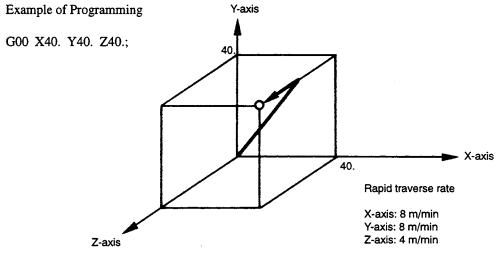
In the G00 mode, positioning is made at a rapid traverse rate in the simultaneous 3-axis (*5- axis) control mode. The axes not designated in the G00 block do not move. In positioning operation, the individual axes move independently of each other at a rapid traverse rate that is set for each axis. The rapid traverse rates set for the individual axes differ depending on the machine. For the rapid traverse rates of your machine, refer to the manuals published by the machine tool builder.
FIGURE 2.1.1.1 Positioning in Simultaneous 3-axis Control Mode
2 - 2
Loading...