


 Loading...
YASNAC PC NC
Maintenance Manual
Contents
Chapter 1: General Installation and Electrical Connection |
................... 1-1 |
|
1.1 |
Component Arrangement ............................................................ |
1-1 |
1.2 |
General Specifications ................................................................ |
1-5 |
Chapter 2: Routine Inspection ............................................................... |
2-1 |
|
2.1 |
Routine Inspection ...................................................................... |
2-1 |
2.2 Battery......................................................................................... |
2-1 |
|
2.3 |
Servo Motor ................................................................................ |
2-3 |
2.4 |
Fan .............................................................................................. |
2-4 |
2.5 |
Touch Screen .............................................................................. |
2-5 |
2.6 |
Control Panel .............................................................................. |
2-6 |
Chapter 3: Maintenance Instruments ..................................................... |
3-1 |
|
Chapter 4: Troubleshooting ................................................................... |
4-1 |
|
4.1 |
Maintenance Data ....................................................................... |
4-1 |
The VS-626M5 ..................................................................................... |
4-80 |
|
4.2 |
Notes For Safe Operation ......................................................... |
4-80 |
4.3 |
Receiving .................................................................................. |
4-86 |
4.4 |
Installation ................................................................................ |
4-90 |
4.5 |
Wiring ....................................................................................... |
4-93 |
4.6 |
Operation ................................................................................ |
4-128 |
4.7 |
Digital Operator ...................................................................... |
4-133 |
4.8 |
Maintenance And Inspection .................................................. |
4-147 |
4.9 |
Troubleshooting ...................................................................... |
4-149 |
Chapter 5: Adjustments ......................................................................... |
5-1 |
|
Chapter 6: Module/Unit Replacement ................................................... |
6-1 |
|
6.1 CPU Rack ................................................................................... |
6-1 |
|
6.2 |
CRT Display Unit ....................................................................... |
6-8 |
6.3 |
Floppy Disk Drive Unit ............................................................ |
6-17 |
6.4 |
NC Power Supply ..................................................................... |
6-18 |
6.5 |
Handheld Remote Machine Pendant......................................... |
6-19 |
6.6 Noise Filter ............................................................................... |
6-20 |
|
Chapter 7: Memory Option .................................................................... |
7-1 |
|
7.1 |
Part Numbers .............................................................................. |
7-1 |
7.2 |
RAM DIMM Installation ............................................................ |
7-1 |
Chapter 8: Fixed File Operations ............................................................ |
8-3 |
|
8.1 |
NC Data Handling ...................................................................... |
8-3 |
8.2 Yasnac PC NC CPU Rack BIOS Setup .................................... |
8-59 |
|
8.3 |
PLC Label in Diagnosis and Parameter Screens ...................... |
8-69 |
8.4 |
CNC Card Software Update ..................................................... |
8-72 |
8.5 |
Manual Page Customization ..................................................... |
8-82 |
8.6 |
Properties File Customization................................................... |
8-84 |
Chapter 1: General Installation and Electrical Connection |
PC NC Maintenance Manual |
|
|
Chapter 1: General Installation and
Electrical Connection
This section addresses the basic system: configuration, specifications, enclosure design, electrical connections, and installation.
1.1 Component Arrangement
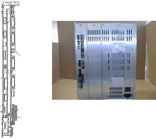
The YASNAC PC NC unit is composed of two boards: JCP20 and JFC20 (JZNC-JFC10). (Refer to the figure below.) The PC NC unit is inserted into a PC extended bus (ISA) inside the personal computer (PC) case. The I/O module, servo unit, spindle drive, and motor are the same as those of the YASNAC J100 CNC UNIT.
Figure 1.1: The YASNAC PC NC Unit
1-1
PC NC Maintenance Manual |
Chapter 1: General Installation and Electrical Connection |
|
|
FDD Mouse
PC NC case
PC
ISA bus
JFC10
DC +24V power
I/O Module
Monitor with Touch screen
Keyboard
Feeding servo unit
Spindle drive unit
High voltage
Machine
Feeding
motor
Spindle motor
Device on machine side
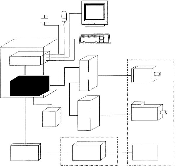
Figure 1.2: The YASNAC PC NC System Structure Diagram
1-2

Chapter 1: General Installation and Electrical Connection |
PC NC Maintenance Manual |
|
|
CPU R AC K UNIT |
Connection Between Devices |
|
|
|
|
|
||||
|
|
|
|
|
|
|
|
|
||
|
|
|
|
|
|
CRT |
|
|
|
|
|
|
|
|
|
|
|
KEYBO AR D |
|
|
|
|
|
HDD |
DA TA |
|
|
|
|
|
|
|
ATX |
|
PW R |
|
|
|
M O USE |
|
|
||
|
|
|
|
|
|
|
||||
|
|
|
|
|
|
|
|
|
||
M O THER |
|
|
|
|
|
|
|
TB3 |
|
|
BO ARD |
|
|
|
|
|
|
FDD |
|
|
|
|
|
|
|
|
DATA |
P W R |
|
|
||
|
ID E I/F |
|
|
|
|
|
|
|
|
|
|
K B D |
|
|
|
|
|
TS |
|
|
|
|
C OM 2 |
|
|
|
|
|
CO NTRO L |
TO UC H |
|
|
|
FD D |
|
|
|
|
|
|
|
|
|
|
|
|
|
|
|
|
|
SCREEN |
|
|
|
|
|
|
|
|
SE RVO O N |
|
|||
|
C OM 1 |
|
|
|
|
|
|
|||
|
|
|
|
|
|
|
|
|
|
|
PS/2 M O USE |
|
|
|
|
SH UT DO W N |
|
|
|||
|
|
|
|
|
|
|
|
|
||
|
LPT1 |
|
|
DC |
|
|
|
|
|
|
|
|
|
|
O UT |
|
|
|
|
|
|
|
VID EO |
|
|
24VDC FO R |
M ACH IN E |
|
|
|
||
|
|
|
M ACHINE I/O |
M AC HINE O P. PANEL I/O |
||||||
|
CARD |
|
|
|
CO NTRO L |
|||||
|
|
|
|
|
|
SIG NA LS |
|
|
|
|
PCI |
|
|
VIDEO |
|
CN1~6 I/O B OA RD |
CN14 |
CN5 |
|
|
|
|
|
|
|
I/O BO ARD CN1 |
HPG |
|||||
|
|
|
|
|
FO R M ACHINE SIG NAL |
|
||||
|
|
|
|
|
|
FO R M ACHINE |
|
|||
|
|
|
|
|
(FC 8X X) |
|
|
|
||
|
|
|
|
|
|
|
O P . PN L. |
|
||
|
|
|
|
|
CN11 |
|
|
|
|
|
|
|
|
|
|
|
|
|
(JS P02/04) |
|
|
|
|
|
|
|
|
|
|
|
|
|
|
|
|
|
|
CN13 |
|
CN12 |
CN3 |
CN7,8,9 |
|
|
JFC 20 |
|
|
|
|
|
||||
|
CN01 |
|
|
|
|
|
M A CHINE PANEL |
|||
|
|
|
|
S ENSO R SIG NAL |
|
|||||
|
|
|
CN02 |
|
|
|
SIG NALS |
|||
|
|
|
|
|
|
|
|
|
|
|
|
|
|
CN03 |
|
|
|
SERVO UNIT |
SG M G - |
||
|
|
|
CN04 |
|
|
SG D C -**AJA |
**A2AB* |
|||
ISA |
|
|
|
|
M |
|
||||
|
|
CN05 |
|
|
4C N |
|
3C N |
|
||
|
|
|
|
|
1C N |
|
|
|
|
|
|
|
|
|
|
|
Z AXIS |
|
|
||
|
|
|
|
|
|
52C N |
|
|
||
|
|
|
|
|
|
|
2C N |
PG |
|
|
|
|
|
|
|
|
51C N |
|
|
||
|
|
|
|
|
|
|
|
|
|
|
|
|
|
|
|
|
SG D C -**AJA |
M |
|
||
|
|
|
|
|
|
4C N |
|
3C N |
|
|
FAN 1 |
JCP20-1 |
|
|
|
1C N |
|
|
|
|
|
|
CN11 |
|
|
Y AXIS |
|
|
||||
|
|
|
|
|
52C N |
|
|
|||
|
|
|
CN12 |
|
|
|
2C N |
PG |
|
|
|
|
|
|
|
51C N |
|
|
|||
|
|
|
CN13 |
|
|
|
|
|
|
|
|
|
|
|
|
|
|
|
|
|
|
CPU |
|
|
CN14 |
|
|
SG D C -**AJA |
|
|
||
FAN |
|
|
|
|
M |
|
||||
|
|
|
|
|
|
4C N |
|
3C N |
|
|
|
|
|
|
|
|
1C N |
X AXIS |
|
|
|
|
|
|
|
|
|
52C N |
|
|
||
|
|
|
|
|
|
|
2C N |
PG |
|
|
|
|
|
|
|
|
51C N |
|
|
||
|
|
|
|
|
|
|
|
|
|
|
FA N3 |
|
CASE FAN |
|
|
INVERTER UNIT |
UAASK*-**FZ* |
||||
|
|
|
|
|
|
|
C1M R -M 5N |
|
FA |
|
|
|
|
|
|
|
4C N |
|
|
M |
|
|
|
PC PO W ER |
|
|
|
|
N |
|||
|
|
|
|
|
|
|
|
|||
|
|
|
|
1C N |
|
|
|
|
||
|
|
SUPPLY |
|
|
|
|
|
|
|
|
|
O UT |
O UT |
|
|
52C N |
|
|
|
|
|
|
|
|
PG S |
|
|
|
2C N |
PG |
|
|
|
|
INPUT |
(P OW ER |
|
|
51C N |
|
|
||
|
|
|
G O O D |
|
|
|
|
|
|
|
|
|
|
S IG NA L) |
|
|
|
|
|
|
|
|
|
|
|
|
C O NVERTER UNIT |
|
|
|||
|
|
|
|
|
|
C1M R -M R 5N |
|
|
||
|
|
|
|
|
|
|
|
|
REACTO R |
|
|
|
|
NC PO W ER |
|
5C N |
|
|
R /S/T |
X0100** |
|
|
|
|
SUPPLY |
|
|
|
|
|
|
|
|
|
|
INPU T O UTPU T |
|
|
|
|
A1/A2 |
|
|
|
|
|
|
|
|
|
|
|
|
|
|
|
|
|
INPUT PO W ER UNIT |
|
|
|
|
||
|
|
|
|
TB2 |
|
S VM |
|
|
|
|
|
|
|
|
TB1 |
|
|
|
|
|
|
|
|
|
|
NFB |
|
|
|
|
|
|
|
|
|
AC230V |
SVM |
|
A1/A2 |
|
|
|
|
Figure 1.3: Detail Connection of PC NC Unit With Various Devices.
1-3
PC NC Maintenance Manual |
Chapter 1: General Installation and Electrical Connection |
|
|
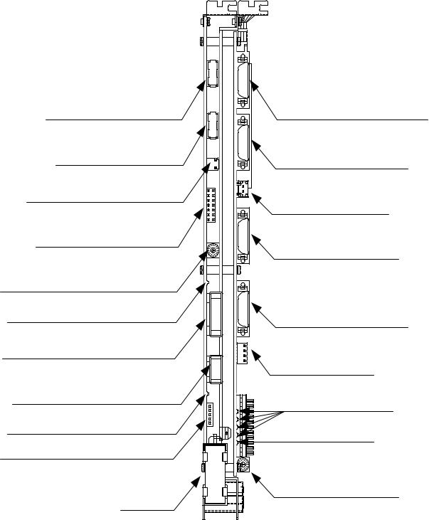
Connector Layout NC Side
The following figure provides a detailed Connectors Layout of the YAS-
NAC JZNC-JFC10 board.
Servo controller connector (CN01)
I/O module connector (CN02)
Power good signal connector (CN03)
Interruption setting short pin (S11)
Memory address setting rotary switch (S12)
I/O module power output verification LED
I/O module power output connector (CN04)
I/O module power input connector (CN05)
I/O module power input verification LED attery power reply supply connector (CN06)
Battery
|
Servo controller I/O connector (CN11) |
|
Power On/Off connector (CN12) |
|
Fuse (HM03, 0.3A) (F1) |
|
RS232C connector (CN14) |
|
Direct IN/OUT connector (CN14) |
|
System load switch (S1) |
|
System load switch (S1) |
|
(from top: 1, 2, 3, 4) |
|
Battery alarm LED |
LITHIUM |
System load rotary switch (S1) |
Figure 1.4: Detailed Layout of the YASNAC JZNC-JFC10 Board
1-4
Chapter 1: General Installation and Electrical Connection |
PC NC Maintenance Manual |
|
|
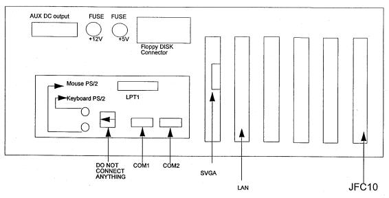
Connector Layout (PC Side)
Figure 1.5: Connector Layout of the PC NC CPU Rack (top view)
1.2 General Specifications
The enclosure must be designed to meet all of the following conditions.
Table 1.1: Specifications
Item |
|
Specifications |
|
|||
|
|
|
|
|
|
|
Ambient Conditions |
|
Temperature* |
Storage and |
-15oC to +65oC |
|
|
|
|
|
|
Transportation |
|
|
|
|
|
|
Operating |
PC NC unit |
0oC to +53oC |
|
|
|
|
(around |
I/O module |
|
|
|
|
|
enclosure) |
Servo Amplifier |
|
|
|
|
|
|
14” Color monitor with touch |
|
|
|
|
|
|
screen |
|
|
|
|
|
|
|
|
|
|
Humidity |
|
20% to 80% RH (with operation) |
|
|
|
|
|
|
|
10% to 90% RH (with non-operation) |
|
|
|
|
|
|
||
|
|
Vibration during operation |
Less than 4.9m/s |
|
||
|
|
|
|
|||
|
|
Others |
Free from dust, coolant, or organic solvent |
|||
|
|
|
|
|
||
|
|
PC NC Unit input power supply |
+24VDC+10% 180V-264VAC |
|
||
|
|
|
|
|||
|
|
Power Supply Unit |
Input power supply voltage: 180V ~ 264VAC |
|||
|
|
UPS000004 |
Frequency: 47Hz to 63Hz |
|
||
|
|
|
|
|
Momentary interruption: 0.5 cycle (0VDC) |
|
|
|
|
|
|
|
|
Note: |
Avoid installing the control panel in a location subject to direct sunlight, near heat generating |
|||||
1-5
PC NC Maintenance Manual |
Chapter 1: General Installation and Electrical Connection |
|
|
devices, or outdoors, even if the ambient temperature is within the specified range.
Design of the enclosure should be made on the basis that the average temperature increase of air within the enclosure (containing the PC NC unit and other compo-
nents) should be 10oC below the external air temperature.
(1) Temperature Increase within the Enclosure (Average Temperature Increase)
The internal temperature increase (sheet metal enclosure) is generally as follows: where,
∆Τ: Internal temperature increase (oC)
P:Heat generation in enclosure (W)
qe: |
Enclosure heat percolation ratio (W/oC) |
k: |
Heat transit ratio of sheet metal (W/m2oC) |
6W/m2oC: With internal cooling fan |
|
4W/m2oC: Without internal cooling fan |
|
A: |
Efficient heat diffusion area of enclosure (m2) |
Area capable of diffusing heat in surface area of the enclosure (Excluding area contacting other devices)
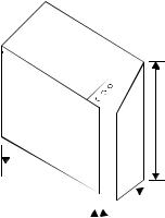
Example: Allowable heat generation in the enclosure with internal circulating fan
1200
All dimensions in millimeters |
800 |
|
|
||
700 |
Figure 1.6: Enclosure Dimensions
Efficient heat diffusion area is independently located, so bottom area is excluded.
A=4.16m2.
If the heat generation in the enclosure is supposed to be 246W (113W in the
1-6

Chapter 1: General Installation and Electrical Connection |
PC NC Maintenance Manual |
|
|
CNC portion, 104W in the servo portion, and 29W in the I/O portion):
∆Τ= |
|
P |
P |
|
|||
|
|
|
= |
k.A |
|
|
|
|
qe |
|
|||||
|
246 |
|
o |
||||
|
|
6 |
|
|
= 9.9 ( C) |
||
|
|
x 4.16 |
|||||
Therefore, the above value is within the temperature increase value.
When it exceeds 10oC, separate cooling countermeasures must be arranged.
(2) Heat Exchanger Cooling Capacity
Yaskawa can provide heat exchangers where the cooling capacity is insufficient even with a circulating fan mounted in the enclosure.
Table 1.2: Heat Exchangers
Heat Exchanger |
Cooling Capacity |
External Dimensions (mm) |
|
|
|
REX1550 |
100W /10oC |
295 width x 890 height x 50 depth |
HEATEX02 |
250W /10oC |
440 width x 924 height x 50 depth |
The heat generation indicated in the above table is the allowable heat generated when the internal temperature increase in the enclosure is limited to under 10oC.
1-7
PC NC Maintenance Manual |
Chapter 1: General Installation and Electrical Connection |
|
|
Example: Allowable Heat Generated in the Enclosure with Heat Exchanger
The amount of internal heat generated to make the internal temperature under 10oC when the enclosure is equipped with a HEATEX02 Heat Exchanger is expressed by the following equation:
P= k.A.∆Τ+ 250 W/10 oC
=6 x 4.16 x 10 + 250
=499 W/10 oC
Therefore, the amount of internal heat generated must be less than 499W.
(3)Mounting Heat Exchanger
The heat exchanger must be mounted on the enclosure provided by the machine tool builder, as shown in the figure below. Mount the exchanger so that the internal air is drawn from the upper portion and discharged through the lower portion, while the external air is drawn in from the lower portion and discharged through the upper portion.
Internal air |
Enclosure |
External air |

 Heat exchanger
Figure 1.7: Mounting of Heat Exchanger on the Machine Builder’s Enclosure
1-8

Chapter 1: General Installation and Electrical Connection PC NC Maintenance Manual
(4) Heat Generation by Respective Units
Table 1.3: Heat Generation
|
|
Total Heat |
Internal Heat |
Minimum Wind |
|
Unit |
Type |
Velocity for |
|||
Generation (W) |
Generation (W) |
||||
|
|
Cooling |
|||
|
|
|
|
||
|
|
|
|
|
|
PC NC rack |
JZNC-JPCRKM_-_ |
— |
— |
— |
|
|
|
|
|
|
|
14” Color CRT with |
JZNC-JPCOP-_ _ _ |
— |
— |
— |
|
Touchscreen |
|
|
|
|
|
|
|
|
|
|
|
I/O Module |
JANCD-FC810* |
29 |
29 |
0 |
|
|
|
|
|
|
|
|
JANCD-FC860* |
29 |
29 |
0 |
|
|
|
|
|
|
|
|
JANCD-FC861* |
14.5 |
14.5 |
0 |
|
|
|
|
|
|
|
Converter |
CIMR-MR5N23P7 |
84 |
44 |
2.5 |
|
|
|
|
|
|
|
|
CIMR-MR5N25P5 |
84 |
44 |
|
|
|
|
|
|
|
|
|
CIMR-MR5N27P5 |
119 |
61 |
|
|
|
|
|
|
|
|
|
CIMR-MR5N2011 |
152 |
70 |
|
|
|
|
|
|
|
|
|
CIMR-MR5N2015 |
204 |
88 |
|
|
|
|
|
|
|
|
|
CIMR-MR5N2018 |
273 |
108 |
|
|
|
|
|
|
|
|
|
CIMR-MR5N2022 |
335 |
132 |
|
|
|
|
|
|
|
|
|
CIMR-MR5N2030 |
392 |
160 |
|
|
|
|
|
|
|
|
Spindle Inverter |
CIMR-MR5N23P7 |
84 |
44 |
2.5 |
|
|
|
|
|
|
|
|
CIMR-MR5N25P5 |
185 |
58 |
|
|
|
|
|
|
|
|
|
CIMR-MR5N27P5 |
244 |
77 |
|
|
|
|
|
|
|
|
|
CIMR-MR5N2011 |
307 |
89 |
|
|
|
|
|
|
|
|
|
CIMR-MR5N2015 |
454 |
119 |
|
|
|
|
|
|
|
|
|
CIMR-MR5N2018 |
565 |
144 |
|
|
|
|
|
|
|
|
|
CIMR-MR5N2022 |
717 |
180 |
|
|
|
|
|
|
|
|
|
CIMR-MR5N2030 |
869 |
219 |
|
|
|
|
|
|
|
|
Reactor |
UZBA-B 20A 0.53 mH |
35 |
35 |
0 |
|
|
|
|
|
|
|
|
UZBA-B 30A 0.35 mH |
45 |
45 |
0 |
|
|
|
|
|
|
|
|
UZBA-B 40A 0.265 mH |
50 |
50 |
0 |
|
|
|
|
|
|
|
|
UZBA-B 60A 0.18 mH |
65 |
65 |
0 |
|
|
|
|
|
|
|
|
UZBA-B 80A 0.13 mH |
75 |
75 |
0 |
|
|
|
|
|
|
|
|
UZBA-B 90A 0.12 mH |
90 |
90 |
0 |
|
|
|
|
|
|
|
|
UZBA-B 120A 0.09 mH |
90 |
90 |
0 |
|
|
|
|
|
|
|
|
UZBA-B 160A 0.07 mH |
100 |
100 |
0 |
|
|
|
|
|
|
1-9

PC NC Maintenance Manual Chapter 1: General Installation and Electrical Connection
Table 1.3: Heat Generation (Continued)
|
|
Total Heat |
Internal Heat |
Minimum Wind |
|
Unit |
Type |
Velocity for |
|||
Generation (W) |
Generation (W) |
||||
|
|
Cooling |
|||
|
|
|
|
||
|
|
|
|
|
|
|
SGDC-05AJ A |
28 |
10 |
2.5 |
|
|
|
|
|
|
|
|
SGDC-10AJ A |
48 |
12 |
|
|
|
|
|
|
|
|
Servo Unit |
SGDC-15AJ A |
73 |
15 |
|
|
|
|
|
|
||
SGDC-20AJ A |
108 |
18 |
|
||
|
|
||||
|
|
|
|
|
|
|
SGDC-30AJ A |
148 |
22 |
|
|
|
|
|
|
|
|
|
SGDC-50AJ A |
208 |
28 |
|
|
|
|
|
|
|
1.The heat generated by the CNC unit varies depending on the addition of options. The heat generated by the I/O module varies with I/O status.
2.Internal heat generation is the heat remaining inside of the enclosure when the fin of the servo is exposed outside of the enclosure, and when the external air is applied to the fin at greater than 2.5m/s
3.The thermal design of the enclosure to house the servo unit varies with machine specifications, but is acknowledged to use a value of 70% of the load factor.
1-10
Chapter 2: Routine Inspection |
PC NC Maintenance Manual |
|
|
Chapter 2: Routine Inspection
This chapter includes the requirements to maintain optimum operating conditions over time.
2.1 Routine Inspection
The table below details routine inspection of the PC NC.
Table 2.1: Routine Inspection
Area |
Inspect Item |
Frequency |
System |
Remarks |
|
OFF/ON* |
|||||
|
|
|
|
||
|
|
|
|
|
|
Battery |
Verify battery alarm |
At power on |
ON |
If alarm LED is on, replace battery. |
|
|
LED is on. |
|
|
|
|
|
|
|
|
|
|
Servo motor |
Vibration and noise |
Daily |
ON |
Feel by hand; listen by ear. |
|
|
|
|
|
|
|
|
Motor contamina- |
Daily (or as |
ON and OFF |
Visual inspection |
|
|
tion and damage |
required) |
|
|
|
|
|
|
|
|
|
Fan |
Air flow |
Monthly |
ON and OFF |
Feel by hand; listen by ear. |
|
|
|
|
|
|
|
Touch screen |
Clean |
Daily |
ON and OFF |
Use clean rag. |
|
|
|
|
|
|
|
|
Calibrate |
Monthly |
ON |
Use Calibration Screen. |
|
|
|
|
|
|
|
Control panel |
Verify doors are |
Daily |
OFF |
Visual inspection |
|
|
tightly closed. |
|
|
|
|
|
|
|
|
|
|
|
Verify tight fit, no |
Monthly |
OFF |
Visual inspection |
|
|
gaps in the side |
|
|
|
|
|
plates, and door |
|
|
|
|
|
gaskets are not |
|
|
|
|
|
worn. |
|
|
|
|
|
|
|
|
|
*With the exception of inspections made while the NC is in the energized state (i.e., external cleanliness, vibration, noise, etc.), turn off the source power supply to the NC before undertaking routine maintenance service. To remove power completely from the NC, turn off the main circuit breaker on the power panel of the machine.
2.2Battery
To determine whether the battery must be replaced, and replacement directions, follow the steps below.
1. Press the Power OFF button.
2-1
PC NC Maintenance Manual |
Chapter 2: Routine Inspection |
|
|
2.Turn OFF the door interlock switch, if provided. (The power can be turned ON with the door open.)
3.Open the door to view the NC rack.
4.Turn the power ON. If the Battery Alarm LED is displayed in the Message Bar on the top portion of the screen, the battery must be replaced within 16 hours. Do not use commercially-available batteries. Contact a Yaskawa customer service representative.
5.If the battery must be replaced, turn the power OFF. Remove the battery from the battery holder.
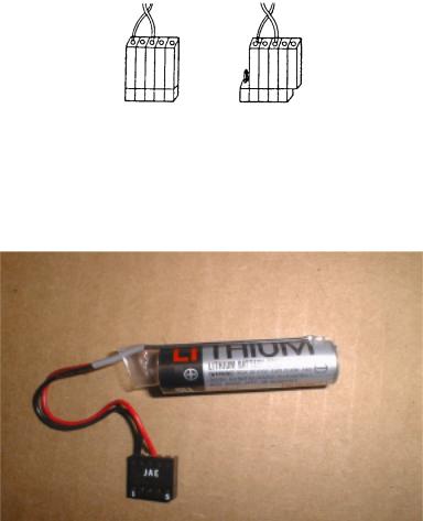
6.Place the new battery in the holder and set the connector. (Note: the direction of the connector is unimportant; however, poor connection may result in a lack of conduction.). Refer to the figure below.
Correct |
Correct |
Incorrect |
Figure 2.1: Battery Connection
Figure 2.2: Replacement Battery
2-2
Chapter 2: Routine Inspection |
PC NC Maintenance Manual |
|
|
Note: • Replace the battery as soon as possible after the power goes OFF to avoid data loss.
•Do not turn the power ON and OFF in rapid sequence.
•Wait 4 to 5 seconds after the power has been turned ON before turning the power OFF.
7.With the power ON, ensure that the “Message Alarm” display on the CRT and the red LED at the front of the JZNC-JFC10 PCB is OFF.
Note: If the “Message Alarm” display on the CRT or the red LED on the front are still illuminated, the probable cause is improper battery connection, or a defective battery.
When alarms 2121 or higher (encoder battery errors) occur, DGN #35024 (*BALM) is not output. When DGN #35024 (*BALM) is output, the LED goes on only when the CMOS backup battery is exhausted. This battery differs from the encoder batter.
2.3 Servo Motor
Inspect the servo motor daily as follows.
Table 2.2: Servo Motor Inspection
Inspect Item |
Remarks |
|
|
Vibration and noise |
Vibration can be checked by resting the hand on the motor. |
|
Noise can be checked by using a listening stick. Contact mainte- |
|
nance personnel immediately when any abnormality is found. |
|
|
Motor contamination and damage |
Visually check the motor exterior. If dirt or damage are |
|
observed, inspect the motor by removing the machine cover. |
|
Refer to the machine manufacturer’s manual. |
|
|
2-3
PC NC Maintenance Manual |
Chapter 2: Routine Inspection |
|
|
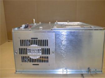
2.4 Fan
Verify the CPU rack cooling fan is running by placing a hand on the outside case in the path of the airflow.
Figure 2.3: CPU Rack and Fan
If the cooling fan speed falls below 2000rpm, a “Slow Fan” warning message appears. When this occurs, open the CPU rack and check the fan for any obstacles that may inhibit the fan rotation. If no obstacles are present, call a Yaskawa customer service representative.
If the CPU rack cooling fan speed falls below 1800rpm, a “Fan Alarm of CNC Unit” message appears. When this occurs, Cycle Start is not possible. Open the CPU rack and check the fan for any obstacles that may inhibit the fan rotation. If no obstacles are present, call a Yaskawa customer service representative.
2-4

Chapter 2: Routine Inspection |
PC NC Maintenance Manual |
|
|
2.5 Touch Screen
Clean the touch screen daily. Select PC Settings from the Utilities Menu. Select the Touch Screen Cleaning button. When the screen below appears, proceed to clean the touch screen.
1.Ensure there are no metal or other hard particles on the touch screen that may scratch the screen.
2.Use a general purpose liquid glass cleaner and a clean rag.
3.Never spray glass cleaner directly onto the touch screen. Always spray onto the clean rag.
4.Wipe the touch screen completely.
5.When finished, press the Escape key.
2-5
PC NC Maintenance Manual |
Chapter 2: Routine Inspection |
|
|
2.6 Control Panel
Details of the standard cabinet are explained below. Questions on customized cabinets should be referred to the manual issued by the machine manufacturer.
Follow the steps below for routine daily maintenance of the control panel.
1.Inspect the door(s) daily to ensure tight closure. The control panel is constructed as a dust-proof, sheet-steel enclosure with gasketed doors to keep out dust and oil mists. Keep the door(s) tightly closed at all times.
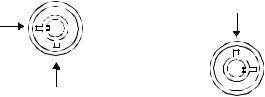
2.Following inspection of the control with the door open, close the door and fasten the door locks (two per door) securely using the key provided (Number YE001). When opening (counter-clockwise rotation) or closing (clockwise rotation), insert the key all the way into the keyhole and turn until it clicks (approximately a quarter-turn). The key can be removed from an open or closed position.
Left-hand Hinge Door |
Right-hand Hinged Door |
open position
closed position
 closed position
open position
Figure 2.4: Open and Closed Positions
Note: If the optional door interlocking switch is provided, opening the door shuts off the main power supply and stops all operations.
The following monthly maintenance must be performed.
1.Inspect the gaskets on the rims of the front and rear doors for openings or damage.
2.Inspect the inside of the enclosure; clean it if necessary.
3.Look for any opening in the door base when the doors are tightly shut.
2-6

Chapter 3: Maintenance Instruments |
PC NC Maintenance Manual |
|
|
Chapter 3: Maintenance Instruments
Measuring instruments, tools, and replacement parts are described in this chapter.
Table 3.1: Measuring Instruments
Name |
Allowable Measuring |
Purpose |
|
Range |
|||
|
|
||
|
|
|
|
Tester |
10 to 33VAC (at 40 to 100Hz) |
To measure AC power voltages |
|
|
Tolerance: ±2% |
|
|
|
|
|
|
|
Several mV to 100VDC |
To measure DC power voltages |
|
|
Tolerance: ±2% |
|
|
or multi-purpose digital meter |
|
|
|
Up to multiples of 10MΩ |
To measure currents |
||
|
|
|
The only required tools are those listed below.
•Phillips screwdrivers (large, medium, and small)
•Standard screwdrivers (medium and small)
•ROM extractor: IC extractor model GX-6
3-1
PC NC Maintenance Manual |
Chapter 3: Maintenance Instruments |
|
|
Maintenance/replacement parts are:
•Fuse model HMO3, 0.3A; approximate mass: 0.4g
•NC card fuse
•CPU rack fuse: 1A 250V 3AG fast-acting type glass body cartridge fuse; or 250V 3AG fast-acting type glass body cartridge fuse
Note: The current CPU rack fuse is 1A Littlefuse #312001, but will change to 3A Littlefuse #312003 fuse per ECO #N-9910-020.
•Motherboard battery: coin-type 3V lithium battery, part # Mitsubishi #CR2032, or Maxell #CR2032
3-2

Chapter 4: Troubleshooting |
PC NC Maintenance Manual |
|
|
Chapter 4: Troubleshooting
4.1 Maintenance Data
To locate the cause of problems or when contacting your Yaskawa customer service representative for advice, users must precisely understand the actual situation. To minimize the downtime, check the following points carefully.
CAUTION
•When an alarm occurs, eliminate the fault and assure operation safety before resetting it. Failure to observe this caution could result in equipment malfunction.
•For details on the machine-related sequence, refer to the machine tool manual.
Checking the Status of Problems
(1) Understanding the Situation
To identify the nature of the problem, first check the following items.
•Type of operation that causes a problem.
Do other types of operations not cause problems?
•Q Details of problems
How, frequency (always or sometimes), and when?
•Unusual situation when the problem occurred.
•Was there an unusual external occurrence (such as power failure or lightning) when the problem occurred?
•Timing of problem occurrence.
Did the problem occur during or after the operation of the keys, or in a specific operation mode?
(2)Check Items
(a)Problems related with axis feed and spindle drive Check the following items.
•Indication status of the LEDs on the drive unit
•Fuses and breakers
4-1
PC NC Maintenance Manual |
Chapter 4: Troubleshooting |
|
|
•Timing of problem occurrence – when the power is turned ON, during acceleration, during deceleration or during fixed speed spindle rotation, etc.?
(b)Problems related to part program
Record the program block data, offset data, workpiece coordinate system offset data, coordinate system setting data, etc.
Checking the NC Information
Aside from the specific problem, the following information must be obtained regarding the hardware environment.
•Machine tool builder’s name
•Delivery date of machine tool
•Type and model name of the machine tool
•Type and model name of the NC and units
Example
NC unit |
YASNAC PC NC |
|
|
Servo drive |
SGDC-AJA |
|
|
Servo motor |
SGMG |
|
|
Spindle drive |
CIMR-M5N20155 |
|
|
Spindle motor |
UAASKD-11HB11 |
|
|
Display of Alarm Information
If an alarm occurs, the top priority alarm number and alarm comment are displayed in the normal display area disregarding the selected mode and the screen.
4-2
Chapter 4: Troubleshooting |
PC NC Maintenance Manual |
|
|
Cause of Alarm and Corrective Action
The following shows the listing of YASNAC PC NC alarms.
Table 4.1: Alarm Numbers and Classification
Number |
Contents |
Stop Mode |
Output |
How To Reset |
|
|
|
|
|
0000 to |
Errors related to edit and operation |
Block stop |
Input error |
Reset |
0049 |
Occurring in the background mode |
|
alarm |
|
|
also. |
|
|
|
|
|
|
|
|
0050 to |
Errors related to edit and operation |
Block stop |
Input error |
Reset |
0099 |
Not occurring in the background |
|
alarm |
Power OFF for #0050 and #0051 |
|
mode. |
|
|
|
|
|
|
|
|
0100 to |
Program error |
Block stop |
Input error |
Reset |
0499 |
|
|
alarm |
|
|
|
|
|
|
1000 to |
Program error |
Block stop |
Input error |
Reset |
1099 |
DNC, COMS total, etc. |
|
alarm |
|
|
|
|
|
|
2000 to |
Machine related error |
Stop after |
Alarm |
Reset operation after removing the |
2199 |
OT, reference point return, machine |
deceleration, |
|
cause. With the alarm caused by |
|
ready, in-position, etc. |
or immediate |
|
the machine ready signal, if it |
|
|
stop |
|
occurs in the first power ON opera- |
|
|
|
|
tion, it is automatically reset. |
|
|
|
|
|
3000 to |
Servo and spindle related alarm |
Immediate |
Alarm |
Reset after removing the cause. |
3299 |
ESP, CPU mutual monitoring |
stop, or serve, |
|
With the SVOFF alarm, it is auto- |
|
|
OFF |
|
matically reset by the SVON. |
|
|
|
|
|
8000 to |
Memory check error |
Immediate |
Alarm |
For maintenance |
8049 |
Watchdog timer error |
stop, or serve |
|
CPU halt |
|
Offline error |
OFF |
|
Switching to the maintenance |
|
|
|
|
screen |
|
|
|
|
|
9000 to |
Error occurring in background edit- |
Not stopped |
Back- |
Reset or with reset soft-key |
9049 |
ing (basically the same as with 0000 |
|
ground |
|
|
to 0049) |
|
error |
|
|
|
|
output |
|
|
|
|
|
|
No number |
Battery error |
Not stopped |
No output |
Changing the battery |
indication |
Encoder alarm |
|
|
|
BAT |
|
|
|
|
indication |
|
|
|
|
BAT, AXIS |
|
|
|
|
|
|
|
|
|
No number |
Key operation error, edit operation |
Not stopped |
Warning |
Next key operation |
indication |
error (not serious operation error) |
|
|
|
Warning |
|
|
|
|
message |
|
|
|
|
|
|
|
|
|
4-3
PC NC Maintenance Manual |
Chapter 4: Troubleshooting |
|
|
Troubleshooting (1)
(1)Alarm Number 1099 (High Temperature)
Table 4.2: Countermeasures - Alarm #1099 (High Temperature)
Cause |
Check Item |
Countermeasures |
|
|
|
Ambient temperature of the |
Open the NC unit door to check |
If the fan is faulty, it must be |
NC rack exceeded the |
whether the cooling fan is operating |
replaced. Contact your Yaskawa |
specified value* due to the |
correctly. |
customer service representative. |
failure of the cooling fan. |
• Ensure that air is blowing out |
If the cooling duct is blocked, |
* 70ºC ± 3ºC when mea- |
through the ventilation port of |
remove the interfering object and |
sured above CPS-18. |
the cooling duct. |
start the cooling fan. |
|
• Ensure that the ventilation port |
|
|
of the cooling duct is not |
|
|
blocked. |
|
|
|
|
Internal temperature of the |
Allow the power supply unit to cool |
The power supply unit must be |
power supply unit is high. |
by turning OFF the power with the |
changed. Contact your Yaskawa |
|
PC NC unit door opened. If the |
customer service representative. |
|
alarm occurs even after the power |
|
|
supply unit has been cooled for 30 |
|
|
minutes, the power supply unit is |
|
|
faulty. |
|
|
|
|
Ambient temperature of the |
Measure the ambient temperature. |
This is not the failure of the NC |
l NC unit is high.* |
• If the NC unit is placed in direct |
unit. Remove the cause. |
*: Allowable temperature |
sunlight, the NC unit tempera- |
|
range for operation is |
ture may exceed the allowable |
|
0 to 40ºC. |
limit. |
|
|
|
|
4-4
Chapter 4: Troubleshooting |
PC NC Maintenance Manual |
|
|
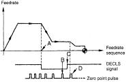
(2)Alarm Numbers 2061 to 2068 (Reference Point Return Area Error)
Table 4.3: Troubleshooting - Alarm #2061 ~ 2068 (Reference Point Return Area Error)
Cause |
|
|
Check Item |
Countermeasures |
||
|
|
|
||||
The reference |
Deceleration limit switch (DECLS) |
Return the axis to a position on |
||||
point return start |
#3073 DO (1st axis) |
Execute reference |
the deceleration LS or away |
|||
point is at the |
from it and, then execute refer- |
|||||
#3073 D1 |
(2nd. axis) |
point return again |
||||
zero point side |
ence point return once again. |
|||||
#3073 D2 |
(3rd axis) |
while observing the |
||||
of the decelera- |
|
|||||
#3073 D3 |
(4th axis) |
I/O signal monitor |
|
|||
tion limit switch. |
#3073 D4 |
(5th axis) |
screen |
|
||
|
If reference point return is started from a point |
|
||||
|
located at the reference point side of DECL (point |
|
||||
|
C) as shown below, an alarm occurs. |
|
||||
|
Note: |
This error check is not made before the |
|
|||
|
|
execution of manual reference point |
|
|||
|
|
return after the power is turned ON. |
|
|||
|
|
|
||||
Approach |
Compare the setting for the approach feedrate |
Change the setting for param- |
||||
feedrate is too |
parameter with the parameter list. |
eters pm2521 to pm2525 to an |
||||
fast. |
|
|
|
|
appropriate value. |
|
|
|
|
|
|
|
|
(3)Alarm Numbers 2071 to 2078, 2081 to 2088 (Reference Point Return Position Error)
Table 4.4: Troubleshooting - Alarm Numbers 2071 ~ 2078, 2081 ~ 2088
(Reference Point Return Position Error)
Cause |
Check Item |
Countermeasures |
|
|
|
Alarm in manual reference |
Determine whether the error occurs every |
Contact a Yaskawa customer |
point return operation |
time. |
service representative. |
|
|
|
Alarm in automatic reference |
G28: Determine whether the alarm |
Contact a Yaskawa customer |
point return operation |
occurs every time. |
service representative. |
|
|
|
|
G27: Check the point specified in the |
Review the program. |
|
program to determine whether it |
|
|
agrees with the zero point. |
|
|
|
|
4-5
PC NC Maintenance Manual |
Chapter 4: Troubleshooting |
|
|
(4)Alarm Numbers 2101 to 2108 (P-SET Error)
The P-SET alarm occurs if the error between the position specified in the program and the actual machine position is larger than the value set for parameterspm1321 (1st axis) to pm 1325 (5th axis) in the following modes of operation.
At the completion of positioning in G00, G27, G28, G29, G30, etc., error detect ON (1/O monitor parameter #3004 D4 = 1), and G04 (dwell).
If error pulses have been accumulated, check the number of accumulated pulses on the Error Pulse Display Screen before contacting a Yaskawa customer service representative.
(5)Alarm Number 3000 (Servo Power Not Ready)
Table 4.5 Troubleshooting - Alarm #3000 (Servo Power Not Ready)
Cause |
Check Item |
Countermeasures |
|
|
|
Secondary power supply is not |
If the NC RESET switch is depressed |
Press the POWER ON but- |
applied |
after depressing the POWER ON but- |
ton again. |
|
ton once, or after clearing the emer- |
|
|
gency stop or alarm state, the alarm |
|
|
message is displayed. This does not |
|
|
indicate the occurrence of an alarm. |
|
|
|
|
With the secondary power ON, |
Verify the following on the I/O monitor |
Contact your Yaskawa |
I/O input specification is not |
screen: |
customer service |
turned ON (for automatic servo |
#3005 DO = 1 (SVON) |
representative. |
power ON) |
#3503 DO = 1 (SVONS) |
|
|
|
|
Emergency stop signal stays |
Determine whether alarm Number |
Reset the emergency stop |
ON. |
3002 is displayed (#3503 D4 = 1) on |
input signal. |
|
the screen. |
|
|
|
|
The secondary power ON sig- |
Check the alarm indication for other |
Take appropriate mea- |
nal is turned OFF due to some |
alarms. |
sures by referring to the |
other alarm. |
|
alarm code. |
|
|
|
4-6
Chapter 4: Troubleshooting |
PC NC Maintenance Manual |
|
|
(6)Alarm Number 3001 (Control Not Ready)
The PC NC executes self-diagnosis after power ON. This alarm occurs when the positioning error checked during this self-diag- nosis exceeds the values set for parameters pm 1321 (1st axis) to pm1325 (5th axis).
Table 4.6: Troubleshooting - Alarm Number 3001 (Control Not Ready)
Cause |
Check Item |
Countermeasures |
|
|
|
|
|
Machine axes have moved. |
Select the error pulse display screen |
Contact a Yaskawa customer |
|
|
from the present position display |
service representative. |
|
|
screen in the common process and |
|
|
PG signal remains output. |
PG or AC servo must be |
||
check the error pulse value. |
|||
|
changed. Contact a Yaskawa |
||
|
|
||
|
|
customer service representative. |
|
|
|
|
(7)Alarm Numbers 3041 to 3048 (Excessive Follow-up Error)
If the follow-up error between the command values and the actual position values exceeds 120% of the error in rapid traverse (100%) operation, this alarm occurs. Check the values set for parameters pm1671 to pm1675, pm1681 to pm1685 and contact a Yaskawa customer service representative.
(8)Alarm Number 3051 (Excessive Follow-up Error: Spindle)
If the follow-up error between the command values and the actual position values exceeds the value set for parameter pm1351, this alarm occurs. Check the values set for parameter pm1351 and contact a Yaskawa customer service representative.
(9)Alarm Numbers 3061 to 3068 (Overload)
Table 4.7: Troubleshooting - Alarm Numbers 3061 ~ 3068 (Overload)
Cause |
Check Item |
Countermeasures |
|
|
|
Cutting conditions |
Determine whether the alarm occurred during |
Turn OFF the power and |
|
machining. |
allow the servomotor to cool. |
|
|
Then change to lighter |
|
|
machining conditions and |
|
|
restart the operation. |
|
|
|
Guideways are not lubri- |
Inspect the guideways to determine whether |
Contact the machine |
cated properly, causing |
they are lubricated properly. |
tool builder, or a Yaskawa |
heavy axis movements. |
|
customer service representa- |
|
|
tive. |
|
|
|
4-7
PC NC Maintenance Manual |
Chapter 4: Troubleshooting |
|
|
(10) Alarm Numbers 3081 to 3088 (Broken PG Cable)
The A and B phase signal cables are checked for breakage.
Table 4.8: Troubleshooting - Alarm Numbers 3081 ~ 3088 (Broken PG Cable)
Cause |
Check Item |
Countermeasures |
|
|
|
Signal cables between the |
Ensure that the cable connectors are |
If they are loose or disconnected, |
NC and the AC servo drive |
plugged into the connectors securely. |
re-connect them correctly. |
unit are broken or loose. |
|
|
|
|
|
Faulty PG cable breakage |
Determine whether the alarm occurs in |
Contact your Yaskawa |
detection circuit. |
the first pressing of the POWER ON |
customer service representative. |
|
button even when the cables are con- |
|
|
nected correctly. |
|
|
|
|
Error in motor type param- |
Determine whether the motor type set- |
Correct the setting for the motor |
eter setting |
ting parameters (pm 1061 to pm 1065) |
type parameters (pm1061 to |
|
has been set to “0”. |
pm1065). |
|
|
|
(11) Alarm Number 3091 (Broken Spindle PG Cable)
The A, B, and C phase signal cables are checked for breakage.
Table 4.9: Troubleshooting - Alarm Number 3091 (Broken Spindle PG Cable)
Cause |
Check Item |
Countermeasures |
|
|
|
Signal cables between the |
Ensure that the cable connectors are |
If they are loose or discon- |
NC and the AC servo drive |
plugged into the connectors securely. |
nected, re-connect them cor- |
unit are broken or loose. |
|
rectly. |
|
|
|
Faulty PG cable breakage |
Determine whether the alarm occurs in |
Contact a Yaskawa customer |
-detection circuit |
the first pressing of POWER ON button |
service representative. |
|
even when the cables are connected |
|
|
correctly. |
|
|
|
|
Faulty PG |
If an alarm occurs during low speed |
Contact a Yaskawa customer |
|
operation, the PG may be faulty. |
service representative. |
|
|
|
(12) Alarm Numbers 3121 to 3125 (Excessive Speed)
This alarm is detected if the motor speed exceeds 1.2 times the maximum motor speed.
Contact a Yaskawa customer service representative.
(13)Alarm Numbers 3161 to 3165 (Absolute Error)
Malfunction of the absolute encoder is detected. Contact a Yaskawa customer service representative after checking the following:
4-8
Chapter 4: Troubleshooting |
PC NC Maintenance Manual |
|
|
•Whether the alarm occurs immediately after the control power is turned ON.
•Whether the alarm is cleared when the power is turned OFF and then turned ON again.
•Whether the battery alarm occurs at the same time.
(14)Alarm Numbers 3181 to 3185 (Position Error)
Malfunction of the PG pulse (counter in the absolute encoder) is detected. Contact your Yaskawa customer service representative after checking the following:
•Whether the alarm occurs immediately after the control power is turned ON.
•Whether the alarm occurs frequently during operation.
(15)Alarm Numbers 3201 to 3205 (Servo Drive Unit Communication Error)
Communication error between the NC and the AC servo drive unit is detected. Contact your Yaskawa representative.
(16)Alarm Numbers 3301 to 3305 (Overcurrent)
Contact your Yaskawa customer service representative after checking the following:
•Whether the alarm occurs immediately after the control power is turned ON.
•Whether the alarm occurs after turning ON the main power.
(17)Alarm Number 3311 to 3315 (MCCB Trip)
•Contact your Yaskawa customer service representative after checking the following:
•Whether the alarm occurs immediately after the control power is turned ON.
•Whether the alarm occurs after turning ON the main power.
4-9
Loading...