


 Loading...
VARISPEED-656RC5 Instruction Manual
POWER REGENERATIVE UNIT (VS-656RC5)
MODEL: CIMR-R5U 200V CLASS 3.7 to 37kW 400V CLASS 3.7 to 75kW
Upon receipt of the product and prior to initial operation, read these instructions thoroughly, and retain for future reference.

 WARNING
YASKAWA manufactures component parts that can be used in a wide variety of industrial applications. The selection and application of YASKAWA products remain the responsibility of the equipment designer or end user. YASKAWA accepts no responsibility for the way its products are incorporated into the final system design.
Under no circumstances should any YASKAWA product be incorporated into any product or design as the exclusive or sole safety control. Without exception, all controls should be designed to detect faults dynamically and fail safely under all circumstances. All products designed to incorporate a component part manufactured by YASKAWA must be supplied to the end user with appropriate warnings and instructions as to that part’s safe use and operation. Any warnings provided by YASKAWA must be promptly provided to the end user.
YASKAWA offers an express warranty only as to the quality of its products in conforming to standards and specifications published in YASKAWA’s manual. NO OTHER WARRANTY, EXPRESS OR IMPLIED, IS OFFERED. YASKAWA assumes no liability for any personal injury, property damage, losses, or claims arising from misapplication of its products.

PREFACE
YASKAWA’s VS-656RC5 is a power regenerative unit which has both braking and regenerative functions. This instruction manual describes installation, maintenance, inspection, troubleshooting, and specifications of the VS-656RC5. Read this instruction manual thoroughly before operation.
YASKAWA ELECTRIC CORPORATION
General Precautions
•Some drawings in this manual are shown with the protective covers and shields removed, in order to illustrate detail with more clarity. Make sure all covers and shields are replaced before operating this product.
•This manual may be modified when necessary to reflect improvements to the product, or changes in specifications.
Such modifications are denoted by a revised manual No.
•To order a copy of this manual, contact your YASKAWA representative.
•YASKAWA is not responsible for any modification of the product made by the user. Any modifications will void the warranty.
1

CONTENTS
NOTES FOR SAFE OPERATION . . . . . . . . . . . . . . . . . . . . 4
1. RECEIVING . . . . . . . . . . . . . . . . . . . . . . . . . . . . . . . . . . 11
1.1 Checking the Name Plate. . . . . . . . . . . . . . . . . . . . . . . . . . . 11
2. SPECIFICATIONS . . . . . . . . . . . . . . . . . . . . . . . . . . . . . 13
2.1 Standard Specifications (200V Class) . . . . . . . . . . . . . . . . .13
2.2 Standard Specifications (400V Class) . . . . . . . . . . . . . . . . .15
2.3 Dimensions . . . . . . . . . . . . . . . . . . . . . . . . . . . . . . . . . . . . .17
3. MOUNTING . . . . . . . . . . . . . . . . . . . . . . . . . . . . . . . . . . 19
3.1 |
Choosing a Location to Mount the Inverter . . . . . . . . . . . . . |
19 |
3.2 |
Mounting Dimensions . . . . . . . . . . . . . . . . . . . . . . . |
21 |
3.3 |
Mounting/Removing Components . . . . . . . . . . . . . . . . . . . |
22 |
4. WIRING . . . . . . . . . . . . . . . . . . . . . . . . . . . . . . . . . . . . . 25
4.1 Connection Diagram . . . . . . . . . . . . . . . . . . . . . . . . . . . . . .26
4.2 Wire and Terminal Screw Sizes. . . . . . . . . . . . . . . . . . . . . .27
4.3 Connecting Main and Control Circuit. . . . . . . . . . . . . . . . . .29
4.4 External Terminals . . . . . . . . . . . . . . . . . . . . . . . . . . . . . . . .34
5. OPERATION . . . . . . . . . . . . . . . . . . . . . . . . . . . . . . . . . 36
5.1 Checkpoints Before Turning On Power Supply . . . . . . . . . .36
5.2 Setting the Power Supply Voltage Jumper . . . . . . . . . . . . .36
5.3 Confirming Display Status . . . . . . . . . . . . . . . . . . . . . . . . . .37
5.4 Power ON/OFF Sequence. . . . . . . . . . . . . . . . . . . . . . . . . .39
5.5 Run Command Selection. . . . . . . . . . . . . . . . . . . . . . . . . . .40
2

6. MAINTENANCE AND INSPECTION . . . . . . . . . . . . . . . 42
6.1 Daily Inspection . . . . . . . . . . . . . . . . . . . . . . . . . . . . . . . . . . 43
6.2 Periodical Inspection . . . . . . . . . . . . . . . . . . . . . . . . . . . . . . 43
6.3 Part Replacement . . . . . . . . . . . . . . . . . . . . . . . . . . . . . . . . 44
7. FAULT DIAGNOSIS AND CORRECTIVE ACTIONS . . . 45
3
NOTES FOR SAFE OPERATION
Read this instruction manual thoroughly before installation, operation, maintenance or inspection of the RC5. In this manual, NOTES FOR SAFE OPERATION are classified as “WARNING” or “CAUTION”.

 WARNING
Indicates a potentially hazardous situation which, if not avoided, could result in death or serious injury to personnel.

 CAUTION
Indicates a potentially hazardous situation which, may result in minor or moderate injury to personnel, and possible damage to equipment if not avoided. It may also be used to alert against unsafe practices.
Items described in  CAUTION may also result in a vital accident in some situations. In
either case, follow these important notes.
The warning symbols for ISO and JIS standards are different, as shown below.
|
ISO |
JIS |
|
|
|
|
|
|
|
|
|
|
|
|
|
The ISO symbol is used in this manual. Both of these symbols appear on the warning labels on Yaskawa products. Please abide by these warning labels regardless of which symbol is used.
NOTE |
These are steps to be taken to ensure proper operation. |
|
4

RECEIVING
 CAUTION
(Ref. page)
•Do not install or operate any power regenerative unit which is damaged or has missing parts.
Failure to observe this caution may result in personal injury or
equipment damage . . . . . . . . . . . . . . . . . . . . . . . . . . . . . . . . . . . . . . . . . . . . . . 11
5

INSTALLATION
 CAUTION
(Ref. page)
•Lift the cabinet by the base. When moving the unit, never lift by the front cover or the front panel.
Otherwise, the main unit may be dropped causing damage to the unit. . . . . . 19
•Mount the power regenerative unit on nonflammable material (i.e., metal).
Failure to observe this caution can result in a fire. . . . . . . . . . . . . . . . . . . . . . . 19
•When mounting units in an enclosure, install a fan or other
cooling device to keep the intake air temperature below 113° F (45° C).
Overheating may cause a fire or damage to the unit. . . . . . . . . . . . . . . . . . . . . 20
WIRING
 WARNING
(Ref. page)
•Start wiring only after verifying that the power supply is turned OFF for at least one minute.
Failure to observe this warning can result in electric shock or fire. . . . . . . . . . 25
•Wiring should be performed only by qualified personnel.
Failure to observe this warning can result in electric shock or fire. . . . . . . . . . 25
•Make sure to ground the ground terminal  before connecting the other terminals.
Failure to observe this warning can result in an electric shock or a fire. . . . . . 25
•Make sure to ground the ground terminal  according to the local ground code.
Failure to observe this warning can result in electric shock or fire. . . . . . . . . . 25
6
 CAUTION
(Ref. page)
•Verify that the power regenerative unit rated voltage coincides with the AC power supply voltage.
Failure to observe this caution can result in personal injury
or fire. . . . . . . . . . . . . . . . . . . . . . . . . . . . . . . . . . . . . . . . . . . . . . . . . . . . . . . . . 25
•Do not perform a withstand voltage test of the power regenerative unit.
It may cause semi-conductor elements to be damaged. . . . . . . . . . . . . . . . . . . 25
•Connect the power coordination reactor and the power suppression reactor as described in this instruction manual.
Improper connection may cause a fire.. . . . . . . . . . . . . . . . . . . . . . . . . . . . . . . 25
•Verify that the rated voltage of the power regenerative unit coincides with the rated voltage of the power regenerative unit to be connected.
Failure to observe this caution can result in a fire.. . . . . . . . . . . . . . . . . . . . . . 25
•Tighten terminal screws.
Failure to observe this caution can result in a fire.. . . . . . . . . . . . . . . . . . . . . . 25
7
OPERATION
 WARNING
(Ref. page)
•Only turn ON the input power supply after replacing the front cover or the terminal cover.
Do not remove the cover while the power is ON.
Failure to observe this warning can result in electric shock. . . . . . . . . . . . . . . 35
• Never operate the digital operator or other switches when your hand is wet.
Failure to observe this warning can result in electric shock. . . . . . . . . . . . . . . 35
•Never touch the terminals while power is ON, even if the power regenerative unit is at stop.
Failure to observe this warning can result in electric shock. . . . . . . . . . . . . . . 35
 CAUTION
(Ref. page)
• Never touch the heatsink or input reactor since the temperature is very high.
Failure to observe this caution can result in harmful burns
to the body. . . . . . . . . . . . . . . . . . . . . . . . . . . . . . . . . . . . . . . . . . . . . . . . . . . . . 35
•All the parameters of the power regenerative have been preset at the factory. Do not change the settings unnecessarily.
The power regenerative unit may be damaged. . . . . . . . . . . . . . . . . . . . . . . . ..35
8
MAINTENANCE AND INSPECTION
 WARNING
(Ref. page)
•Never touch high-voltage terminals in the power regenerative unit
Failure to observe this warning can result in an electrical shock. . . . . . . . . . . 42
Perform maintenance or inspection only after verifying that the CHARGE LED goes OFF, after the main circuit power supply is turned OFF.
The capacitors are still charged and can be dangerous. . . . . . . . . . . . . . . . . . . 42
•Only authorized personnel should be permitted to perform maintenance, inspections or parts replacement.
[Remove all metal objects (watches, bracelets, etc.) before operation.] (Use tools which are insulated against electrical shock.)
Failure to observe this warning can result in an electrical shock. . . . . . . . . . . 42
•Never modify the product.
Failure to observe this warning can result in an electric shock or personal injury
and will void the warranty. . . . . . . . . . . . . . . . . . . . . . . . . . . . . . . . . . . . . . . . . 42
 CAUTION
(Ref. page)
• The power regenerative unit employs semi-conductor. elements. Do not touch the CMOS elements.
They are easily damaged by static electricity. . . . . . . . . . . . . . . . . . . . . . . . . . 42
•Do not connect or disconnect wires or connectors while power is applied to the circuit.
Failure to observe this caution can result in personal injury. . . . . . . . . . . . . . . 42
9
WARNING LABEL
A warning label is displayed on the front cover of the power regenerative unit, as shown below. Follow these instructions when handling the power regenerative unit.
Warning Label
Model CIMR-RU23P7
10
1. RECEIVING
CAUTION
•Do not install or operate any power regenerative unit which is damaged or has missing parts.
Failure to observe this caution may result in personal injury or equipment damage.
1.1 Inspection Checkpoints
After unpacking the RC5, check the following:
•Verify that the part numbers match your purchase order or packing slip.
•Check the unit for physical damage that may have occurred during shipping.
If any part of RC5 is missing or damaged, call for service immediately.
• Checking the Nameplate
Example of standard domestic model CIMR-R5U23P7
Nameplate Data
R5U23P7
11
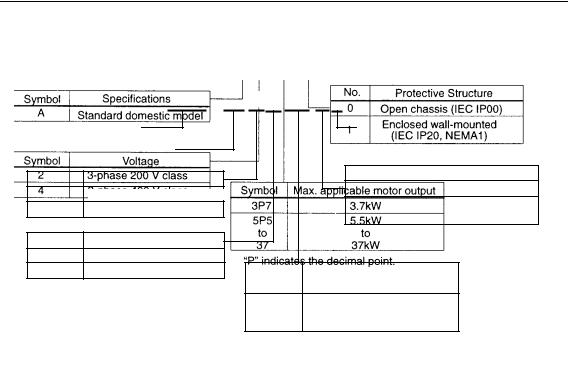
Model Designation
U
Standard domestic model
U American model
Protective Structure
•Open Chassis Type (IEC IP00)
Protected so that parts of the human body cannot reach electrically charged parts from the front when the Power regenerative unit is mounted in a control panel.
•Enclosed Wall-mounted Type (IEC IP20, NEMA 1)
The power regenerative unit is structured so that the power regenerative unit is shielded from the exterior, and can thus be mounted to the interior wall of a standard building (not necessarily enclosed in a control panel). The protective structure conforms to the standards of NEMA 1 in the USA.
12

2. SPECIFICATIONS
NOTE
1.Use 1 to 1 with an inverter. Do not connect more than one inverter to one power regenerative unit.
2.Use the power regenerative unit whose capacity is equal to or exceeding the inverter capacity to be combined.
3.Do not use this unit with single-phase power. Use three-phase power.
2.1Standard Specifications (200V Class)
|
|
|
Voltage Class |
|
|
|
|
|
|
200V |
|
|
|
|
|
|
|
|
|
Model CIMR-R5U |
23P7 |
|
25P5 |
27P5 |
|
2011 |
2015 |
2018 |
|
2022 |
2030 |
|
2037 |
|
|
|
Rated Capacity (kW) |
3.7 |
|
5.5 |
7.5 |
|
11 |
15 |
18.5 |
|
22 |
30 |
|
37 |
|
|
|
Rated DC Current (A) |
13 |
|
19 |
26 |
|
37 |
51 |
64 |
|
77 |
102 |
|
126 |
Rating |
Rated Current on |
10 |
|
15 |
20 |
|
30 |
40 |
50 |
|
60 |
80 |
|
100 |
||
Power Side (A) |
|
|
|
|
||||||||||||
|
|
|
|
|
|
|
|
|
|
|
|
|
||||
|
|
|
|
|
|
|
|
|
|
|
|
|
|
|
|
|
|
|
|
Regenerative Torque |
|
|
100% for 1 minute, 25% ED, 80% continuous |
|
|||||||||
Input Power |
|
|
Voltage Frequency |
|
|
200 to 220 VAC 50 Hz, 200 to 230 VAC 60 Hz |
|
|||||||||
|
|
Allowable Voltage Fluctuation |
|
+10 to -15% (Imbalance rate between phases: within 2% |
|
|||||||||||
Supply |
Allowable Frequency |
|
|
|
|
± 3Hz (No phase rotation) |
|
|
|
|
||||||
Fluctuation |
|
|
|
|
|
|
|
|
||||||||
|
|
|
|
|
|
|
|
|
|
|
|
|
||||
|
|
|
|
|
|
|
|
|
|
|
|
|
|
|||
|
|
|
Control Method |
|
|
|
|
120º current conduction |
|
|
|
|
||||
|
|
|
|
|
|
|
|
|
|
|
|
|||||
|
|
|
|
|
|
|
|
|
|
|
|
|
|
|
|
|
|
|
|
Input Power Factor |
|
|
|
0.9 or more (Rated current) |
|
|
|
||||||
|
|
|
|
|
|
|
|
|
|
|||||||
|
|
|
|
|
|
|
|
|
|
|
|
|
|
|
|
|
Control |
Characteristics |
Overload Capacity |
|
|
30 seconds at approx. 150% of rated current |
|
||||||||||
|
|
|
|
|||||||||||||
|
|
|
|
|
|
|
|
|
|
|
|
|
|
|||
Operation |
Input |
|
|
|
|
|
External terminals |
|
|
|
|
|||||
Status |
Output |
|
Fault |
|
|
|
|
|
I C contact output |
|
|
|
|
|||
|
Running, READY |
|
|
|
|
|
Photocoupler output |
|
|
|
|
|||||
|
Signal |
|
|
|
|
|
|
|
|
|
||||||
|
|
|
|
|
|
|
|
|
|
|
|
|
|
|||
|
|
|
Analog Output |
|
Analog output: 1 point can be selected (current monitor) |
|
||||||||||
|
|
|
Instantaneous Overcurrent |
|
|
Stops at approx. 200% of the current on power side |
|
|||||||||
|
|
|
Blown fuse |
|
|
|
|
|
Stops by blown fuse |
|
|
|
|
|||
Functions |
|
Overload |
|
|
Stops after 30 seconds at 150% of rated current |
|
||||||||||
|
Under voltage |
|
|
|
Stops at approx. 190 VDC or less. |
|
|
|
||||||||
|
(DC Voltage) |
|
|
|
|
|
|
|||||||||
|
|
|
|
|
|
|
|
|
|
|
|
|
|
|||
|
Under voltage |
|
|
|
Stops at approx. 150 VAC or less. |
|
|
|
||||||||
Protective |
|
(Power Side Voltage) |
|
|
|
|
|
|
|
|
|
|
|
|
|
|
|
Overload |
|
|
|
Stops at approx. 400 VDC or more. |
|
|
|
||||||||
|
Fin Overheat |
|
|
|
|
|
Protected by thermistor |
|
|
|
|
|||||
|
Power Supply Open Phase |
|
|
Stops at power supply open phase detection. |
|
|||||||||||
|
|
|
|
|
|
|||||||||||
|
|
|
Power Frequency Error |
Stops by fluctuation more than ± 3Hz of rated input frequency. |
||||||||||||
|
|
|
Power Charge Indication |
|
Indicated until main output voltage is approx. 50V or less. |
|
||||||||||
13

|
Voltage Class |
|
|
|
|
200V |
||||
|
Model CIMR-R5U |
23P7 |
25P5 |
27P5 |
2011 |
2015 |
2018 |
2022 |
2030 |
2037 |
Environmental Conditions |
Location |
|
Indoor |
(Protected from corrosive gases and dust) |
||||||
Ambient Temperature |
14°F (-10° C) to 104° F (40° C) (Enclosed wall-mounted type) |
|||||||||
|
14° F (-10° C) to 113° F (45° C) (Open chassis type) |
|||||||||
|
|
|||||||||
Humidity |
|
|
90% RH or less (non-condensing) |
|||||||
Vibration |
9.8 m/s2 (1G) at less than 20 Hz, up to 1.96 m/s2 (0.2G) at 20 to 50 Hz |
|||||||||
*Use a power regenerative unit with larger output capacity if the imbalance rate between phases exceeds 2%.
Imbalance rate between phases can be calculated using the following formula (Conforming to IEC1800-3).
Imbalance rate between phases [%] = Max voltage - Min. voltage X67
Three-phase average voltage
14
Loading...