


 Loading...
YASKAWA AC Drive V1000 Option
EtherNet/IP
Technical Manual
Type: SI-EN3D/V
To properly use the product, read this manual thoroughly and retain for easy reference, inspection, and maintenance. Ensure the end user receives this manual.
MANUAL NO. SIEP YAICOM 15A
Copyright © 2014 YASKAWA AMERICA, INC. All rights reserved.
No part of this publication may be reproduced, stored in a retrieval system, or transmitted, in any form or by any means, mechanical, electronic, photocopying, recording, or otherwise, without the prior written permission of Yaskawa. No patent liability is assumed with respect to the use of the information contained herein. Moreover, because Yaskawa is constantly striving to improve its high-quality products, the information contained in this manual is subject to change without notice. Every precaution has been taken in the preparation of this manual. Yaskawa assumes no responsibility for errors or omissions. Neither is any liability assumed for damages resulting from the use of the information contained in this publication.

Table of Contents
1 |
PREFACE AND SAFETY......................................................................................... |
4 |
2 |
PRODUCT OVERVIEW............................................................................................ |
7 |
3 |
RECEIVING.............................................................................................................. |
8 |
4 |
OPTION COMPONENTS.......................................................................................... |
9 |
5 |
INSTALLATION PROCEDURE.............................................................................. |
12 |
6 |
RELATED DRIVE PARAMETERS......................................................................... |
20 |
7 |
CONFIGURING MESSAGING................................................................................ |
23 |
8 |
OUTPUT ASSEMBLIES (DRIVE CONSUMES)..................................................... |
24 |
9 |
INPUT ASSEMBLIES (DRIVE PRODUCES)......................................................... |
31 |
10 |
GENERAL CLASS OBJECTS............................................................................... |
42 |
11 |
VENDOR-SPECIFIC (YASKAWA) CLASS OBJECTS.......................................... |
51 |
12 |
WEB INTERFACE.................................................................................................. |
53 |
13 |
TROUBLESHOOTING............................................................................................ |
60 |
14 |
SPECIFICATIONS.................................................................................................. |
63 |
YASKAWA SIEP YAICOM 15A V1000 Option Dual-Port EtherNet/IP SI-EN3D/V Technical Manual |
3 |
1Preface and Safety
1Preface and Safety
Yaskawa manufactures products used as components in a wide variety of industrial systems and equipment. The selection and application of Yaskawa products remain the responsibility of the equipment manufacturer or end user. Yaskawa accepts no responsibility for the way its products are incorporated into the final system design. Under no circumstances should any Yaskawa product be incorporated into any product or design as the exclusive or sole safety control. Without exception, all controls should be designed to detect faults dynamically and fail safely under all circumstances. All systems or equipment designed to incorporate a product manufactured by Yaskawa must be supplied to the end user with appropriate warnings and instructions as to the safe use and operation of that part. Any warnings provided by Yaskawa must be promptly provided to the end user. Yaskawa offers an express warranty only as to the quality of its products in conforming to standards and specifications published in the Yaskawa manual. NO OTHER WARRANTY, EXPRESS OR IMPLIED, IS OFFERED. Yaskawa assumes no liability for any personal injury, property damage, losses, or claims arising from misapplication of its products.
u Applicable Documentation
The following manuals are available for the SI-EN3D/V option:
Yaskawa AC Drive V1000 Option SI-EN3D/V Dual-Port EtherNet/IP Installation Manual (TOEPYAICOM15)
The Installation Manual contains information required to install the option and set up related drive parameters.
Yaskawa AC Drive V1000 Option SI-EN3D/V Dual-Port EtherNet/IP Technical Manual (SIEPYAICOM15)
The Technical Manual contains detailed information about the option. In the U.S., access http://www.yaskawa.com to obtain the Technical Manual. Customers in other areas should contact a Yaskawa representative.
V1000 Series AC Drive Quick Start Guide
This guide contains basic information required to install and wire the drive. It also gives an overview of fault diagnostics, maintenance, and parameter settings. The purpose of this guide is to prepare the drive for a trial run with an application and for basic operation. This manual is available for download on our documentation website, www.yaskawa.com.
V1000 Series AC Drive Technical Manual
This manual provides detailed information on parameter settings, drive functions, and MEMOBUS/Modbus specifications. Use this manual to expand drive functionality and to take advantage of higher performance features. This manual is available for download on our documentation website, www.yaskawa.com.
u Terms
Note: Indicates supplemental information that is not related to safety messages. Drive: Yaskawa V1000 Series AC Drive
Option: Yaskawa AC Drive V1000 SI-EN3D/V Dual-Port EtherNet/IP Option
u Registered Trademarks
•EtherNet/IP is a trademark of the ODVA.
•All trademarks are the property of their respective owners.
u Supplemental Safety Information
Read and understand this manual before installing, operating, or servicing this option. The option must be installed according to this manual and local codes.
The following conventions are used to indicate safety messages in this manual. Failure to heed these messages could result in serious or possibly even fatal injury or damage to the products or to related equipment and systems.
 DANGER
Indicates a hazardous situation, which, if not avoided, will result in death or serious injury.
4 |
YASKAWA SIEP YAICOM 15A V1000 Option Dual-Port EtherNet/IP SI-EN3D/V Technical Manual |

1 Preface and Safety
 WARNING
Indicates a hazardous situation, which, if not avoided, could result in death or serious injury.
WARNING! may also be indicated by a bold key word embedded in the text followed by an italicized safety message.
 CAUTION
Indicates a hazardous situation, which, if not avoided, could result in minor or moderate injury.
CAUTION! may also be indicated by a bold key word embedded in the text followed by an italicized safety message.
NOTICE
Indicates a property damage message.
NOTICE: may also be indicated by a bold key word embedded in the text followed by an italicized safety message.
n General Safety
General Precautions
•The diagrams in this manual may be indicated without covers or safety shields to show details. Replace the covers or shields before operating the drive and run the drive according to the instructions described in this manual.
•Any illustrations, photographs, or examples used in this manual are provided as examples only and may not apply to all products to which this manual is applicable.
•The products and specifications described in this manual or the content and presentation of the manual may be changed without notice to improve the product and/or the manual.
•When ordering a new copy of the manual due to damage or loss, contact your Yaskawa representative or the nearest Yaskawa sales office and provide the manual number shown on the front cover.
•If nameplate becomes worn or damaged, order a replacement from your Yaskawa representative or the nearest Yaskawa sales office.
 DANGER
Heed the safety messages in this manual.
Failure to comply will result in death or serious injury.
The operating company is responsible for any injuries or equipment damage resulting from failure to heed the warnings in this manual.
Electrical Shock Hazard
Do not connect or disconnect wiring while the power is on.
Failure to comply will result in death or serious injury.
Failure to comply will result in death or serious injury. Before servicing, disconnect all power to the equipment. The internal capacitor remains charged even after the power supply is turned off. The charge indicator LED will extinguish when the DC bus voltage is below 50 Vdc. To prevent electric shock, wait for at least the time specified on the warning label once all indicators are OFF, and then measure the DC bus voltage level to confirm it has reached a safe level.
NOTICE
Observe proper electrostatic discharge procedures (ESD) when handling the drive and circuit boards.
Failure to comply may result in ESD damage to the drive circuitry.
Do not perform a withstand voltage test on any part of the drive.
Failure to comply could result in damage to the sensitive devices within the drive.
Do not operate damaged equipment.
Failure to comply could result in further damage to the equipment.
Do not connect or operate any equipment with visible damage or missing parts.
YASKAWA SIEP YAICOM 15A V1000 Option Dual-Port EtherNet/IP SI-EN3D/V Technical Manual |
5 |
1 Preface and Safety
NOTICE
Do not expose the drive to halogen group disinfectants.
Failure to comply may cause damage to the electrical components in the drive.
Do not pack the drive in wooden materials that have been fumigated or sterilized.
Do not sterilize the entire package after the product is packed.
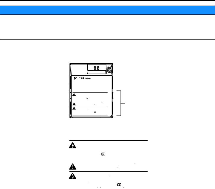
n Option Unit Warning Labels
Warning information is displayed on the option unit as shown in the figure below. Follow all warnings and safety instructions when using the product.
V1000
 WARNING Risk of electric shock.
 Read manual before installing.
 Wait 5 minutes for capacitor discharge after disconnecting power supply.
 To conform to requirements, make sure to ground the supply neutral for 400V class.
AVERTISSEMENT Risque de decharge electrique.
 Lire le manuel avant l'installation.
 Attendre 5 minutes apres la coupure de l'alimentation, pour permettre la decharge des condensateurs.
 Pour repondre aux exigences , s assurer que le neutre soit relie a la terre, pour la serie 400V.
Warning information
n Warning Contents
 WARNING Risk of electric shock.
 Read manual before installing.
 Wait 5 minutes for capacitor discharge after disconnecting power supply.
 To conform to requirements, make sure to ground the supply neutral for 400V class.
AVERTISSEMENT Risque de decharge electrique.
 Lire le manuel avant l'installation.
 Attendre 5 minutes apres la coupure de l'alimentation, pour permettre la decharge des condensateurs.
 Pour repondre aux exigences , s assurer que le neutre soit relie a la terre, pour la serie 400V.
6 |
YASKAWA SIEP YAICOM 15A V1000 Option Dual-Port EtherNet/IP SI-EN3D/V Technical Manual |

2 Product Overview
2Product Overview
u About this Product
The option provides a communications connection between the drive and an ODVA EtherNet/IP network. The option connects the drive to an EtherNet/IP network and facilitates the exchange of data.
This manual explains the handling, installation and specifications of this product.
EtherNet/IP is a communications link to connect industrial devices (such as smart motor controllers, operator interfaces, and variable frequency drives) as well as control devices (such as programmable controllers and computers) to a network. EtherNet/ IP is a simple, networking solution that reduces the cost and time to wire and install factory automation devices, while providing interchangeability of like components from multiple vendors.
EtherNet/IP is an open device network standard.
By installing the option to a drive, it is possible to do the following from an EtherNet/IP master device:
•Operate the drive
•Monitor drive status
•Change drive parameter settings.
u Applicable Models
The option can be used with the drive models in Table 1.
Table 1 Applicable Models
Drive Series |
Drive Model Number |
Software Version <1> |
V1000 |
CIMR-VooAoooo |
1012 and later |
<1> See “PRG” on the drive nameplate for the software version number.
YASKAWA SIEP YAICOM 15A V1000 Option Dual-Port EtherNet/IP SI-EN3D/V Technical Manual |
7 |
3Receiving
3Receiving
Please perform the following tasks upon receipt of the option:
•Inspect the option for damage. Contact the shipper immediately if the option appears damaged upon receipt.
•Verify receipt of the correct model by checking the model number printed on the name plate of the option package.
•Contact your supplier if you have received the wrong model or the option does not function properly.
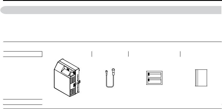
u Option Package Contents
Description |
Option Unit |
Ground Wire |
Warning Labels |
Installation Manual |
|
|
|
|
|
MANUAL
–
Quantity |
1 |
4 |
1 |
1 |
u Tools Required for Installation
A Phillips screwdriver (M3, M3.5 to M6 metric or #1, #2 U.S. standard) is required to install the option. Screw sizes vary by drive capacity. Select a screwdriver appropriate for the drive capacity.
Note: Tools required to prepare the option cables for wiring are not listed in this manual.
8 |
YASKAWA SIEP YAICOM 15A V1000 Option Dual-Port EtherNet/IP SI-EN3D/V Technical Manual |
4 Option Components
4Option Components
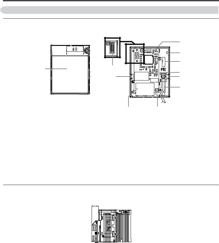
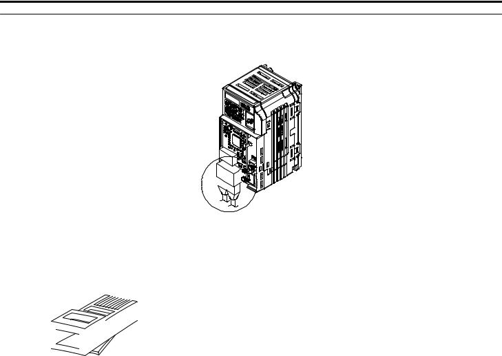
u SI-EN3D/V Dual-Port EtherNet/IP Option Unit
Option with cover attached
A 
B

C
Option with cover removed |
|
|||||
Underside |
|
|
|
|
|
|
|
|
|
|
|
|
D |
|
|
|
|
EN3D/V 1XXX |
00000000000000 |
E |
|
|
|
|
F |
||
|
|
|
|
|
|
|
R |
|
|
|
SI- |
|
|
|
|
|
|
|
|
|
|
|
|
|
|
|
G |
H |
|
|
|
|
|
H |
|
|
|
|
|
|
I |
|
|
O |
L |
|
|
|
Q |
P |
N M |
K |
J |
|
|
A – LED (NS) <2>
B – LED (MS) <2> C – Option cover
D – EtherNet/IP PCB
E – Attachment screw hole for option cover
F – Nameplate
G – Functional earth cable connection (FE)
H – Mounting tab
I – Ground wire <1>
J – Pass-through hole for ground wire K – Port 2 LED (10/100) <2>
L – Port 2
M – Port 2 LED (LINK/ACT) <2> N – Port 1 LED (10/100) <2>
O – Port 1
P – Port 1 LED (LINK/ACT) <2> Q – EtherNet/IP cable connector R – Option connector
|
Figure 1 Option Unit Components |
<1> |
A selection of ground wires are packaged loose in the option shipping package. Connect the appropriate ground wire based on |
|
drive model during installation. |
<2> |
Refer to Option LED Display on page 11 for details on the LEDs. |
u Dimensions
The installed option adds 27 mm (1.06 in.) to the total depth of the drive.
27 mm (1.06 in.)
Figure 2 Dimensions
YASKAWA SIEP YAICOM 15A V1000 Option Dual-Port EtherNet/IP SI-EN3D/V Technical Manual |
9 |
4 Option Components
u Communication Connector CN1
Communication Connector CN1 is a modular RJ45 female connector and the connection point for a customer-supplied male Ethernet network communication cable.
|
|
|
|
|
|
|
|
|
|
|
|
|
|
|
|
|
|
|
|
|
|
|
|
|
|
|
Figure 3 Communication Connector CN1 (RJ45) |
||
|
|
|
|
|
|
|
|
|
|
|
|
|
Table 2 Male, 8-Way Ethernet Modular Connector (Customer-Supplied) |
||||||||||||||||
Male Ethernet 8-Way Modular Connector |
Pin |
Description |
|||||||||||||||||||||||||||
|
|
|
|
|
|
|
|
|
|
|
|
|
|
|
|
|
|
|
|
|
|
|
|
|
|
|
|
|
|
|
|
|
|
|
|
|
|
|
|
|
|
|
|
|
|
|
|
|
|
|
|
|
|
|
|
|
|
1 (Pair 2) |
Transmit data (TXD) + |
|
|
|
|
|
|
|
|
|
|
|
|
|
|
|
|
|
|
|
|
|
|
|
|
|
|
|
|
2 (Pair 2) |
Transmit data (TXD) - |
|
|
|
|
|
|
|
|
|
|
|
|
|
|
|
|
|
|
|
|
|
|
|
|
|
|
|
|
3 (Pair 3) |
Receive data (RXD) + |
|
|
|
|
|
|
|
|
|
|
|
|
|
|
|
|
|
|
|
|
|
|
|
|
|
|
|
|
||
|
|
|
|
|
|
|
|
|
|
|
|
|
|
|
|
|
|
|
|
|
|
|
|
|
|
|
|
|
|
|
1 |
2 3 |
4 5 |
|
|
|
|
|
|
|
|
|
|
|
|
|
|
|
|
|
|
|
|
|
|
|
|
4 (Pair 1) |
Not used <1> |
|
|
|
|
|
|
|
|
|
|
|
|
|
|
|
|
|
|
|
|
|
|
|
|
|
|||||
|
|
|
|
|
|
|
|
|
|
|
|
|
|
|
|
|
|
|
|
|
|
|
|
|
|||||
|
|
|
|
|
|
|
|
|
|
|
|
|
|
|
|
|
|
|
|
|
|
|
|
|
|||||
|
6 |
7 |
8 |
|
|
|
|
|
|
|
|
|
|
|
|
|
|
|
|
|
|
|
|
|
5 (Pair 1) |
Not used <1> |
|||
|
|
|
|
|
|
|
|
|
|
|
|
|
|
|
|
|
|
|
|
|
|
|
|
||||||
|
|
|
|
|
|
|
|
|
|
|
|
|
|
|
|
|
|
|
|
|
|
|
|
|
|
|
|
||
|
|
|
|
|
|
|
|
|
|
|
|
|
|
|
|
|
|
|
|
|
|
|
|
|
|
|
|
|
|
|
|
|
|
|
|
|
|
|
|
|
|
|
|
|
|
|
|
|
|
|
|
|
|
|
|
|
|
6 (Pair 3) |
Receive data (RXD) - |
|
|
|
|
|
|
|
|
|
|
|
|
|
|
|
|
|
|
|
|
|
|
|
|
|
|
|
|
||
|
|
|
|
|
|
|
|
|
|
|
|
||||||||||||||||||
|
|
|
|
|
|
|
|
|
Latch release |
7 (Pair 4) |
Not used <1> |
||||||||||||||||||
|
|
|
|
|
|
|
|
||||||||||||||||||||||
|
|
|
|
|
|
|
|
|
|
|
|
|
|
|
|
|
|
|
|
|
|
|
|
|
|
|
|
8 (Pair 4) |
Not used <1> |
<1> Not used for 10 Mbps and 100 Mbps networks.
10 |
YASKAWA SIEP YAICOM 15A V1000 Option Dual-Port EtherNet/IP SI-EN3D/V Technical Manual |
4 Option Components
u Option LED Display
The option has four LEDs.
Bi-color Status LEDs:
•Module status (MS) red/green
•Network status (NS) red/green
Ethernet LEDs:
•Network speed - 10/100 (MS) green
•Link status and network activity - LINK/ACT (NS) red/green
The operational states of the option LEDs after completion of the power-up diagnostic LED sequence are described in Table 3. Wait at least 2 seconds for the power-up diagnostic process to complete before verifying LED states.
Table 3 Option LED States
Name |
|
Display |
Operating Status |
Remarks |
||
Color |
|
Status |
||||
|
|
|
|
|
||
|
|
– |
|
OFF |
Power supply OFF |
Power is not being supplied to the drive. |
|
|
Green |
|
ON |
Normal operation |
The option is operating normally and initialization is |
|
|
|
complete. |
|||
|
|
|
|
|
|
|
|
|
Green |
|
Flashing |
Standby/Initializing |
The option is in process of configuring or waiting for |
MS |
|
|
configuration information. |
|||
|
|
|
|
|
||
|
|
Red |
|
Flashing |
Non-fatal error occurred |
The option has detected a recoverable minor fault such |
|
|
|
as incomplete configuration. |
|||
|
|
|
|
|
|
|
|
|
Red |
|
ON |
Fatal error occurred |
The option has detected an unrecoverable major fault. |
|
|
Green/Red |
|
Flashing |
Option self-test |
The option is in self-test mode. |
|
|
– |
|
OFF |
Power supply OFF |
– |
|
|
Green |
|
ON |
Online communications |
The option is online and has established connections. |
|
|
|
established |
|||
|
|
|
|
|
|
|
NS |
|
Green |
|
Flashing |
Not connected |
The option is online without an established connection. |
|
|
Red |
|
Flashing |
Minor fault |
A minor recoverable fault has occurred. |
|
|
Red |
|
ON |
Major fault |
The option detected a duplicate IP address. |
|
|
Green/Red |
|
Flashing |
Option self-test |
The option is in self-test mode. |
10/100 |
<1> |
Green |
|
OFF |
10 Mbps is established |
|
Green |
|
ON |
100 Mbps is established |
|
||
|
|
|
|
|||
|
|
Green |
|
OFF |
LINK is not established |
– |
LINK/ACT <1> |
Green |
|
ON |
LINK is established |
||
|
|
|||||
Green |
|
Flashing |
LINK is established and there is |
|
||
|
|
|
network activity. |
|
||
|
|
|
|
|
|
|
<1> Remove the cover to check the status of the LED. Be careful not to touch the main circuit terminals or the control board in the drive. |
||||||
n Power-Up Diagnostics
An LED test is performed each time the drive is powered up. The initial boot sequence may take several seconds. After the LEDs have completed the diagnostic LED sequence, the option is successfully initialized. The LEDs then assume operational conditions as shown in Table 3.
Table 4 Power-Up Diagnostic LED Sequence
Sequence |
Module Status (MS) |
Network Status (NS) |
Time (ms) |
1 |
Green |
OFF |
250 |
2 |
Red |
OFF |
250 |
|
|
|
|
3 |
Green |
OFF |
– |
4 |
Green |
Green |
250 |
5 |
Green |
Red |
250 |
6 |
Green |
OFF |
– |
YASKAWA SIEP YAICOM 15A V1000 Option Dual-Port EtherNet/IP SI-EN3D/V Technical Manual |
11 |

5Installation Procedure
5Installation Procedure
u Section Safety
 DANGER
Electrical Shock Hazard
Do not connect or disconnect wiring while the power is on.
Failure to comply will result in death or serious injury.
Disconnect all power to the drive and wait at least the amount of time specified on the drive front cover safety label. After all indicators are off, measure the DC bus voltage to confirm safe level, and check for unsafe voltages before servicing. The internal capacitor remains charged after the power supply is turned off.
 WARNING
Electrical Shock Hazard
Do not remove the option unit cover while the power is on.
Failure to comply could result in death or serious injury.
The diagrams in this section may include options and drives without covers or safety shields to show details. Be sure to reinstall covers or shields before operating any devices. The option should be used according to the instructions described in this manual.
Do not allow unqualified personnel to use equipment.
Failure to comply could result in death or serious injury.
Maintenance, inspection, and replacement of parts must be performed only by authorized personnel familiar with installation, adjustment, and maintenance of this product.
Do not use damaged wires, stress the wiring, or damage the wire insulation.
Failure to comply could result in death or serious injury.
Do not use damaged wires, place excessive stress on wiring, or damage the wire insulation.
Failure to comply could result in death or serious injury.
Fire Hazard
Tighten all terminal screws to the specified tightening torque.
Loose electrical connections could result in death or serious injury by fire due to overheating of electrical connections.
NOTICE
Observe proper electrostatic discharge procedures (ESD) when handling the drive and circuit boards.
Failure to comply may result in ESD damage to the drive circuitry.
Never shut the power off while the drive is outputting voltage.
Failure to comply may cause the application to operate incorrectly or damage the drive.
Do not operate damaged equipment.
Failure to comply may cause further damage to the equipment.
Do not connect or operate any equipment with visible damage or missing parts.
Do not use unshielded cable for control wiring.
Failure to comply may cause electrical interference resulting in poor system performance. Use shielded twisted-pair wires and ground the shield to the ground terminal of the drive.
12 |
YASKAWA SIEP YAICOM 15A V1000 Option Dual-Port EtherNet/IP SI-EN3D/V Technical Manual |
5 Installation Procedure
NOTICE
Properly connect all pins and connectors.
Failure to comply may prevent proper operation and possibly damage equipment.
Check wiring to ensure that all connections are correct after installing the option and connecting any other devices.
Failure to comply could result in damage to the option.
u Prior to Installing the Option
Prior to installing the option, wire the drive, make necessary connections to the drive terminals, and verify that the drive functions normally without the option installed. Refer to the drive Quick Start Guide for information on wiring and connecting the drive.
u Installing the Option
DANGER! DANGER! Electrical Shock Hazard. Do not connect or disconnect wiring while the power is on. Failure to comply could result in death or serious injury. Before installing the option, disconnect all power to the drive and wait at least the amount of time specified on the drive front cover safety label. After all indicators are off, measure the DC bus voltage to confirm safe level, and check for unsafe voltages before servicing. The internal capacitor remains charged after the power supply is turned off.
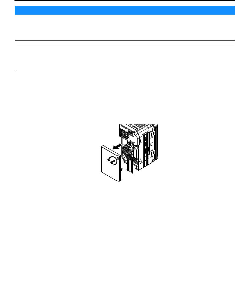
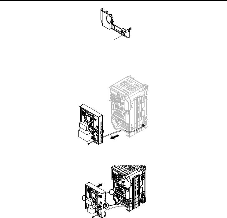
1.Shut off power to the drive, wait at least five minutes after confirming the DC bus voltage is safe, then loosen the screw that fastens the front cover in place and remove the front cover. This drive front cover will be replaced by the option cover. Cover removal varies depending on drive size.
NOTICE: Damage to Equipment. Observe proper electrostatic discharge procedures (ESD) when handling the option, drive, and circuit boards. Failure to comply may result in ESD damage to circuitry.
Figure 4 Remove the Front Cover
2.The remaining installation steps differ based on drive model. Find the drive model number on the drive nameplate and refer to the step indicated in Table 5 based on your model number
Table 5 Installation Steps Based on Drive Model
Enclosure Type |
Drive Model |
Proceed to Step |
Page |
IP20/Open-Chassis |
CIMR-VooAooooB |
3 |
13 |
IP20/NEMA Type 1 <1> |
CIMR-VooAooooF |
6 |
15 |
Installing<1> the option on an IP20/NEMA Type 1 enclosure drive voids NEMA Type 1 protection while maintaining IP20 conformity.
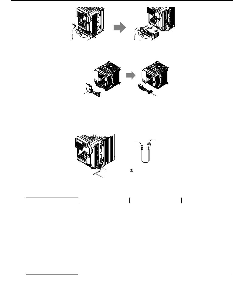
3.For IP20/Open-Chassis models CIMR-VooAooooB, remove the bottom cover of the drive by applying pressure to the tabs on each side of the bottom cover. Pull the bottom cover away from the drive while pushing in on the tabs to release the cover from the drive. Refer to Figure 5 for details.
Refer to Figure 6 for drive models BA0006B to BA0018B, 2A0008B to 2A0069B, and 4A0001B to 4A0038B, which require removing the terminal cover prior to removing the bottom cover.
YASKAWA SIEP YAICOM 15A V1000 Option Dual-Port EtherNet/IP SI-EN3D/V Technical Manual |
13 |
5 Installation Procedure
Figure 5 Remove the Bottom Cover on an IP20/Open-Chassis Drive (Models BA0001B to BA0003B and 2A0001B to 2A0006B)
Terminal Cover |
Bottom Cover |
Figure 6 Remove the Terminal Cover and Bottom Cover on an IP20/Open-Chassis Drive (Models BA0006B to BA0018B; 2A0008B to 2A0069B; 4A0001B to 4A0038B)
4. On IP20/Open-Chassis models, connect the drive side of the ground wire to the drive ground terminal.
Note: The different ground wires packaged with the option connect the option to different drive models. Select the proper ground wire depending on drive size. Refer to Table 6 for ground wire selection by drive model.
Option unit |
|
Drive-side |
|
connector |
|
||
|
connector |
||
Screw size: M3 |
|||
Screw size: |
|||
|
|
||
|
|
M3.5 to M6 |
|
|
Ground wire |
||
Ground terminal |
|
|
|
Figure 7 Connect the Ground Wire on an IP20/Open-Chassis Drive
Table 6 Ground Wire Selection
Ground Wire Length |
|
Drive Model |
|
|
Single-Phase |
Three-Phase |
Three-Phase |
||
(mm/in) |
||||
|
200 V Class |
200 V Class |
400 V Class |
|
|
BA0001 |
2A0001 |
|
|
|
2A0002 |
|
||
150/5.9 |
BA0002 |
– |
||
2A0004 |
||||
|
BA0003 |
|
||
|
2A0006 |
|
||
|
|
|
||
|
|
|
4A0001 |
|
|
BA0006 |
|
4A0002 |
|
|
2A0010 |
4A0004 |
||
|
BA0010 |
|||
200/7.9 |
2A0012 |
4A0005 |
||
BA0012 |
||||
|
2A0020 |
4A0007 |
||
|
BA0018 |
|||
|
|
4A0009 |
||
|
|
|
4A0011 |
|
250/9.8 |
– |
2A0030 |
4A0018 |
|
2A0040 |
4A0023 |
|||
|
|
|||
400/15.7 |
– |
2A0056 |
4A0031 |
|
2A0069 |
4A0038 |
|||
|
|
5. For IP20/Open-Chassis models, go to Step 9. on page 36.
14 |
YASKAWA SIEP YAICOM 15A V1000 Option Dual-Port EtherNet/IP SI-EN3D/V Technical Manual |
5 Installation Procedure
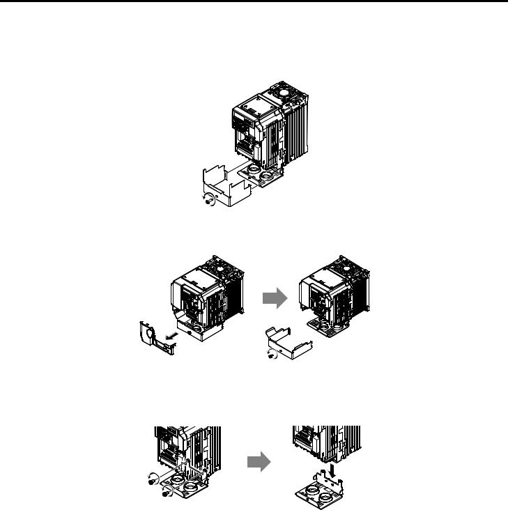
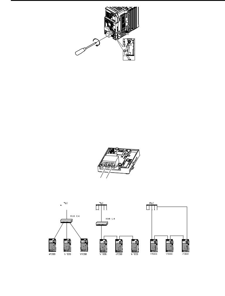
6.For IP20/NEMA Type 1 enclosure models CIMR-VooAooooF, loosen the screw on the front of the NEMA Type 1 terminal cover and remove it from the drive. Refer to Figure 8 for details.
Refer to Figure 9 for drive models BA0006F to BA0018F, 2A0010F to 2A0069F, and 4A0001F to 4A0038F, which require removing the plastic terminal cover prior to removing the NEMA Type 1 terminal cover.
Note: Installing the option on an IP20/NEMA Type 1 enclosure drive voids NEMA Type 1 protection while maintaining IP20 conformity.
Figure 8 Remove the NEMA Type 1 Terminal Cover (Models BA0001F to BA0003F and 2A0001F to 2A0006F)
Figure 9 Remove the Terminal Cover on an IP20/NEMA Type 1 Drive (Models BA0006F to BA0018F; 2A0008F to 2A0069F; 4A0001F to 4A0038F)
7.For models BA0001F to BA0003F and 2A0001F to 2A0006F, loosen the screws attaching the NEMA Type 1 conduit bracket to the drive to remove the NEMA Type 1 conduit bracket.
Figure 10 Remove the NEMA Type 1 Conduit Bracket (Models BA0001F to BA0003F and 2A0001F to 2A0006F)
8.On models (BA0001F to BA0003F and 2A0001F to 2A0006F), the screw for the drive ground terminal also acts as one of the screws that attaches the NEMA Type 1 conduit bracket to the drive. Reattach the NEMA Type 1 conduit bracket according to Figure 27 and connect the drive-side of the ground wire to the drive ground terminal.
Note: The different ground wires packaged with the option connect the option to different drive models. Select the proper ground wire depending on drive size. Refer to Table 6 on page 14 for ground wire selection by drive model.
YASKAWA SIEP YAICOM 15A V1000 Option Dual-Port EtherNet/IP SI-EN3D/V Technical Manual |
15 |

5 Installation Procedure
Drive ground terminal/ 
 NEMA Type 1 conduit


 bracket screw


Option unit |
|
Drive-side |
|
connector |
|
||
|
connector |
||
Screw size: M3 |
|||
Screw size: |
|||
|
|
||
Ground terminal |
|
M3.5 to M6 |
|
|
|
||
|
Ground wire |
||
 Ground wire
Figure 11 Reattach the NEMA Type 1 Conduit Bracket and Connect the Ground Wire (Models BA0001F to BA0003F and 2A0001F to 2A0006F)
9. Reattach the bottom cover. Keep the ground wire inside of the bottom cover when reattaching.
IP20/Open-Chassis |
IP20/NEMA Type 1 Enclosure |
Figure 12 Reattach the Bottom Cover
10.On models BA0006 to BA0018, 2A0008 to 2A0069, and 4A0001 to 4A0038, reattach the terminal cover.
Refer to Figure 13 and Figure 14 for drive models BA0006 to BA0018, 2A0008 to 2A0020, and 4A0001 to 4A0011, which require routing the ground wire through the provided notch when reinstalling the terminal cover.
Figure 13 Reattach the Terminal Cover
(Models BA0006 to BA0018; 2A0008 to 2A0069; 4A0001 to 4A0038)
16 |
YASKAWA SIEP YAICOM 15A V1000 Option Dual-Port EtherNet/IP SI-EN3D/V Technical Manual |
5 Installation Procedure
Ground wire routing notch
Figure 14 Terminal Cover Ground Wire Notch
(Models BA0006 to BA0018; 2A0008 to 2A0020; 4A0001 to 4A0011)
11.Remove the option cover and pass the ground wire through the inside of the drive bottom cover and into the throughhole for the ground wire at the front of the option.
Figure 15 Ground Wire Routing
12.Attach the option to the drive. Properly seat the tabs on the left and right sides of the option to the drive case.
Line up tabs
Line up tabs
Figure 16 Connect the Option
13.Connect the ground wire at the option ground terminal. Tighten the screw to 0.5 to 0.6 N•m or (4.4 to 5.3 in lbs) using an M3 Phillips screwdriver.
YASKAWA SIEP YAICOM 15A V1000 Option Dual-Port EtherNet/IP SI-EN3D/V Technical Manual |
17 |
5 Installation Procedure
Option ground terminal |
Figure 17 Connect the Ground Wire to the Option
14.Connect the Ethernet communication cable to the option modular connector (CN1) port 1.
To connect the option to a network, firmly connect RJ45 8-pin shielded twisted pair Cat5e cable(s) into the modular connector ports (see Figure 18).
IGMP Snooping
Switches implementing IGMP Snooping are strongly recommended. When IGMP Snooping is used, devices will only receive the multicast packets in which they are interested.
Communication Cable Specifications
Only use cable recommended for EtherNet/Industrial Protocol (EtherNet/IP™). Using a cable not specifically recommended may cause the option or drive to malfunction. Refer to the ODVA website for more information on network cabling (http://www.odva.org).
The dual RJ45 network ports on the option board act as a switch to allow for flexibility in cabling topology. For example, a traditional star network topology may be employed by using a single port on the option board. Alternatively, a daisychained approach may be employed by using both RJ45 ports. The daisy-chained approach reduces the requirements of central switch ports. A ring topology is also possible.
Figure 18 Communication Cable Ports
Star Topology |
|
Daisy-Chained Topology |
|
Ring Topology |
||||||
|
|
|
|
|
|
|
|
|
|
|
|
|
|
|
|
|
|
|
|
|
|
|
|
|
|
|
|
|
|
|
|
|
|
|
|
|
|
|
|
|
|
|
|
|
|
|
|
|
|
|
|
|
|
|
|
|
|
|
|
|
|
|
|
|
|
V1000 |
V1000 |
V1000 |
V1000 |
V1000 |
V1000 |
V1000 |
V1000 |
V1000 |
Figure 19 Topology Options
18 |
YASKAWA SIEP YAICOM 15A V1000 Option Dual-Port EtherNet/IP SI-EN3D/V Technical Manual |
5 Installation Procedure
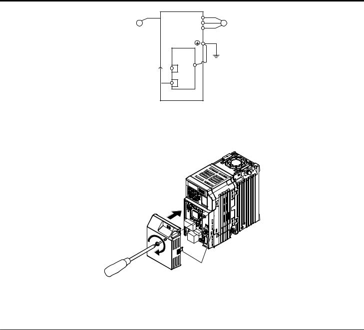
 R/L1 Power
 S/L2
S/L2  T/L3
T/L3
EtherNet/IP Cable
EtherNet/IP Cable 
U/T1 |
|
|
V/T2 |
M |
Motor |
W/T3 |
|
|
V1000 |
<1> |
|
|
|
|
SI-EN3D/V |
|
|
EtherNet/IP |
|
|
Option |
FE |
|
|
|
Figure 20 Option Connection Diagram
15.Use the second communication cable port to daisy chain a series of drives where applicable.
16.Attach the option cover by aligning the tabs with the mounting holes, seat the front cover into place, and tighten the screw on the front.
Line up tabs
Figure 21 Attach the Option Cover
Note: Take proper precautions when wiring the option so that the front covers will easily fit back onto the drive. Make sure no cables are pinched between the front covers and the drive when replacing the covers.
17.Set drive parameters in Table 7 for proper option performance.
u EDS Files
For easy network implementation of drives equipped with the option, an EDS file can be obtained from: U.S.: http://www.yaskawa.com
Europe: http://www.yaskawa.eu.com Japan: http://www.e-mechatronics.com
Other areas: Contact a Yaskawa representative.
Note: Download the option EDS file. The option will not function as a slave in the network without the appropriate EDS file.
YASKAWA SIEP YAICOM 15A V1000 Option Dual-Port EtherNet/IP SI-EN3D/V Technical Manual |
19 |

6Related Drive Parameters
6Related Drive Parameters
The following parameters are used to set up the drive for operation with the option. Parameter setting instructions can be found in the drive manual.
Confirm proper setting of the parameters in Table 7 before starting network communications. After changing parameter settings, cycle power to the drive for the new settings to take effect.
Table 7 Related Parameters
No. |
Name |
Description |
Values |
|
(Addr. |
||||
Hex) |
|
|
|
|
b1-01 |
|
0: Digital operator |
|
|
Frequency Reference Selection |
1: Analog input terminals |
Default: 1 |
||
(0180) |
2: MEMOBUS/Modbus communications |
|||
<1> |
1 |
3: Option PCB |
Range: 0 to 4 |
|
|
|
4: Pulse input (terminal RP) |
|
|
b1-02 |
|
0: Digital operator |
|
|
Run Command |
1: Digital input terminals |
Default: 1 |
||
(0181) |
||||
Selection 1 |
2: MEMOBUS/Modbus communications |
Range: 0 to 3 |
||
<1> |
||||
|
|
3: Option PCB |
|
|
|
|
0: Ramp to stop. Decelerate to stop using the deceleration time in C1-02. |
|
|
F6-01 |
Communications Error |
1: Coast to stop |
Default: 1 |
|
(03A2) |
Operation Selection |
2: Fast Stop. Decelerate to stop using the deceleration time in C1-09. |
Range: 0 to 3 |
|
|
|
3: Alarm only <2> |
|
|
F6-02 |
External Fault from Comm. |
1: Detection during run only |
Default: 0 |
|
(03A3) |
Option Detection Selection |
Range: 0, 1 |
||
|
||||
|
|
0: Ramp to stop. Decelerate to stop using the deceleration time in C1-02. |
|
|
F6-03 |
External Fault from Comm. |
1: Coast to stop |
Default: 1 |
|
(03A4) |
Option Operation Selection |
2: Fast Stop. Decelerate to stop using the deceleration time in C1-09. |
Range: 0 to 3 |
|
|
|
3: Alarm only <2> |
|
|
F6-07 |
Multi-Step Speed Enable/ |
0: Multi-step reference disabled (same as F7) |
Default: 1 |
|
Disable Selection when |
||||
(03A8) |
1: Multi-step reference enabled (same as V7) |
Range: 0, 1 |
||
NefRef/ComRef is Selected |
||||
|
|
|
||
F6-08 |
|
0: Communication-related parameters (F6-oo/F7-oo) are not reset when |
|
|
Reset Communication |
the drive is initialized using A1-03. |
Default: 0 |
||
(036A) |
||||
Parameters |
1: Reset all communication-related parameters |
Range: 0, 1 |
||
<3> |
||||
|
|
(F6-oo/F7-oo) when the drive is initialized using A1-03. |
|
|
F6-14 |
bUS Error Auto Reset |
0: Disabled |
Default: 0 |
|
(03BB) |
1: Enabled |
Range: 0, 1 |
||
|
||||
F7-01 |
|
|
Default: 192 |
|
(03E5) |
IP Address 1 |
Sets the most significant octet of network static IP address. |
||
Range: 0 to 255 |
||||
<4> |
|
|
||
|
|
|
|
|
F7-02 |
|
|
Default: 168 |
|
(03E6) |
IP Address 2 |
Sets the second most significant octet of network static IP address. |
||
Range: 0 to 255 |
||||
<4> |
|
|
||
|
|
|
|
|
F7-03 |
|
|
Default: 1 |
|
(03E7) |
IP Address 3 |
Sets the third most significant octet of network static IP address. |
||
Range: 0 to 255 |
||||
<4> |
|
|
||
|
|
|
|
|
F7-04 |
|
|
Default: 20 |
|
(03E8) |
IP Address 4 |
Sets the fourth most significant octet of network static IP address. |
||
Range: 0 to 255 |
||||
<4> |
|
|
||
|
|
|
|
|
F7-05 |
Subnet Mask 1 |
Sets the most significant octet of network static Subnet Mask. |
Default: 255 |
|
(03E9) |
Range: 0 to 255 |
|||
|
|
|||
F7-06 |
Subnet Mask 2 |
Sets the second most significant octet of network static Subnet Mask. |
Default: 255 |
|
(03EA) |
Range: 0 to 255 |
|||
|
|
|||
F7-07 |
Subnet Mask 3 |
Sets the third most significant octet of network static Subnet Mask. |
Default: 255 |
|
(03EB) |
Range: 0 to 255 |
|||
|
|
|||
F7-08 |
Subnet Mask 4 |
Sets the fourth most significant octet of network static Subnet Mask. |
Default: 0 |
|
(03EC) |
Range: 0 to 255 |
|||
|
|
|||
F7-09 |
Gateway Address 1 |
Sets the most significant octet of network Gateway address. |
Default: 192 |
|
(03ED) |
Range: 0 to 255 |
|||
|
|
|||
F7-10 |
Gateway Address 2 |
Sets the second most significant octet of network Gateway address. |
Default: 168 |
|
(03EE) |
Range: 0 to 255 |
|||
|
|
20 |
YASKAWA SIEP YAICOM 15A V1000 Option Dual-Port EtherNet/IP SI-EN3D/V Technical Manual |
|
|
6 Related Drive Parameters |
||
|
|
|
|
|
No. |
Name |
Description |
Values |
|
(Addr. |
||||
Hex) |
|
|
|
|
F7-11 |
Gateway Address 3 |
Sets the third most significant octet of network Gateway address. |
Default: 1 |
|
(03EF) |
Range: 0 to 255 |
|||
|
|
|||
F7-12 |
Gateway Address 4 |
Sets the fourth most significant octet of network Gateway address. |
Default: 1 |
|
(03E0) |
Range: 0 to 255 |
|||
|
|
|||
|
|
Select the option address setting method |
|
|
F7-13 |
Address Mode at Startup |
0: Static <5> |
Default: 2 |
|
(03F1) |
1: BOOTP |
Range: 0 to 2 |
||
|
||||
|
|
2: DHCP |
|
|
|
|
Selects duplex mode setting. |
|
|
|
|
0: Half duplex forced (both ports) <6> |
|
|
|
|
1: Auto-negotiate duplex mode and communication speed (both ports) |
|
|
F7-14 |
|
2: Full duplex forced (both ports) <6> |
Default: <7> |
|
Duplex Mode Selection |
3: Half (port 1)/Auto (port 2) |
|||
(03F2) |
4: Half (Port 1)/Full (port 2) |
Range: 0 to 8 <8> |
||
|
||||
|
|
5: Auto (port 1)/Half (port 2) |
|
|
|
|
6: Auto (port 1)/Full (port 2) |
|
|
|
|
7: Full (port 1)/Half (port 2) |
|
|
|
|
8: Full (port 1)/Auto (port 2) |
|
|
|
|
Sets the communication speed |
|
|
F7-15 |
Communication Speed |
0: 10 Mbps |
Default: 10 <9> |
|
10: 10 Mbps |
||||
(03F3) |
Selection |
100: 100 Mbps |
Range: 10; 100 to 102 <9> |
|
|
|
101: 10 (Port 1)/100 Mbps (port 2) |
|
|
|
|
102: 100 (Port 1)/10 Mbps (port 2) |
|
|
F7-16 |
|
Sets the timeout value for communication loss detection in tenths of a second. |
Default: 0.0 |
|
Communication Loss Timeout |
A value of 0 disables the connection timeout. |
Min.: 0.0 |
||
(03F4) |
||||
|
Example: An entered value of 100 represents 10.0 seconds. |
Max.: 30.0 |
||
|
|
|||
F7-17 |
EtherNet/IP Speed Scaling |
Sets the scaling factor for the speed monitor in EtherNet/IP Class ID 2AH |
Default: 0 |
|
Min.: -15 |
||||
(03F5) |
Factor |
Object. |
||
Max.: 15 |
||||
|
|
|
||
F7-18 |
EtherNet/IP Current Scaling |
Sets the scaling factor for the output current monitor in EtherNet/IP Class ID |
Default: 0 |
|
Min.: -15 |
||||
(03F6) |
Factor |
2AH Object. |
Max.: 15 |
|
|
|
|
||
F7-19 |
EtherNet/IP Torque Scaling |
Sets the scaling factor for the torque monitor in EtherNet/IP Class ID 2AH |
Default: 0 |
|
Min.: -15 |
||||
(03F7) |
Factor |
Object. |
||
Max.: 15 |
||||
|
|
|
||
F7-20 |
EtherNet/IP Power Scaling |
Sets the scaling factor for the power monitor in EtherNet/IP Class ID 2AH |
Default: 0 |
|
Min.: -15 |
||||
(03F8) |
Factor |
Object. |
||
Max.: 15 |
||||
|
|
|
||
F7-21 |
EtherNet/IP Voltage Scaling |
Sets the scaling factor for the voltage monitor in EtherNet/IP Class ID 2AH |
Default: 0 |
|
Min.: -15 |
||||
(03F9) |
Factor |
Object. |
Max.: 15 |
|
|
|
|
||
F7-22 |
|
Sets the scaling factor for the time monitor in EtherNet/IP Class ID 2AH |
Default: 0 |
|
EtherNet/IP Time Scaling |
Min.: -15 |
|||
(03FA) |
Object. |
|||
|
Max.: 15 |
|||
|
|
|
||
F7-23 to |
|
Parameters used in Output Assembly 116. Each parameter contains a |
|
|
Dynamic Output Assembly |
MEMOBUS/Modbus address. The value received for Output Assembly 116 |
|
||
F7-32 |
will be written to this corresponding MEMOBUS/Modbus address. A |
Default: 0 |
||
(03FB to |
Parameters |
MEMOBUS/Modbus address value of 0 means that the value received for |
||
|
||||
0374) |
|
Output Assembly 116 will not be written to any MEMOBUS/Modbus |
|
|
|
|
register. |
|
|
F7-33 to |
|
Parameters used in Input Assembly 166. Each parameter contains a |
|
|
Dynamic Input Assembly |
MEMOBUS/Modbus address. The value sent for Input Assembly 166 will |
|
||
F7-42 |
be read from this corresponding MEMOBUS/Modbus address. A |
Default: 0 |
||
(0375 to |
Parameters |
MEMOBUS/Modbus address value of 0 means that the value sent for Input |
||
037E) |
|
Assembly 166 is not defined by the user, therefore the option default register |
|
|
|
|
value will be returned. |
|
|
<1> |
To start and stop the drive with the EtherNet/IP master device using serial communications, set b1-02 to 3 or set the “Net Control” bit in the |
|
|
assemblies or Control Supervisor Object. To control the drive frequency reference of the drive via the master device, set b1-01 to 3 or set the Net |
|
|
Reference bit in the assemblies or AC/DC Object. |
|
<2> |
When set to 3, the drive will continue to operate when a fault is detected. Take safety measures, such as installing an emergency stop switch. |
|
<3> |
Parameter setting value is not reset to the default value when the drive is initialized. |
|
<4> |
Cycle power for setting changes to take effect. |
|
<5> |
When F7-13 is set to 0, parameters F7-01 to F7-12 must be set, and all IP Addresses (as defined with parameters F7-01 to F7-04) must be unique. |
|
YASKAWA SIEP YAICOM 15A V1000 Option Dual-Port EtherNet/IP SI-EN3D/V Technical Manual |
21 |
|
Loading...