


SGDH
Table of contents
 Loading...
SGDS Sigma III Servo Amplifier User Manual
for Mechatrolink-II Communications

Copyright © 2004 YASKAWA ELECTRIC CORPORATION
All rights reserved. No part of this publication may be reproduced, stored in a retrieval system,
or transmitted, in any form, or by any means, mechanical, electronic, photocopying, recording,
or otherwise, without the prior written permission of Yaskawa. No patent liability is assumed
with respect to the use of the information contained herein. Moreover, because Yaskawa is
constantly striving to improve its high-quality products, the information contained in this
manual is subject to change without notice. Every precaution has been taken in the preparation
of this manual. Nevertheless, Yaskawa assumes no responsibility for errors or omissions.
Neither is any liability assumed for damages resulting from the use of the information contained
in this publication.

ii
About this Manual
Description of Technical Terms
The terms in this manual are defined as follows:
• Servomotor or motor =
Σ
II Series SGMAH, SGMPH, SGMSH, SGMCS (direct drive) servomotor.
• SERVOPACK =
Σ ΙΙΙ
Series SGDS SERVOPACK with MECHATROLINK II interface.
• Servodrive = A set including a servomotor and servo amplifier.
• Servo System = A servo control system that includes the combination of a servodrive with a host
computer and peripheral devices.
• Parameter = A parameter for the SERVOPACK
Quick access to your required information
Read the chapters marked with to get the information required for your purpose.
Chapter
SERVOPACKs,
Servomotors,
and Peripheral
Devices
Ratings
and
Character-
istics
System
Design
Panel
Configura-
tion and
Wiring
Trial
Operation
and Servo
Adjustment
Inspection
and
Maintenance
Fully-
closed
Control
Chapter 1
Outline
Chapter 2
Selections
Chapter 3
SERVOPACK Specifications
and Dimensional Drawings
Chapter 4
Specifications and
Dimensional Drawings of
Cables and Peripheral
Devices
Chapter 5
Wiring
Chapter 6
MECHATROLINK II
Communications
Chapter 7
Operation
Chapter 8
Adjustments
Chapter 9
Fully-closed Control
Chapter 10
Inspection, Maintenance,
and Troubleshooting
Chapter 11
Appendix
iii
■
Visual Aids
The following aids are used to indicate certain types of information for easier reference.
• Indicates important information that should be memorized, including precautions such as alarm
displays, to avoid damaging the devices.
• Indicates supplemental information.
• Indicates application examples.
• Indicates definitions of difficult terms or terms that have not been previously explained in this
manual.
Indication of Reverse Signals
In this manual, the names of reverse signals (ones that are valid when low) are written with a forward slash (/)
before the signal name, as shown in the following example:
• S-ON
=
/S-ON
• P-CON
=
/P-CON
Related Manuals
Refer to the following manuals as required.
IMPORTANT
INFO
EXAMPLE
TERMS
Manual Name Manual Number Contents
Σ
III Series AC SERVOPACK SGDS
Safety Precautions
TOBPS80000000 Describes the safety precautions of
Σ
III series
SERVOPACK.
Σ
III Series SGM
S/SGDS Digital
Operator Operation Manual
TOBPS80000001 Provides detailed information on the operation of the
JUSP-OP05A Digital Operator.
iv
Safety Information
The following conventions are used to indicate precautions in this manual. Failure to heed precautions provided
in this manual can result in serious or possibly even fatal injury or damage to the products or to related equipment
and systems.
Indicates precautions that, if not heeded, could possibly result in loss of life or serious injury.
Indicates precautions that, if not heeded, could result in relatively serious or minor injury,
damage to the product, or faulty operation.
In some situations, the precautions indicated could have serious consequences if not heeded.
Indicates prohibited actions that must not be performed. For example, this symbol would be
used to indicate that fire is prohibited as follows: .
Indicates compulsory actions that must be performed. For example, this symbol would
be used as follows to indicate that grounding is compulsory: .
The warning symbols for ISO and JIS standards are different, as shown below.
The ISO symbol is used in this manual.
Both of these symbols appear on warning labels on Yaskawa products. Please abide by these warning labels
regardless of which symbol is used.
ISO JIS
WARNING
CAUTION
PROHIBITED
MANDATORY
v
Notes for Safe Operation
Read this manual thoroughly before checking products on delivery, storage and transportation, installation,
wiring, operation and inspection, and disposal of the AC servo drives.
• Never touch any rotating motor parts while the motor is running.
Failure to observe this warning may result in injury.
• Before starting operation with a machine connected, make sure that an emergency stop can
be applied at any time.
Failure to observe this warning may result in injury.
• Never touch the inside of the SERVOPACKs.
Failure to observe this warning may result in electric shock.
• Do not touch terminals for five minutes after the power is turned OFF.
Residual voltage may cause electric shock.
• Do not touch terminals for five minutes after voltage resistance test.
Residual voltage may cause electric shock.
• Follow the procedures and instructions for trial operation precisely as described in this
manual.
Malfunctions that occur after the servomotor is connected to the equipment not only damage the
equipment, but may also cause an accident resulting in death or injury.
• The output range of multi-turn data for
Σ
-
ΙΙΙ
series absolute detection system differs from
that for conventional systems (15-bit encoder and 12-bit encoder). Especially when “Infinite
length positioning system”
of conventional type is to be configured with
Σ
-
ΙΙΙ
series, be sure
to make the system modification.
• The multi-turn limit value must be changed only for special applications.
Changing it inappropriately or unintentionally can be dangerous.
• If the Multi-turn Limit Disagreement alarm (A.CC0) occurs, check the setting of parameter
Pn205 in the SERVOPACK to be sure that it is correct.
If Fn013 is executed when an incorrect value is set in Pn205, an incorrect value will be set in the
encoder. The alarm will disappear even if an incorrect value is set, but incorrect positions will be
detected, resulting in a dangerous situation where the machine will move to unexpected positions.
• Do not remove the front cover, cables, connectors, or optional items while the power is ON.
Failure to observe this warning may result in electric shock.
• Do not damage, press, exert excessive force, or place heavy objects on the cables.
Failure to observe this warning may result in electric shock, stopping operation of the product, or
burning.
• Provide an appropriate stopping device on the machine side to ensure safety. A holding
brake for a servomotor with brake is not a stopping device for ensuring safety.
Failure to observe this warning may result in injury.
• Do not come close to the machine immediately after resetting momentary power loss to
avoid an unexpected restart. Take appropriate measures to ensure safety against an
unexpected restart.
Failure to observe this warning may result in injury.
•
Connect the ground terminal to electrical codes (ground resistance: 100 Ω or less).
Improper grounding may result in electric shock or fire.
WARNING
vi
Checking on Delivery
Storage and Transportation
• Installation, disassembly, or repair must be performed only by authorized personnel.
Failure to observe this warning may result in electric shock or injury.
• Do not modify the product.
Failure to observe this warning may result in injury or damage to the product.
• Always use the servomotor and SERVOPACK in one of the specified combinations.
Failure to observe this caution may result in fire or malfunction.
• Do not store or install the product in the following places.
• Locations subject to direct sunlight.
• Locations subject to temperatures outside the range specified in the storage or installation temperature conditions.
• Locations subject to humidity outside the range specified in the storage or installation humidity conditions.
• Locations subject to condensation as the result of extreme changes in temperature.
• Locations subject to corrosive or flammable gases.
• Locations subject to dust, salts, or iron dust.
• Locations subject to exposure to water, oil, or chemicals.
• Locations subject to shock or vibration.
Failure to observe this caution may result in fire, electric shock, or damage to the product.
• Do not hold the product by the cables or motor shaft while transporting it.
Failure to observe this caution may result in injury or malfunction.
• Do not place any load exceeding the limit specified on the packing box.
Failure to observe this caution may result in injury or malfunction.
WARNING
CAUTION
CAUTION
vii
Installation
• Never use the products in an environment subject to water, corrosive gases, inflammable gases, or
combustibles.
Failure to observe this caution may result in electric shock or fire.
• Do not step on or place a heavy object on the product.
Failure to observe this caution may result in injury.
• Do not cover the inlet or outlet ports and prevent any foreign objects from entering the product.
Failure to observe this caution may cause internal elements to deteriorate resulting in malfunction or fire.
• Be sure to install the product in the correct direction.
Failure to observe this caution may result in malfunction.
• Provide the specified clearances between the SERVOPACK and the control panel or with other devices.
Failure to observe this caution may result in fire or malfunction.
• Do not apply any strong impact.
Failure to observe this caution may result in malfunction.
CAUTION

viii
Wiring
• Do not connect a three-phase power supply to the U, V, or W output terminals.
Failure to observe this caution may result in injury or fire.
• Securely connect the power supply terminal screws and motor output terminal screws.
Failure to observe this caution may result in fire.
• Do not bundle or run power and signal lines together in the same duct. Keep power and signal lines
separated by at least 30 cm (11.81 in).
• Use twisted-pair shielded wires or multi-core twisted pair shielded wires for signal and encoder (PG)
feedback lines.
The maximum length is 3 m (118.11 in) for reference input lines and is 20 m (787.40 in) for PG feedback lines.
• Do not touch the power terminals for five minutes after turning power OFF because high voltage may still
remain in the SERVOPACK.
Make sure the charge indicator is out first before starting an inspection.
• Avoid frequently turning power ON and OFF. Do not turn power ON or OFF more than once per minute.
Since the SERVOPACK has a capacitor in the power supply, a high charging current flows for 0.2 seconds when
power is turned ON. Frequently turning power ON and OFF causes main power devices like capacitors and fuses to
deteriorate, resulting in unexpected problems.
• Observe the following precautions when wiring main circuit terminal blocks.
• Remove the terminal block from the SERVOPACK prior to wiring.
• Insert only one wire per terminal on the terminal block.
• Make sure that the core wire is not electrically shorted to adjacent core wires.
• Do not connect the SERVOPACK for 100 V and 200 V directly to a voltage of 400 V.
The SERVOPACK will be destroyed.
• Install the battery at either the host controller or the battery case of the encoder.
It is dangerous to install batteries at both simultaneously, because that sets up a loop circuit between the batteries.
• Be sure to wire correctly and securely.
Failure to observe this caution may result in motor overrun, injury, or malfunction.
• Always use the specified power supply voltage.
An incorrect voltage may result in burning.
• Take appropriate measures to ensure that the input power supply is supplied within the specified voltage
fluctuation range. Be particularly careful in places where the power supply is unstable.
An incorrect power supply may result in damage to the product.
• Install external brakers or other safety devices against short-circuiting in external wiring.
Failure to observe this caution may result in fire.
CAUTION
ix
Operation
• Take appropriate and sufficient countermeasures for each when installing systems in the following
locations.
• Locations subject to static electricity or other forms of noise.
• Locations subject to strong electromagnetic fields and magnetic fields.
• Locations subject to possible exposure to radioactivity.
• Locations close to power supplies.
Failure to observe this caution may result in damage to the product.
• Do not reverse the polarity of the battery when connecting it.
Failure to observe this caution may damage the battery or cause it to explode.
CAUTION
• Conduct trial operation on the servomotor alone with the motor shaft disconnected from machine to avoid
any unexpected accidents.
Failure to observe this caution may result in injury.
• Before starting operation with a machine connected, change the settings to match the parameters of the
machine.
Starting operation without matching the proper settings may cause the machine to run out of control or malfunction.
• Forward run prohibited (P-OT) and reverse run prohibited (N-OT) signals are not effective during zero point
search mode using parameter Fn003.
• When using the servomotor for a vertical axis, install the safety devices to prevent workpieces to fall off due
to occurrence of alarm or overtravel. Set the servomotor so that it will stop in the zero clamp state at
occurrence of overtravel.
Failure to observe this caution may cause workpieces to fall off due to overtravel.
• When not using the normal autotuning, set to the correct moment of inertia ratio.
Setting to an incorrect moment of inertia ratio may cause vibration.
• Do not touch the SERVOPACK heatsinks, regenerative resistor, or servomotor while power is ON or soon
after the power is turned OFF.
Failure to observe this caution may result in burns due to high temperatures.
• Do not make any extreme adjustments or setting changes of parameters.
Failure to observe this caution may result in injury due to unstable operation.
• When an alarm occurs, remove the cause, reset the alarm after confirming safety, and then resume
operation.
Failure to observe this caution may result in injury.
• Do not use the servo brake of the servomotor for ordinary braking.
Failure to observe this caution may result in malfunction.
CAUTION
x
Maintenance and Inspection
Disposal
General Precautions
• When replacing the SERVOPACK, resume operation only after transferring the previous
SERVOPACK parameters to the new SERVOPACK.
Failure to observe this caution may result in damage to the product.
• Do not attempt to change wiring while the power is ON.
Failure to observe this caution may result in electric shock or injury.
•
Do not disassemble the servomotor.
Failure to observe this caution may result in electric shock or injury.
• When disposing of the products, treat them as ordinary industrial waste.
Note the following to ensure safe application.
• The drawings presented in this manual are sometimes shown without covers or protective guards. Always replace
the cover or protective guard as specified first, and then operate the products in accordance with the manual.
• The drawings presented in this manual are typical examples and may not match the product you received.
• This manual is subject to change due to product improvement, specification modification, and manual
improvement. When this manual is revised, the manual code is updated and the new manual is published as a next
edition.
• If the manual must be ordered due to loss or damage, inform your nearest Yaskawa representative or one of the
offices listed on the back of this manual.
• Yaskawa will not take responsibility for the results of unauthorized modifications of this product. Yaskawa shall
not be liable for any damages or troubles resulting from unauthorized modification.
CAUTION
CAUTION

xi
CONTENTS
1 Outline
1.1 Checking Products - - - - - - - - - - - - - - - - - - - - - - - - - - - - - - 1-2
1.1.1 Check Items - - - - - - - - - - - - - - - - - - - - - - - - - - - - - - - - - - - - - - - - - 1-2
1.1.2 Servomotors - - - - - - - - - - - - - - - - - - - - - - - - - - - - - - - - - - - - - - - - - 1-2
1.1.3 Servo Amplifiers - - - - - - - - - - - - - - - - - - - - - - - - - - - - - - - - - - - - - - 1-3
1.2 Product Part Names - - - - - - - - - - - - - - - - - - - - - - - - - - - - - 1-3
1.2.1 Servomotors - - - - - - - - - - - - - - - - - - - - - - - - - - - - - - - - - - - - - - - - - 1-3
1.3 Model Numbers - - - - - - - - - - - - - - - - - - - - - - - - - - - - - 1-4
1.3.1 Standard Servomotors - - - - - - - - - - - - - - - - - - - - - - - - - - - - - - - - 1-4
1.3.2 Servo Amplifiers - - - - - - - - - - - - - - - - - - - - - - - - - - - - - - - - - - - - - - 1-5
1.4 Examples of Servo System Configurations - - - - - - - - - - - - - 1-6
1.5 Applicable Standards - - - - - - - - - - - - - - - - - - - - - - - - - - - 1-10
1.5.1 North American Safety Standards (UL, CSA) - - - - - - - - - - - - - - - - - 1-10
1.5.2
CE Marking - - - - - - - - - - - - - - - - - - - - - - - - - - - - - - - - - - - - - - - - - 1-10
2 System Selection
2.1 Servomotor Model Designations - - - - - - - - - - - - - - - - - - - - 2-2
2.1.1 Model SGMAH/SGMPH/SGMSH- - - - - - - - - - - - - - - - - - - - - - - - - - - 2-2
2.1.2 Model SGMCS - - - - - - - - - - - - - - - - - - - - - - - - - - - - - - - - - - - - - - - 2-4
2.2 SERVOPACK Model Designations - - - - - - - - - - - - - - - - - - - 2-5
2.3 Σ III Series SERVOPACKs and Applicable Servomotors - - - 2-6
2.4 Selecting Cables - - - - - - - - - - - - - - - - - - - - - - - - - - - - - - - 2-7
2.4.1 Cables for SGMAH and SGMPH Servomotors - - - - - - - - - - - - - - - - - 2-7
2.4.2 Cables for SGMSH Servomotor- - - - - - - - - - - - - - - - - - - - - - - - - - - 2-12
2.4.3 Cables for SGMGH Servomotors- - - - - - - - - - - - - - - - - - - - - - - - - - 2-16
2.4.4 Cables for SGMCS Servomotor- - - - - - - - - - - - - - - - - - - - - - - - - - - 2-20
2.5 Selecting Peripheral Devices- - - - - - - - - - - - - - - - - - - - - - 2-23
2.5.1 Special Options - - - - - - - - - - - - - - - - - - - - - - - - - - - - - - - - - - - - - - 2-23
2.5.2 Molded-case Circuit Breaker and Fuse Capacity- - - - - - - - - - - - - - - 2-25
2.5.3 Noise Filters, Magnetic Contactors, Surge Protectors and AC/DC
Reactors - - - - - - - - - - - - - - - - - - - - - - - - - - - - - - - - - - - - - - - - - - - 2-26
2.5.4 Regenerative Resistors - - - - - - - - - - - - - - - - - - - - - - - - - - - - - - - - 2-27
3 SERVOPACK Specifications and Dimensional Drawings
3.1 SERVOPACK Ratings and Specifications - - - - - - - - - - - - - - 3-2
3.2 SERVOPACK Installation - - - - - - - - - - - - - - - - - - - - - - - - - 3-5
3.3 SERVOPACK Internal Block Diagrams - - - - - - - - - - - - - - - - 3-7
3.3.1 Single-phase 100 V, 50 W to 400 W - - - - - - - - - - - - - - - - - - - - - - - - 3-7
3.3.2 Single-phase 200 V, 50 W to 400 W - - - - - - - - - - - - - - - - - - - - - - - - 3-8

xii
3.3.3 Three-phase 200 V, 1.0 kW - - - - - - - - - - - - - - - - - - - - - - - - - - - - - - -3-9
3.3.4 Single-phase 200 V 800 W - - - - - - - - - - - - - - - - - - - - - - - - - - - - - - 3-10
3.3.5 Three-phase 200 V, 3.0~5.0kW - - - - - - - - - - - - - - - - - - - - - - - - - - - 3-11
3.4 SERVOPACK Power Supply Capacities and Power Losses 3-12
3.5 SERVOPACK Overload Characteristics and Load Moment of
Inertia - - - - - - - - - - - - - - - - - - - - - - - - - - - - - - - - - - - - - - 3-13
3.5.1 Overload Characteristics - - - - - - - - - - - - - - - - - - - - - - - - - - - - - - - -3-13
3.5.2 Starting and Stopping Time - - - - - - - - - - - - - - - - - - - - - - - - - - - - - -3-13
3.5.3 Load Moment of Inertia - - - - - - - - - - - - - - - - - - - - - - - - - - - - - - - - -3-14
3.6 SERVOPACK Dimensional Drawings - - - - - - - - - - - - - - - - 3-20
3.7 Dimensional Drawings of Base-mounted SERVOPACK
Model SGDS-12A / -12A - - - - - - - - - - - - - - - - 3-21
3.7.1 Single-phase 100 V/200 V, 50 W/100 W/200 W - - - - - - - - - - - - - - - - 3-21
3.7.2 Single-phase 100 V, 400 W - - - - - - - - - - - - - - - - - - - - - - - - - - - - - -3-21
3.7.3 Single-phase 200 V, 400 W - - - - - - - - - - - - - - - - - - - - - - - - - - - - - -3-22
3.7.4 Single-phase 200 V, 800 W,
Three-phase 200 V, 1.0 kW - - - - - - - - - - - - - - - - - - - - - - - - - - - - - -3-22
4 Specifications and Dimensional Drawings of Cables and
Peripheral Devices
4.1 SERVOPACK Main Circuit Wire Size - - - - - - - - - - - - - - - - - 4-2
4.2 Connectors for Main Circuit, Control Power Supply, and
Servomotor Cable - - - - - - - - - - - - - - - - - - - - - - - - - - - - - - 4-4
4.2.1 Spring Type (Standard) - - - - - - - - - - - - - - - - - - - - - - - - - - - - - - - - - -4-4
4.2.2 Crimp Type (Option) - - - - - - - - - - - - - - - - - - - - - - - - - - - - - - - - - - - -4-5
4.3 CN1 Cables for I/O Signals - - - - - - - - - - - - - - - - - - - - - - - - 4-7
4.3.1 Connector Type and Cable Size- - - - - - - - - - - - - - - - - - - - - - - - - - - -4-7
4.4 Peripheral Devices - - - - - - - - - - - - - - - - - - - - - - - - - - - - - - 4-8
4.4.1 Digital Operator - - - - - - - - - - - - - - - - - - - - - - - - - - - - - - - - - - - - - - -4-8
4.4.2 Cables for Analog Monitor - - - - - - - - - - - - - - - - - - - - - - - - - - - - - - - -4-8
4.4.3 External Regenerative Resistor - - - - - - - - - - - - - - - - - - - - - - - - - - - -4-9
4.4.4 Absolute Encoder Battery - - - - - - - - - - - - - - - - - - - - - - - - - - - - - - - 4-11
4.4.5 Molded-case Circuit braker (MCCB) - - - - - - - - - - - - - - - - - - - - - - - -4-12
4.4.6 Noise Filter - - - - - - - - - - - - - - - - - - - - - - - - - - - - - - - - - - - - - - - - - 4-13
4.4.7 Magnetic Contactor- - - - - - - - - - - - - - - - - - - - - - - - - - - - - - - - - - - - 4-16
4.4.8 Surge Protector - - - - - - - - - - - - - - - - - - - - - - - - - - - - - - - - - - - - - - 4-17
4.4.9 AC/DC Reactors for Power Supplied Designed for Minimum
Harmonics - - - - - - - - - - - - - - - - - - - - - - - - - - - - - - - - - - - - - - - - - - 4-18
4.4.10 MECHATROLINK/MECHATROLINK II Communication Cable - - - - - 4-19
4.4.11 MECHATROLINK/MECHATROLINK II Terminator - - - - - - - - - - - - -4-19
4.4.12 Cable with Connectors at both ends for Fully-closed Control- - - - - - 4-20
4.4.13 Serial Converter Unit for Fully-closed Control - - - - - - - - - - - - - - - -4-20

xiii
5 Wiring
5.1 Wiring Main Circuit - - - - - - - - - - - - - - - - - - - - - - - - - - - - - - 5-2
5.1.1 Names and Descriptions of Main Circuit Terminals - - - - - - - - - - - - - - 5-2
5.1.2 Wiring Main Circuit Terminal Block (Spring Type) - - - - - - - - - - - - - - - 5-3
5.1.3 Typical Main Circuit Wiring Examples - - - - - - - - - - - - - - - - - - - - - - - 5-4
5.2 Wiring Encoders- - - - - - - - - - - - - - - - - - - - - - - - - - - - - - - - 5-7
5.2.1 Connecting an Encoder - - - - - - - - - - - - - - - - - - - - - - - - - - - - - - - - - 5-7
5.2.2 CN2 Encoder Connector Terminal Layout- - - - - - - - - - - - - - - - - - - - - 5-8
5.3 I/O Signal Connections - - - - - - - - - - - - - - - - - - - - - - - - - - - 5-9
5.3.1
Connection Example of I/O Signal - - - - - - - - - - - - - - - - - - - - - - - - - - 5-9
5.3.2 I/O Signal Connector (CN1) Terminal Layout - - - - - - - - - - - - - - - - - 5-10
5.3.3 I/O Signal (CN1) Names and Functions - - - - - - - - - - - - - - - - - - - - - 5-10
5.3.4 Interface Circuit - - - - - - - - - - - - - - - - - - - - - - - - - - - - - - - - - - - - - - 5-11
5.4 Wiring MECHATROLINK II Communications- - - - - - - - - - - 5-13
5.4.1 Wiring Example MECHATROLINK II Communications- - - - - - - - - - - 5-13
5.4.2 MECHATROLINK II Communications Connectors (CN6A, CN6B) - - 5-14
5.4.3 Precautions for Wiring MECHATROLINK II Cables - - - - - - - - - - - - - 5-14
5.5 Fully-closed Encoder Connections - - - - - - - - - - - - - - - - - - 5-16
5.5.1 Connection Example of Linear Scale by Heidenhain - - - - - - - - - - - - 5-16
5.5.2 Connection Example of Linear Scale by Renishaw - - - - - - - - - - - - - 5-17
5.6 Others- - - - - - - - - - - - - - - - - - - - - - - - - - - - - - - - - - - - - - 5-18
5.6.1 Wiring Precautions- - - - - - - - - - - - - - - - - - - - - - - - - - - - - - - - - - - - 5-18
5.6.2 Wiring for Noise Control - - - - - - - - - - - - - - - - - - - - - - - - - - - - - - - - 5-19
5.6.3 Using More Than One SERVOPACK - - - - - - - - - - - - - - - - - - - - - - - 5-22
5.6.4 400 V Power Supply Voltage- - - - - - - - - - - - - - - - - - - - - - - - - - - - - 5-23
5.6.5 AC/DC Reactor for Harmonic Suppression - - - - - - - - - - - - - - - - - - - 5-24
5.7 Connecting Regenerative Resistors - - - - - - - - - - - - - - - - - 5-25
5.7.1 Regenerative Power and Regenerative Resistance - - - - - - - - - - - - - 5-25
5.7.2 Connecting Externally Regenerative Resistors - - - - - - - - - - - - - - - - 5-25
6 MECHATROLINK II Communications
6.1 Specifications and Configuration - - - - - - - - - - - - - - - - - - - - 6-3
6.1.1 Specifications - - - - - - - - - - - - - - - - - - - - - - - - - - - - - - - - - - - - - - - - 6-3
6.1.2 System Configuration - - - - - - - - - - - - - - - - - - - - - - - - - - - - - - - - - - - 6-3
6.2 Switches for MECHATROLINK II Communications Settings - 6-4
6.2.1 Communications Settings - - - - - - - - - - - - - - - - - - - - - - - - - - - - - - - - 6-4
6.2.2 Setting the Transmission Cycle - - - - - - - - - - - - - - - - - - - - - - - - - - - - 6-4
6.2.3 Setting the Station Address- - - - - - - - - - - - - - - - - - - - - - - - - - - - - - - 6-5
6.3 Main Commands - - - - - - - - - - - - - - - - - - - - - - - - - - - - - - - 6-6
6.3.1 No Operation (NOP: 00H)- - - - - - - - - - - - - - - - - - - - - - - - - - - - - - - - 6-6
6.3.2 Read Parameter (PRM_RD: 01H) - - - - - - - - - - - - - - - - - - - - - - - - - - 6-7
6.3.3 Write Parameter (PRM_WR: 02H)- - - - - - - - - - - - - - - - - - - - - - - - - - 6-8
6.3.4 Read ID (ID_RD: 03H) - - - - - - - - - - - - - - - - - - - - - - - - - - - - - - - - - - 6-9
6.3.5 Set Up Device (CONFIG: 04H) - - - - - - - - - - - - - - - - - - - - - - - - - - - 6-10
6.3.6 Read Alarm or Warning (ALM_RD: 05H) - - - - - - - - - - - - - - - - - - - - 6-11

xiv
6.3.7 Clear Alarm or Warning (ALM_CLR: 06H)- - - - - - - - - - - - - - - - - - - - 6-13
6.3.8 Start Synchronous Communications (SYNC_SET: 0DH)- - - - - - - - - - 6-14
6.3.9 MECHATROLINK II Connection (CONNECT: 0EH) - - - - - - - - - - - - -6-15
6.3.10 Disconnection (DISCONNECT: 0FH) - - - - - - - - - - - - - - - - - - - - - -6-16
6.3.11 Read Non-volatile Parameter (PPRM_RD: 1BH) - - - - - - - - - - - - - - 6-17
6.3.12 Write Non-volatile Parameter (PPRM_WR: 1CH) - - - - - - - - - - - - - - 6-18
6.3.13 Set Coordinates (POS_SET: 20H) - - - - - - - - - - - - - - - - - - - - - - - - 6-19
6.3.14 Apply Brake (BRK_ON: 21H) - - - - - - - - - - - - - - - - - - - - - - - - - - - -6-20
6.3.15 Release Brake (BRK_OFF: 22H) - - - - - - - - - - - - - - - - - - - - - - - - -6-21
6.3.16 Turn Sensor ON (SENS_ON: 23H)- - - - - - - - - - - - - - - - - - - - - - - - 6-22
6.3.17 Turn Sensor OFF (SENS_OFF: 24H) - - - - - - - - - - - - - - - - - - - - - -6-23
6.3.18 Stop Motion (HOLD: 25H) - - - - - - - - - - - - - - - - - - - - - - - - - - - - - - 6-24
6.3.19 Request Latch Mode (LTMOD_ON: 28H) - - - - - - - - - - - - - - - - - - -6-25
6.3.20 Release Latch Mode (LTMOD_OFF: 29H)- - - - - - - - - - - - - - - - - - -6-26
6.3.21 Status Monitoring (SMON: 30H) - - - - - - - - - - - - - - - - - - - - - - - - - -6-27
6.3.22 Servo ON (SV_ON: 31H)- - - - - - - - - - - - - - - - - - - - - - - - - - - - - - - 6-28
6.3.23 Servo OFF (SV_OFF: 32H) - - - - - - - - - - - - - - - - - - - - - - - - - - - - -6-29
6.3.24 Interpolation Feed (INTERPOLATE: 34H) - - - - - - - - - - - - - - - - - - - 6-30
6.3.25 Positioning (POSING: 35H) - - - - - - - - - - - - - - - - - - - - - - - - - - - - -6-31
6.3.26 Constant Speed Feed (FEED: 36H) - - - - - - - - - - - - - - - - - - - - - - -6-32
6.3.27 Interpolation Feeding with Position Detection (LATCH: 38H)- - - - - - 6-33
6.3.28 External Input Positioning (EX_POSING: 39H) - - - - - - - - - - - - - - -6-34
6.3.29 Homing (ZRET: 3AH) - - - - - - - - - - - - - - - - - - - - - - - - - - - - - - - - - 6-36
6.3.30 Velocity Control (VELCTRL: 3CH) - - - - - - - - - - - - - - - - - - - - - - - -6-38
6.3.31 Torque Control (TRQCTRL: 3DH)- - - - - - - - - - - - - - - - - - - - - - - - -6-39
6.3.32 Adjusting (ADJ: 3EH) - - - - - - - - - - - - - - - - - - - - - - - - - - - - - - - - -6-40
6.3.33 General-purpose Servo Control (SVCTRL: 3FH) - - - - - - - - - - - - - - 6-41
6.3.34 MECHATROLINK Connection (CONNECT: 0EH)- - - - - - - - - - - - - - 6-43
6.4 Subcommands- - - - - - - - - - - - - - - - - - - - - - - - - - - - - - - - 6-44
6.4.1 No Operation (NOP: 00H) - - - - - - - - - - - - - - - - - - - - - - - - - - - - - - - 6-44
6.4.2 Read Parameter (PRM_RD: 01H) - - - - - - - - - - - - - - - - - - - - - - - - -6-44
6.4.3 Write Parameter (PRM_WR: 02H) - - - - - - - - - - - - - - - - - - - - - - - - - 6-45
6.4.4 Read Alarm or Warning (ALM_RD: 05H)- - - - - - - - - - - - - - - - - - - - -6-45
6.4.5 Read Non-volatile Parameter (PPRM_RD: 1CH) - - - - - - - - - - - - - - -6-46
6.4.6 Write Non-volatile Parameter (PPRM_WR: 1CH) - - - - - - - - - - - - - - - 6-46
6.4.7 Request Latch Mode (LTMOD_ON: 28H) - - - - - - - - - - - - - - - - - - - -6-47
6.4.8 Release Latch Mode (LTMOD_OFF: 29H) - - - - - - - - - - - - - - - - - - - 6-47
6.4.9 Status Monitoring (SMON: 30H)- - - - - - - - - - - - - - - - - - - - - - - - - - -6-48
6.5 Command Data Field - - - - - - - - - - - - - - - - - - - - - - - - - - - 6-49
6.5.1 Latch Signal Field Specifications: LT_SGN - - - - - - - - - - - - - - - - - - -6-49
6.5.2 Option Field Specifications: OPTION - - - - - - - - - - - - - - - - - - - - - - -6-50
6.5.3 Status Field Specifications: STATUS - - - - - - - - - - - - - - - - - - - - - - - -6-51
6.5.4 Monitor Selection and Monitor Information Field Specifications:
SEL_MON1/2/3/4, MONITOR1/2/3/4 - - - - - - - - - - - - - - - - - - - - - - -6-52
6.5.5 IO Monitor Field Specifications: IO_MON - - - - - - - - - - - - - - - - - - - -6-53
6.5.6 Substatus Field Specifications: SUBSTATUS- - - - - - - - - - - - - - - - - - 6-54
6.6 Command and Response Timing- - - - - - - - - - - - - - - - - - - 6-55
6.6.1 Command Data Execution Timing - - - - - - - - - - - - - - - - - - - - - - - - -6-55

xv
6.6.2 Monitor Data Input Timing- - - - - - - - - - - - - - - - - - - - - - - - - - - - - - - 6-55
6.7 Operation Sequence- - - - - - - - - - - - - - - - - - - - - - - - - - - - 6-56
6.7.1 Operation Sequence for Managing Parameters Using a Controller - - 6-56
6.7.2 Operation Sequence for Managing Parameters
Using SERVOPACK- - - - - - - - - - - - - - - - - - - - - - - - - - - - - - - - - - - 6-57
6.7.3 Operation Sequence When Being Servo ON - - - - - - - - - - - - - - - - - 6-58
6.7.4 Operation Sequence When OT (Overtravel Limit Switch) Signal Is Input6-58
6.7.5 Operation Sequence At Emergency Stop (Main Circuit OFF) - - - - - - 6-58
7 Operation
7.1 Outline - - - - - - - - - - - - - - - - - - - - - - - - - - - - - - - - - - - - - - 7-2
7.1.1 Before Reading This Chapter - - - - - - - - - - - - - - - - - - - - - - - - - - - - - 7-2
7.1.2 Parameter Configurations - - - - - - - - - - - - - - - - - - - - - - - - - - - - - - - - 7-2
7.1.3 Digits with Allocated Functions in Parameter - - - - - - - - - - - - - - - - - - 7-3
7.2 Trial Operation - - - - - - - - - - - - - - - - - - - - - - - - - - - - - - - - - 7-4
7.2.1 Check Items before Trial Operation - - - - - - - - - - - - - - - - - - - - - - - - - 7-4
7.2.2 Trial Operation for MECHATROLINK II Communications - - - - - - - - - - 7-4
7.2.3 Trial Operation Inspection- - - - - - - - - - - - - - - - - - - - - - - - - - - - - - - - 7-5
7.2.4 Supplementary Information on Trial Operation - - - - - - - - - - - - - - - - - 7-6
7.3 Settings According to Machine Characteristics - - - - - - - - - - 7-8
7.3.1 Switching Servomotor Rotation Direction - - - - - - - - - - - - - - - - - - - - - 7-8
7.3.2 Setting the Overtravel Limit Function - - - - - - - - - - - - - - - - - - - - - - - 7-8
7.3.3 Software Limit Settings- - - - - - - - - - - - - - - - - - - - - - - - - - - - - - - - - 7-11
7.4 Settings According to Host Controller- - - - - - - - - - - - - - - - 7-13
7.4.1 Sequence I/O Signals - - - - - - - - - - - - - - - - - - - - - - - - - - - - - - - - - 7-13
7.4.2 Using the Electronic Gear Function - - - - - - - - - - - - - - - - - - - - - - - - 7-14
7.4.3 Acceleration/Deceleration Function - - - - - - - - - - - - - - - - - - - - - - - - 7-18
7.4.4 Motion Settings - - - - - - - - - - - - - - - - - - - - - - - - - - - - - - - - - - - - - - 7-21
7.5 Setting Up the SERVOPACK - - - - - - - - - - - - - - - - - - - - - - 7-23
7.5.1 Parameters - - - - - - - - - - - - - - - - - - - - - - - - - - - - - - - - - - - - - - - - - 7-23
7.5.2 Input Circuit Signal Allocation - - - - - - - - - - - - - - - - - - - - - - - - - - - - 7-23
7.5.3 Output Circuit Signal Allocation - - - - - - - - - - - - - - - - - - - - - - - - - - - 7-26
7.5.4 Debug Function - - - - - - - - - - - - - - - - - - - - - - - - - - - - - - - - - - - - - - 7-28
7.5.5 Monitoring - - - - - - - - - - - - - - - - - - - - - - - - - - - - - - - - - - - - - - - - - - 7-28
7.6 Setting Stop Functions - - - - - - - - - - - - - - - - - - - - - - - - - - 7-29
7.6.1 Using the Dynamic Brake - - - - - - - - - - - - - - - - - - - - - - - - - - - - - - - 7-29
7.6.2 Using the Holding Brake- - - - - - - - - - - - - - - - - - - - - - - - - - - - - - - - 7-30
7.7 Absolute Encoders - - - - - - - - - - - - - - - - - - - - - - - - - - - - - 7-33
7.7.1 Selecting an Absolute Encoder - - - - - - - - - - - - - - - - - - - - - - - - - - - 7-33
7.7.2 Absolute Encoder Setup - - - - - - - - - - - - - - - - - - - - - - - - - - - - - - - - 7-33
7.7.3 Multi-turn Limit Setting - - - - - - - - - - - - - - - - - - - - - - - - - - - - - - - - - 7-35
7.7.4 Absolute Encoder Home Position Offset- - - - - - - - - - - - - - - - - - - - - 7-37

xvi
8 Adjustments
8.1 Autotuning - - - - - - - - - - - - - - - - - - - - - - - - - - - - - - - - - - - - 8-3
8.1.1 Servo Gain Adjustment Methods - - - - - - - - - - - - - - - - - - - - - - - - - - -8-3
8.1.2 List of Servo Adjustment Functions - - - - - - - - - - - - - - - - - - - - - - - - -8-4
8.2 Normal Autotuning - - - - - - - - - - - - - - - - - - - - - - - - - - - - - - 8-7
8.2.1 Normal Autotuning - - - - - - - - - - - - - - - - - - - - - - - - - - - - - - - - - - - - -8-7
8.2.2 Normal Autotuning Procedure - - - - - - - - - - - - - - - - - - - - - - - - - - - - -8-8
8.2.3 Selecting the Normal Autotuning Execution Method - - - - - - - - - - - - - -8-9
8.2.4 Machine Rigidity Setting for Normal Autotuning - - - - - - - - - - - - - - - - 8-10
8.2.5 Method for Changing the Machine Rigidity Setting - - - - - - - - - - - - - - 8-11
8.2.6 Saving the Results of Normal Autotuning - - - - - - - - - - - - - - - - - - - - 8-12
8.2.7 Procedure for Saving the Results of Normal Autotuning - - - - - - - - - -8-12
8.3 Advanced Autotuning - - - - - - - - - - - - - - - - - - - - - - - - - - - 8-13
8.3.1 Advanced Autotuning - - - - - - - - - - - - - - - - - - - - - - - - - - - - - - - - - -8-13
8.3.2 Advanced Autotuning Procedure - - - - - - - - - - - - - - - - - - - - - - - - - -8-15
8.4 One-parameter Autotuning - - - - - - - - - - - - - - - - - - - - - - - 8-18
8.4.1 One-parameter Autotuning - - - - - - - - - - - - - - - - - - - - - - - - - - - - - -8-18
8.4.2 One-parameter Autotuning Procedure - - - - - - - - - - - - - - - - - - - - - -8-18
8.5 Manual Tuning - - - - - - - - - - - - - - - - - - - - - - - - - - - - - - - - 8-20
8.5.1 Explanation of Servo Gain - - - - - - - - - - - - - - - - - - - - - - - - - - - - - - -8-20
8.5.2
Servo Gain Manual Tuning - - - - - - - - - - - - - - - - - - - - - - - - - - - - - -8-20
8.5.3 Position Loop Gain - - - - - - - - - - - - - - - - - - - - - - - - - - - - - - - - - - - -8-21
8.5.4 Speed Loop Gain - - - - - - - - - - - - - - - - - - - - - - - - - - - - - - - - - - - - - 8-22
8.5.5 Speed Loop Integral Time Constant - - - - - - - - - - - - - - - - - - - - - - - -8-22
8.6 Servo Gain Adjustment Functions - - - - - - - - - - - - - - - - - - 8-23
8.6.1 Feed Forward Reference- - - - - - - - - - - - - - - - - - - - - - - - - - - - - - - - 8-23
8.6.2 Using the Mode Switch (P/PI Switching) - - - - - - - - - - - - - - - - - - - - -8-24
8.6.3 Setting the Speed Bias - - - - - - - - - - - - - - - - - - - - - - - - - - - - - - - - -8-28
8.6.4 Speed Feedback Filter Time Constant - - - - - - - - - - - - - - - - - - - - - - 8-28
8.6.5 Speed Feedback Compensation - - - - - - - - - - - - - - - - - - - - - - - - - -8-28
8.6.6 Switching Gain Settings - - - - - - - - - - - - - - - - - - - - - - - - - - - - - - - - 8-30
8.6.7 Predictive Control - - - - - - - - - - - - - - - - - - - - - - - - - - - - - - - - - - - - -8-35
8.6.8 Less Deviation Control - - - - - - - - - - - - - - - - - - - - - - - - - - - - - - - - - 8-40
8.6.9 Torque Reference Filter - - - - - - - - - - - - - - - - - - - - - - - - - - - - - - - - - 8-46
8.6.10 Vibration Suppression on Stopping- - - - - - - - - - - - - - - - - - - - - - - -8-48
8.6.11 Backlash Compensation - - - - - - - - - - - - - - - - - - - - - - - - - - - - - - -8-49
8.6.12 Position Integral - - - - - - - - - - - - - - - - - - - - - - - - - - - - - - - - - - - - - 8-49
8.7 Analog Monitor- - - - - - - - - - - - - - - - - - - - - - - - - - - - - - - - 8-50
9 Fully-closed Control
9.1 System Configuration for SERVOPACK with Fully-closed
Control - - - - - - - - - - - - - - - - - - - - - - - - - - - - - - - - - - - - - - 9-2
9.2 Serial Converter Unit - - - - - - - - - - - - - - - - - - - - - - - - - - - - 9-3
9.2.1 Specifications- - - - - - - - - - - - - - - - - - - - - - - - - - - - - - - - - - - - - - - - -9-3
9.2.2 Analog Signal Input Timing - - - - - - - - - - - - - - - - - - - - - - - - - - - - - - -9-4

xvii
9.2.3 Connection Example of Linear Scale by Heidenhain - - - - - - - - - - - - - 9-5
9.2.4 Connection Example of Linear Scale by Renishaw - - - - - - - - - - - - - - 9-6
9.2.5 Connection Cable between SERVOPACK and Serial Converter Unit - 9-7
9.3 Internal Configuration of Fully-closed Control - - - - - - - - - - - 9-8
9.4 Related Parameters - - - - - - - - - - - - - - - - - - - - - - - - - - - - - 9-9
10 Inspection, Maintenance, and Troubleshooting
10.1 Troubleshooting - - - - - - - - - - - - - - - - - - - - - - - - - - - - - - 10-2
10.1.1 Status Display on Panel Operator - - - - - - - - - - - - - - - - - - - - - - - - 10-2
10.1.2 Alarm Display Table - - - - - - - - - - - - - - - - - - - - - - - - - - - - - - - - - - 10-3
10.1.3 Warning Displays - - - - - - - - - - - - - - - - - - - - - - - - - - - - - - - - - - - - 10-6
10.1.4 Troubleshooting of Alarm and Warning- - - - - - - - - - - - - - - - - - - - - 10-7
10.1.5 Troubleshooting for Malfunction without Alarm Display - - - - - - - - 10-20
10.2 Inspection and Maintenance - - - - - - - - - - - - - - - - - - - - 10-24
10.2.1 Servomotor Inspection - - - - - - - - - - - - - - - - - - - - - - - - - - - - - - - 10-24
10.2.2 SERVOPACK Inspection- - - - - - - - - - - - - - - - - - - - - - - - - - - - - - 10-24
10.2.3 SERVOPACK’s Parts Replacement Schedule- - - - - - - - - - - - - - - 10-25
11 Appendix
11.1 Servomotor Capacity Selection Examples- - - - - - - - - - - - 11-2
11.1.1 Selection Example for Speed Control - - - - - - - - - - - - - - - - - - - - - - 11-2
11.1.2 Selection Example for Position Control- - - - - - - - - - - - - - - - - - - - - 11-4
11.1.3 Calculating the Required Capacity of Regenerative Resistors- - - - - 11-6
11.2 List of Parameters - - - - - - - - - - - - - - - - - - - - - - - - - - - -11-11
11.2.1 Utility Functions List - - - - - - - - - - - - - - - - - - - - - - - - - - - - - - - - - 11-11
11.2.2 List of Parameters - - - - - - - - - - - - - - - - - - - - - - - - - - - - - - - - - - 11-12
11.2.3 Monitor Modes - - - - - - - - - - - - - - - - - - - - - - - - - - - - - - - - - - - - - 11-37
11.3 Using the Adjusting Command (ADJ: 3EH) - - - - - - - - - - 11-38
11.3.1 Autotuning - - - - - - - - - - - - - - - - - - - - - - - - - - - - - - - - - - - - - - - - 11-38
11.3.2 Absolute Encoder Setup (Initialization) - - - - - - - - - - - - - - - - - - - - 11-43
11.3.3 Multi-turn Limit Setting - - - - - - - - - - - - - - - - - - - - - - - - - - - - - - - 11-44
11.3.4 Automatic Offset Adjustment of Motor Current Detection Signals - 11-45
11.4 Parameter Recording Table - - - - - - - - - - - - - - - - - - - - - 11-46
Index....................................................................................Index–1


1-1
1
Outline
1.1 Checking Products - - - - - - - - - - - - - - - - - - - - - - - - - - - - - - 1-2
1.1.1 Check Items - - - - - - - - - - - - - - - - - - - - - - - - - - - - - - - - - - - - - - - - - 1-2
1.1.2 Servomotors - - - - - - - - - - - - - - - - - - - - - - - - - - - - - - - - - - - - - - - - - 1-2
1.1.3 Servo Amplifiers - - - - - - - - - - - - - - - - - - - - - - - - - - - - - - - - - - - - - - 1-3
1.2 Product Part Names - - - - - - - - - - - - - - - - - - - - - - - - - - - - - 1-3
1.2.1 Servomotors - - - - - - - - - - - - - - - - - - - - - - - - - - - - - - - - - - - - - - - - - 1-3
1.3.2 Servo Amplifiers - - - - - - - - - - - - - - - - - - - - - - - - - - - - - - - - - - - - - - 1-5
1.4 Examples of Servo System Configurations - - - - - - - - - - - - -1-6
1.5 Applicable Standards - - - - - - - - - - - - - - - - - - - - - - - - - - - - 1-10
1.5.1 North American Safety Standards (UL, CSA) - - - - - - - - - - - - - - - - - 1-10
1.5.2 CE Marking - - - - - - - - - - - - - - - - - - - - - - - - - - - - - - - - - - - - - - - - - 1-10
1 Outline
1.1.1 Check Items
1-2
1.1 Checking Products
1.1.1 Check Items
Check the following items when Σ-ΙΙΙ Series products are delivered.
If any of the above items are faulty or incorrect, contact your Yaskawa representative or the dealer from whom
you purchased the products.
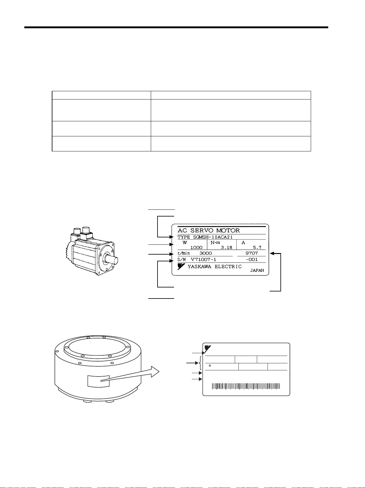
1.1.2 Servomotors
(1) External Appearance and Nameplate Example
(2) Type SGMCS
Check Items Comments
Are the delivered products the ones
that were ordered?
Check the model numbers marked on the nameplates on the
servomotor and SERVOPACK. (Refer to the descriptions of model
numbers in the following section.)
Does the servomotor shaft rotate
smoothly?
The servomotor shaft is normal if it can be turned smoothly by hand.
Servomotors with brakes, however, cannot be turned manually.
Is there any damage? Check the overall appearance, and check for damage or scratches that
may have occurred during shipping.
Manufacturing date
Rated motor speed
Servomotor model
Rated output
Serial number
AC SERVO MOTOR
SGMCS-04C3A11
84
200
2.1
W
V
A
N
200
A
4.0
min
Ins.
O/N 9271316-1
S/N DD9964567890012
YASKAWA ELECTRIC CORPORATION JAPAN
Nameplate
-1
Servomotor model
Ratings
Serial number
Order number
1.2 Product Part Names
1-3
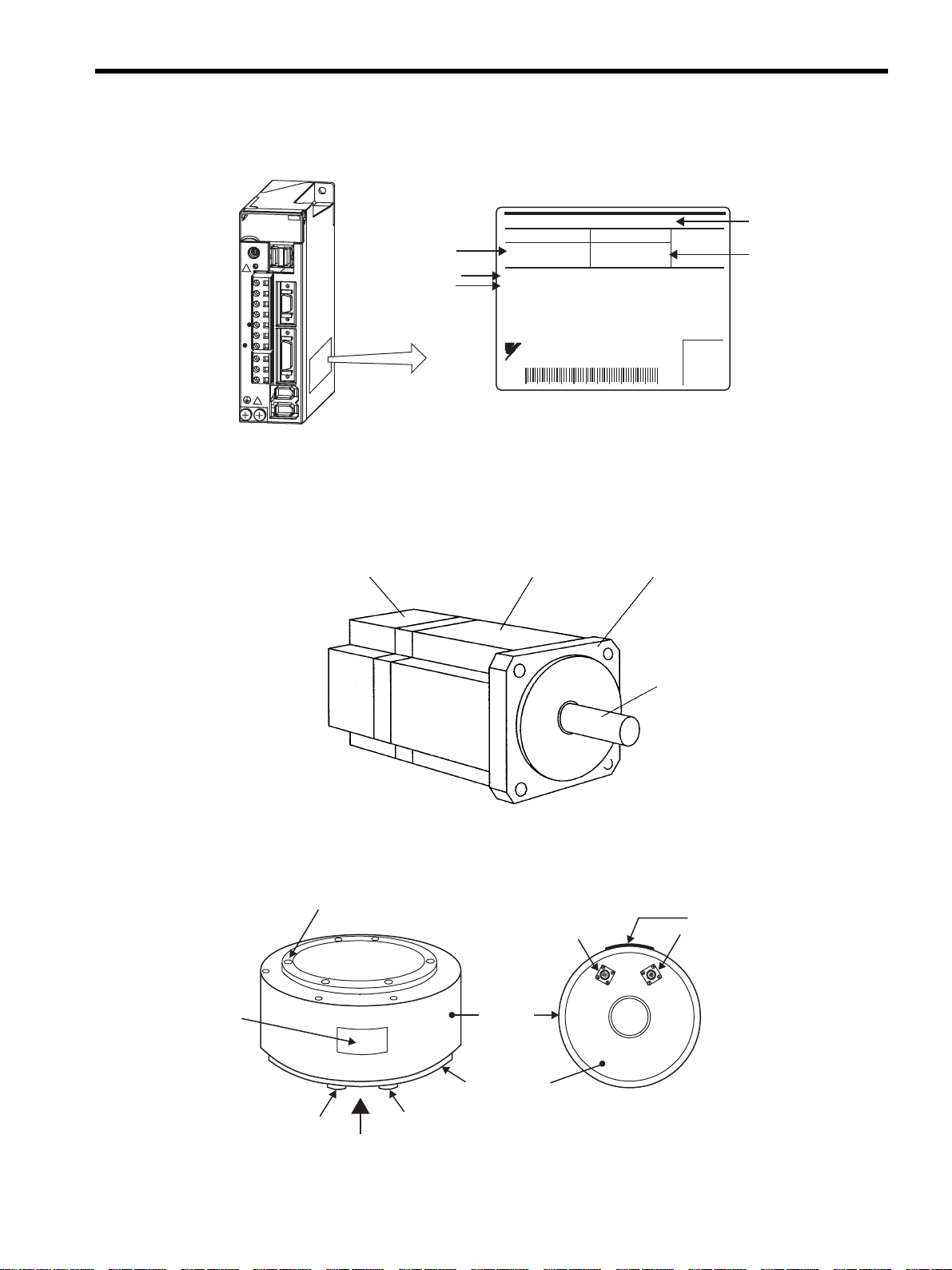
1.1.3 Servo Amplifiers
1.2 Product Part Names
1.2.1 Servomotors
(1) The figure below shows part names for servomotors with or without brakes.
(2) Type SGMCS Direct-drive
Nameplate
YAS
K
AW
A S
ER
VO
PACK
20
0V
SGDS - 02A12A
C
N
3
C
N
6
C
N
1
A/B
C
N
2
C
N
4
S
W
1
C
H
A
R
G
E
L1
L1C
L2C
B1/
B2
U
V
W
L2
SERVOPACK
model
Serial number
Applicable
power supply
Applicable
motor capacity
SGDS-02A12A
AC-OUTPUT
S/N
O/N
AC-INPUT
SERVOPACK MODEL
YASKAWA ELECTRIC
MADE IN JAPAN
1PH 200-230V 50/60Hz 3PH 0-230V 0-300Hz
2.4A 2.1A 200W
60A194-341-7
D001Y3265990007
Order number
Encoder
Frame Flange
Output shaft
Frame
Rotating axis
A
Nameplate
Servomotor connector
Encoder
connector
Mounting
flange
View A
Encoder
connector
Servomotor
connector
Nameplate
1 Outline
1.3.1 Standard Servomotors
1-4
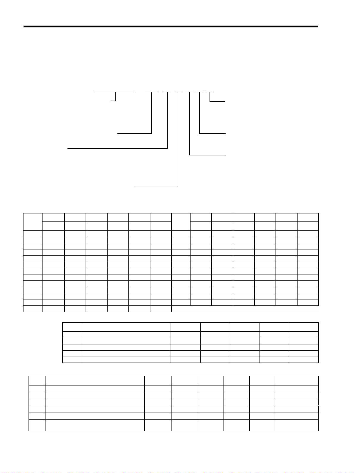
1.3 Model Numbers
1.3.1 Standard Servomotors
Table 1.1: Servomotor Capacity (kW)
Table 1.2: Serial Encoders
Table 1.3: Shaft End Specifications (Straight)
SGMPH - 01 A A A 2 S
Sigma II Series Servomotor Name
SGMAH
SGMPH
SGMGH
SGMSH
A: 200V
B: 100V*
*The only 100V servomotors are the 0.2kW or less
SGMAH and SGMPH models.
Brake and Oil Seal Specifications
1: Standard
S: With oil seal
C: With 24V
DC
brake
E: S + C
Shaft End Specifications
Design Revision Order
A
SGMAH
SGMPH
SGMGH (1500rpm)
SGMSH
SGMPH (IP67 waterproof specification)E:
D: 400V
SGMUH
SGMUH
Power Supply
SGMBH
For AvailableSGMBH: See Catalog for option
s
SGMBH : A = 200% Peak Torque
B = 250% Peak Torque
Servomotor Capacity (See Table 1.1)
Serial Encoder Specifications (See Table 1.2)
(See Table 1.3)
Symbol
SGMAH SGMPH SGMGH SGMSH SGMUH SGBMH
Symbol
SGMAH SGMPH SGMGH SGMSH SGMUH SGMBH
3000rpm 3000rpm 1500rpm 3000rpm 6000rpm 1500rpm 3000rpm 3000rpm 1500rpm 3000rpm 6000rpm 1500rpm
A30.03—————40———4.04.0—
A50.05—————44——4.4———
010.10.1————50———5.0——
020.20.2————55——5.5———
040.40.4————75——7.5———
05——0.45———1A——11———
080.750.75————1E——15———
09——0.85———2B—————22
10———1.01.0—3Z—————30
13——1.3———3G—————37
15—1.5—1.51.5—4E—————45
20——1.82.0——5E—————55
30 — — 2.9 3.0 3.0 —
Code Specification SGMAH SGMPH SGMGH SGMSH SGMUH
1 16-bit absolute encoder Standard Standard — — —
2 17-bit absolute encoder — — Standard Standard Standard
A 13-bit incremental encoder Standard Standard — — —
B 16-bit incremental encoder Optional Optional — — —
C 17-bit incremental encoder — — Standard Standard Standard
Code Specification SGMAH SGMPH SGMGH SGMSH SGMUH SGMBH
2
Straight without key
Optional Optional Optional Optional Optional —
4
Straight with key
Standard Standard — — — Standard
6
Straight with key and tap
Optional Optional Standard Standard Standard Optional
8
Straight with tap
Optional Optional Optional — — —
K
Straight without key, foot mounted
— — — — — Optional
L
Straight with key & tap, foot mounted
— — ———
Optional
(55kW Standard)

1.3 Model Numbers
1-5
1.3.2 Servo Amplifiers
Connecting terminal
For connecting a reactor, refer to 4.4.9 AC/DC Reactors for Power Supplied Designed for Minimum Harmonics.
CN5 Analog monitor connector
Used to monitor motor speed, torque
reference, and other values through
a special cable.
Refer to 4.4.2 Cables for Analog Monitor or
8.7 Analog Monitor.
Indicates the servo status with 7-segment LEDs.
Refer to 10.1.1 Status Display on Panel Operator.
Indicates that the control power is being supplied.
Refer to 10.1.1 Status Display on Panel Operator.
Indicates that data is being transmitted between
the SERVOPACK and the MECHATROLINK-II
system.
Refer to 10.1.1 Status Display on Panel Operator.
Connects MECHATROLINK-II - supported devices.
Refer to 5.4.2 MECHATROLINK-II Communications
Connectors.(CN6A, CN6B)
Refer to 4.4.1 Digital Operator.
Refer to 2.2 SERVOPACK Model
Designations.
Used to set MECHATROLINK-II
communications.
Refer to 6.2 Switches for MECHATROLINK-II
Communications Settings.
Used to set the MECHATROLINK-II
station address.
Refer to 6.2 Switches for MECHATROLINK-II
Communications Settings.
Refer to 5.1 Main Circuit Wiring.
Used to connect external regenerative resistors.
Refer to 5.7 Connecting Regenerative Resistors.
Used for control power supply input.
Refer to 5.1 Main Circuit Wiring.
With the front cover open
Serial number
Charge indicator
Lights when the main circuit power supply is
ON and stays lit as long as the main circuit power
supply capacitor remains charged. Therefore,
do not touch the SERVOPACK even after the power
supply is turned OFF if the indicator is lit.
CN3 Connector for personal computer monitoring
Used to communicate with a personal computer
or to connect a digital operator.
CN1 I/O signal connector
Used for reference input signals and
sequence I/O signals.
Refer to 5.3 Examples of I/O Signal Connection.
CN2 Encoder connector
Connects to the encoder in the SERVOPACK.
Refer to 5.2 Wiring Encoders.
Ground terminal
Be sure to connect to protect against electrical shock.
Main circuit power
supply terminals
Used for main circuit power supply input.
Refer to 5.1 Main Circuit Wiring.
Control power
supply Terminals
Servomotor terminals
Connects to the servomotor power line.
Refer to 5.1 Main Circuit Wiring.
Nameplate (side view)
Indicates the SERVOPACK model and ratings.
Refer to 1.1.3 Nameplate.
SERVOPACK model
Front cover
Regenerative
resistor connecting terminals
Input voltage
CN4 Fully-closed connector
Used to execute the fully-closed control by
scales attached outside the SERVOPACK.
Refer to 9.1 System Configuration for
SERVOPACK with Fully - closed Control.
YASKAWA SERVOPACK
200V
SGDS-02A12A
SW1
CHARGE
L1
L2
L1C
L2C
B1/
B2
U
V
W
C
N
6
C
N
3
C
N
1
C
N
2
C
N
4
A / B
DF0300413 PC
ON
1
POWER
COM
S/N D0024B958810004
LED POWER
Panel display
LED COM
Dip switch (SW2)
MECHATROLINK-II Communications connectors
CN6A CN6B
Rotary switch (SW1)
INFO
1 Outline
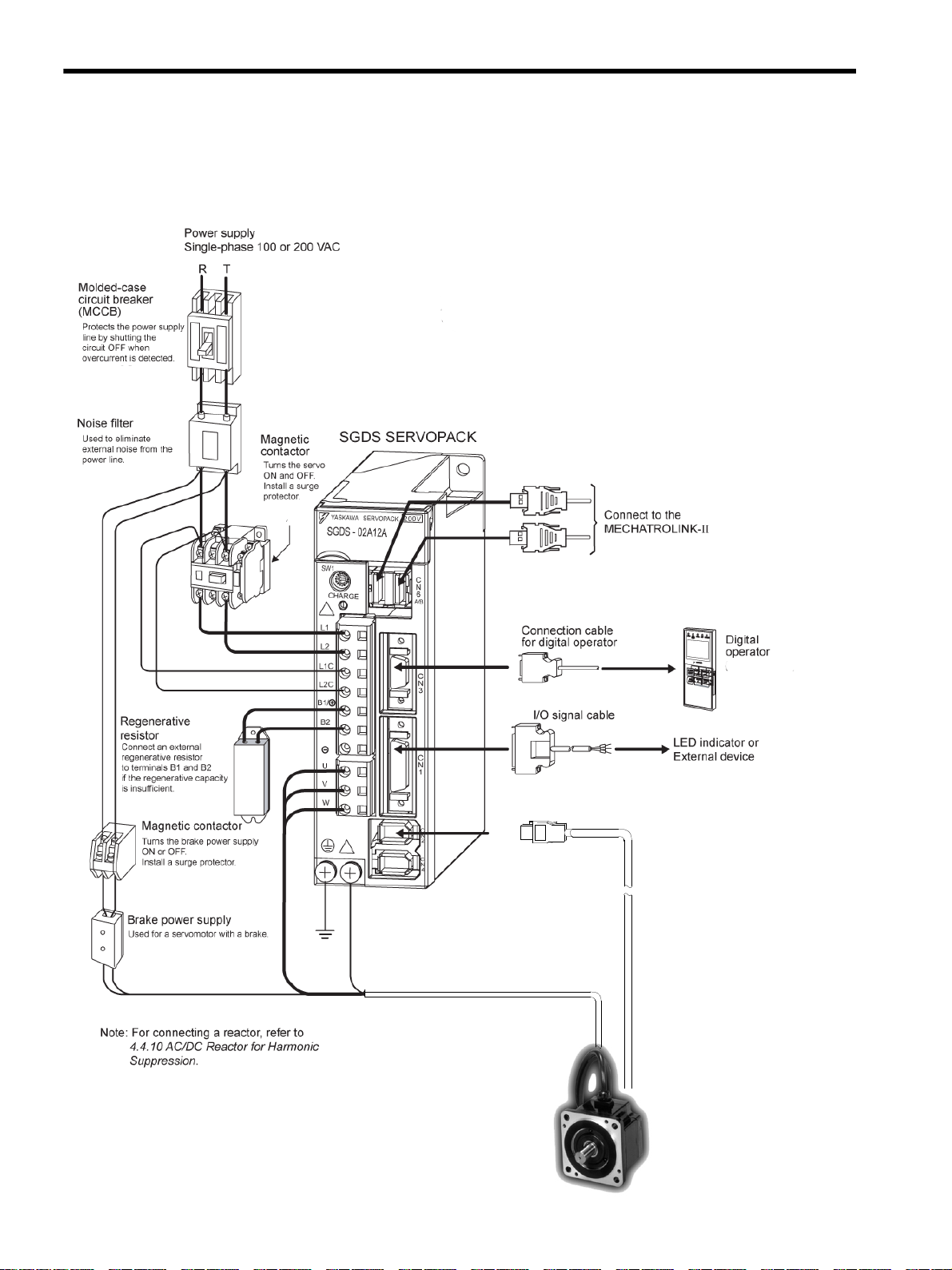
1-6
1.4 Examples of Servo System Configurations
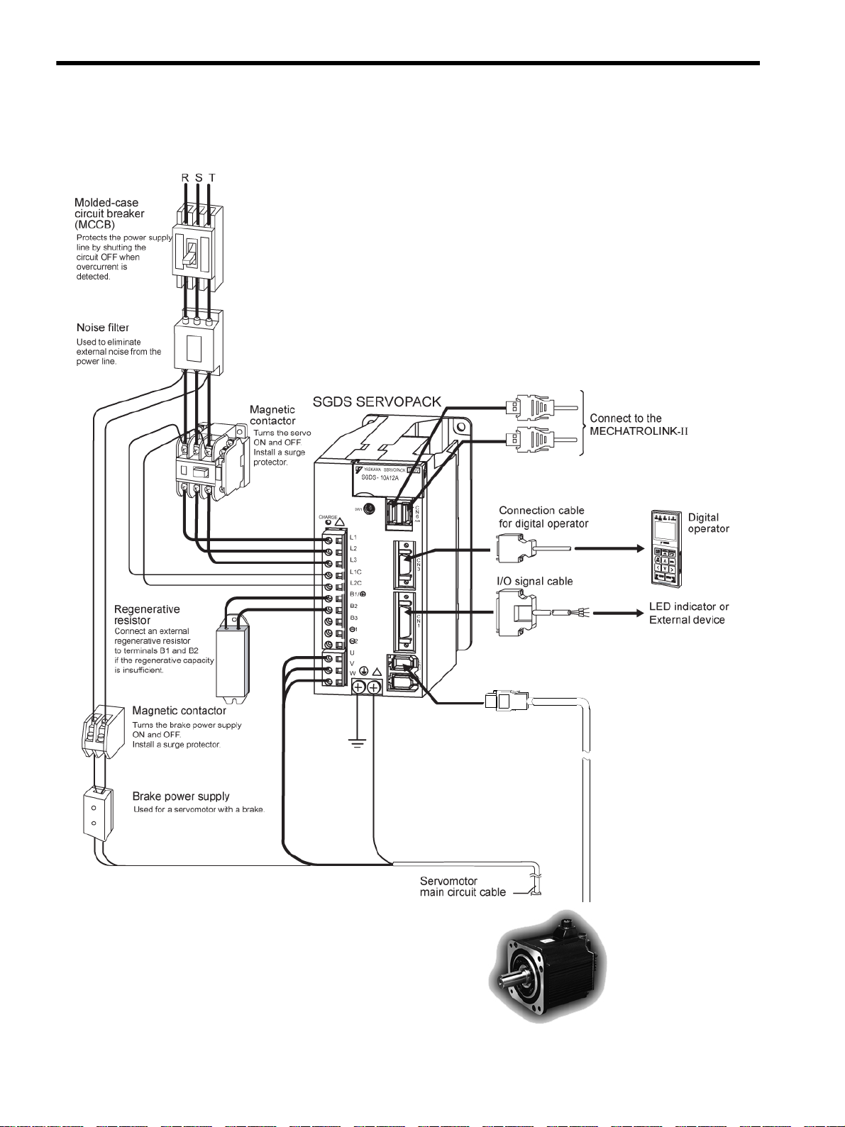
This section describes examples of basic servo system configuration.
(1) Connecting to SGMAH and SGMPH Servomotors

1.4 Examples of Servo System Configurations
1-7
Connect the main circuit cable and encoder cable to SGMAH or SGMPH servomotor in the following manner.
Do not directly touch the connector pins provided with the servomotor. Particularly, the encoder may be
damaged by static electricity, etc.
1. Remove the protective tape and cap from the servomotor connector.
2. Mount the cable connector on the servomotor and fix it with screws as shown in the figure below.
IMPORTANT
1 Outline
1-8
(2) Connecting to SGMSH, SGMGH Servomotors
Power Supply
Three-phase 200VAC
SGMGH
Servomotor
1.4 Examples of Servo System Configurations
1-9
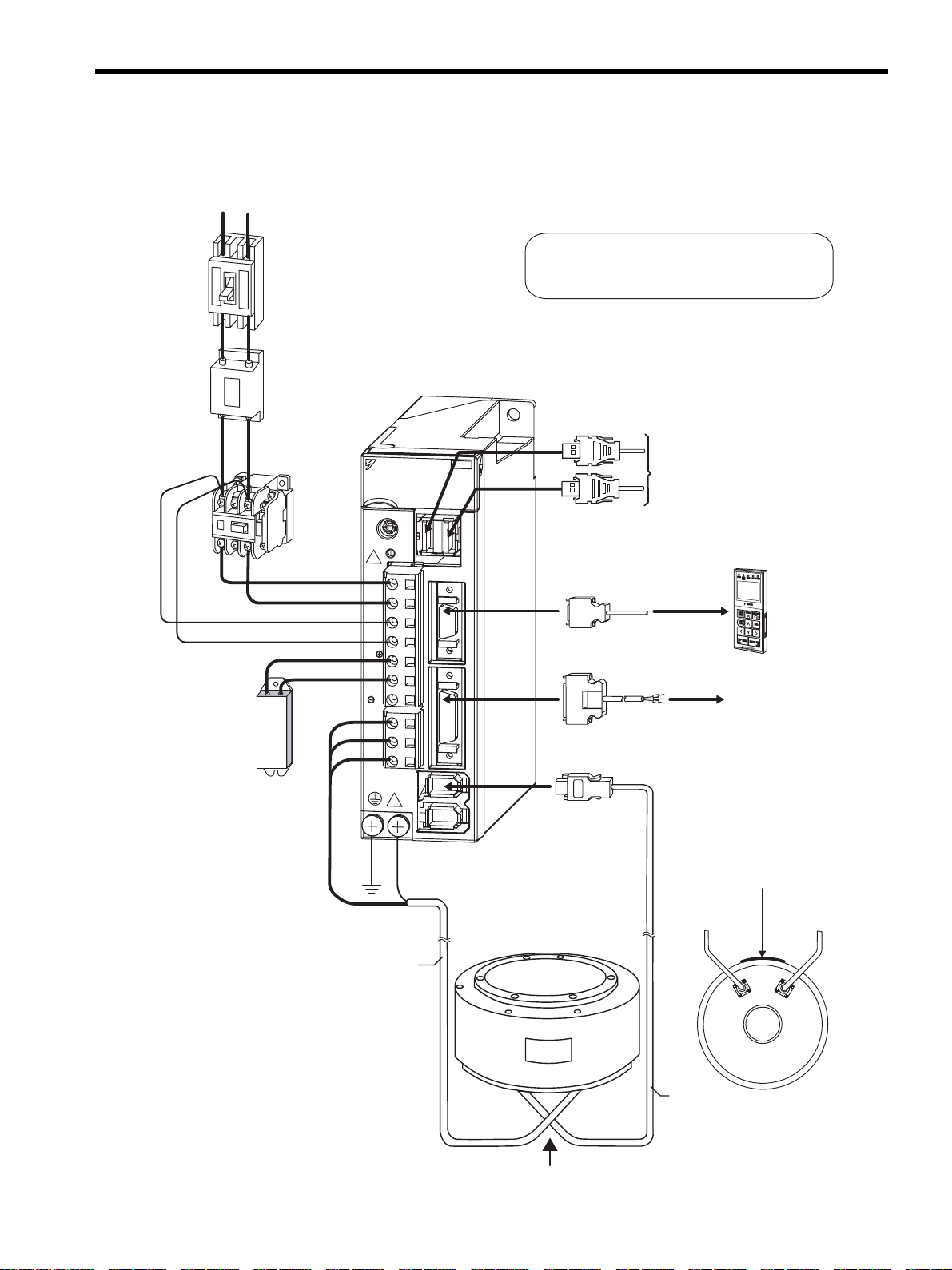
(3) Connecting to SGMCS Servomotor
A
View A
Digital
operator
Connection cable
for digital operator
(Refer to 2.5.1.)
LED indicator or
External device
Note: For connecting a reactor, refer to
5.6.5 AC/DC Reactor for Harmonic
Suppression.
YASKAWA SERVOPACK
200V
SGDS - 02A12A
C
N
3
C
N
6
C
N
1
A/B
C
N
2
C
N
4
SW1
CHARGE
L1
L1C
L2C
B1/
B2
U
V
W
L2
Connect to the
MECHATROLINK-II
Servomotor
main circuit cable
Servomotor
main circuit cable
Encoder
cable
Regenerative
resistor
Noise filter
Molded-case
circuit breaker
(MCCB)
Magnetic
contactor
I/O signal cable
SGDS SERVOPACK
SGMCS Servomotor
Power supply
Single-phase 100 or 200 VAC
R T
Protects the power supply
line by shutting the
circuit OFF when
overcurrent is detected.
(Refer to 2.5.2.)
Used to eliminate
external noise from the
power line.
(Refer to 2.5.3.)
Connect an external
regenerative resistor
to terminals B1 and B2
if the regenerative capacity
is insufficient.
(Refer to 2.5.4.)
Turns the servo
ON and OFF.
Install a surge
protector.
(Refer to
2.5.3.)
Encoder
cable
Nameplate
(Refer to 2.4.3.)
(Refer to 2.4.3.)
Note: Refer to 4.4.10 AC/DC Reactor for Harmonic
Suppression for the connection of AC/DC
reactor Suppression.
1 Outline
1.5.1 North American Safety Standards (UL, CSA)
1-10
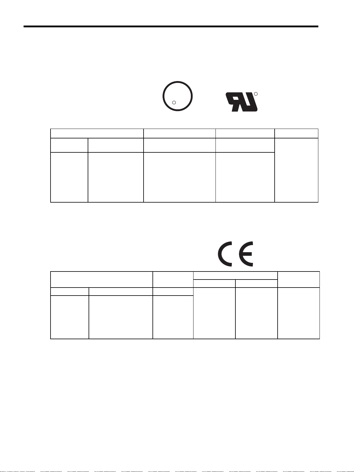
1.5 Applicable Standards
1.5.1 North American Safety Standards (UL, CSA)
* 1. Underwriters Laboratories Inc.
* 2. Canadian Standards Association.
1.5.2 CE Marking
* T
Ü
V Product Services GmbH
Note: Because SERVOPACKs and servomotors are built-in type, reconfirmation is required after
being installed in the final product.
Model
UL
∗1
Standards (UL File No.) CSA
∗2
Standards
Certifications
SERVOPACK
• SGDS-A12A
UL508C (E147823)
CSA C22.2
No.14
UL
Servomotor
• SGMAH
• SGMPH
• SGMSH
• SGMCS-
B,C,D,E
(Available June
2003.)
UL1004 (E165827)
CSA C22.2
No.100
U
L
C
R
US
LISTED
C
R
US
Model
Low Voltage
Directive
EMC Directive
Certifications
EMI EMS
SERVOPACK • SGDS-A12A
EN50178
EN55011
class A group 1
EN61000-6-2
TÜV PS
∗
Servomotor
• SGMAH
• SGMPH
• SGMSH
• SGMCS-M,N
(Available Spetember
2003)
IEC60034-1
IEC60034-5
IEC60034-8
IEC60034-9

2-1
2
System Selection
2.1 Servomotor Model Designations - - - - - - - - - - - - - - - - - - - - - 2-2
2.1.1 Model SGMAH/SGMPH/SGMSH - - - - - - - - - - - - - - - - - - - - - - - - - - 2-2
2.1.2 Model SGMCS - - - - - - - - - - - - - - - - - - - - - - - - - - - - - - - - - - - - - - - 2-4
2.2 SERVOPACK Model Designations - - - - - - - - - - - - - - - - - - - 2-5
2.3 Σ III Series SERVOPACKs and Applicable Servomotors - - - - 2-6
2.4 Selecting Cables - - - - - - - - - - - - - - - - - - - - - - - - - - - - - - - - 2-7
2.4.1 Cables for SGMAH and SGMPH Servomotors - - - - - - - - - - - - - - - - - 2-7
2.4.2 Cables for SGMSH Servomotor - - - - - - - - - - - - - - - - - - - - - - - - - - 2-12
2.4.3 Cables for SGMGH Servomotors - - - - - - - - - - - - - - - - - - - - - - - - - 2-16
2.4.4 Cables for SGMCS Servomotor - - - - - - - - - - - - - - - - - - - - - - - - - - 2-20
2.5 Selecting Peripheral Devices - - - - - - - - - - - - - - - - - - - - - - 2-23
2.5.1 Special Options - - - - - - - - - - - - - - - - - - - - - - - - - - - - - - - - - - - - - - 2-23
2.5.2 Molded-case Circuit Breaker and Fuse Capacity - - - - - - - - - - - - - - - 2-25
2.5.3 Noise Filters, Magnetic Contactors, Surge Protectors
and AC/DC Reactors - - - - - - - - - - - - - - - - - - - - - - - - - - - - - - - - - - 2-22
2.5.4 Regenerative Resistors - - - - - - - - - - - - - - - - - - - - - - - - - - - - - - - - 2-27
Loading...