


 Loading...
YASKAWA
MEMOCON GL120, GL130
HARDWARE USER'S MANUAL
YASKAWA |
MANUAL NO. SIEZ-C825-20.1D |
Manual Contents
This manual describes the hardware specifications and applications of the MEMOCON GL120, GL130.
Please read this manual carefully and be sure you understand the information provided before attempting to install and use the MEMOCON GL120, GL130.
Visual Aids
The following aids are used to indicate certain types of information for easier reference.
. |
Indicates references for additional information. |
|
Indicates important information that should be memorized. |
IMPORTANT |
AEXAMPLE"
INFO |
'SUMMARY
Note
TERMS
Indicates application examples.
Indicates supplemental information.
Indicates a summary of the important points of explanations.
Indicates inputs, operations, and other information required for correct operation but that will not cause damage to the device.
Indicates definitions of terms used in the manual.
NOTICE
The following conventions are used to indicate precautions in this manual. Failure to heed precautions provided in this manual can result in injury to people or damage to the products.
! WARNING Indicates precautions that, if not heeded, could possibly result in loss of life or serious injury.
! Caution Indicates precautions that, if not heeded, could result in relatively serious or minor injury, damage to the product, or faulty operation.
Yaskawa, 2001
All rights reserved. No part of this publication may be reproduced, stored in a retrieval system, or transmitted, in any form, or by any means, mechanical, electronic, photocopying, recording, or otherwise, without the prior written permission of Yaskawa. No patent liability is assumed with respect to the use of the information contained herein. Moreover, because Yaskawa is constantly striving to improve its high-quality products, the information contained in this manual is subject to change without notice. Every precaution has been taken in the preparation of this manual. Nevertheless, Yaskawa assumes no responsibility for errors or omissions. Neither is any liability assumed for damages resulting from the use of the information contained in this publication.
CONTENTS
CHAPTER 1 Introduction and Precautions . . . . . . . . . . . . . . . . . . . . . . . . . . . . |
1-1 |
||
1.1 |
Overview of Manuals . . . . . . . . . . . . . . . . . . . . . . . . . . . . . . . . . . . . . . . . . . . . . . . . . . . . . |
1-2 |
|
1.2 |
Precautions . . . . . . . . . . . . . . . . . . . . . . . . . . . . . . . . . . . . . . . . . . . . . . . . . . . . . . . . . . . . . |
1-7 |
|
|
1.2.1 |
Safety Precautions . . . . . . . . . . . . . . . . . . . . . . . . . . . . . . . . . . . . . . . . . . . . . . . . |
1-7 |
|
1.2.2 |
Installation Precautions . . . . . . . . . . . . . . . . . . . . . . . . . . . . . . . . . . . . . . . . . . . . |
1-8 |
|
1.2.3 |
Removal Precautions . . . . . . . . . . . . . . . . . . . . . . . . . . . . . . . . . . . . . . . . . . . . . . |
1-12 |
|
1.2.4 |
Wiring Precautions . . . . . . . . . . . . . . . . . . . . . . . . . . . . . . . . . . . . . . . . . . . . . . . . |
1-13 |
|
1.2.5 |
Applications Precautions . . . . . . . . . . . . . . . . . . . . . . . . . . . . . . . . . . . . . . . . . . . |
1-16 |
|
1.2.6 |
Maintenance . . . . . . . . . . . . . . . . . . . . . . . . . . . . . . . . . . . . . . . . . . . . . . . . . . . . . |
1-18 |
1.3 |
Using this Manual . . . . . . . . . . . . . . . . . . . . . . . . . . . . . . . . . . . . . . . . . . . . . . . . . . . . . . . . |
1-19 |
|
CHAPTER 2 |
Overview . . . . . . . . . . . . . . . . . . . . . . . . . . . . . . . . . . . . . . . . . . . . . |
2-1 |
|
2.1 Overview of the MEMOCON GL120 and GL130 . . . . . . . . . . . . . . . . . . . . . . . . . . . . . . . |
2-2 |
||
CHAPTER 3 |
System Components . . . . . . . . . . . . . . . . . . . . . . . . . . . . . . . . . . . . |
3-1 |
|
3.1 Overview of System Components . . . . . . . . . . . . . . . . . . . . . . . . . . . . . . . . . . . . . . . . . . . |
3-2 |
||
CHAPTER 4 System Components: Functions and Specifications . . . . . . . . . . |
4-1 |
||
4.1 |
General Specifications . . . . . . . . . . . . . . . . . . . . . . . . . . . . . . . . . . . . . . . . . . . . . . . . . . . . |
4-3 |
|
4.2 |
Power Supply Modules . . . . . . . . . . . . . . . . . . . . . . . . . . . . . . . . . . . . . . . . . . . . . . . . . . . . |
4-4 |
|
|
4.2.1 |
Appearance of Power Supply Modules . . . . . . . . . . . . . . . . . . . . . . . . . . . . . . . . |
4-4 |
|
4.2.2 |
Power Supply Modules: Function and Models . . . . . . . . . . . . . . . . . . . . . . . . . . . |
4-9 |
|
4.2.3 |
Specifications of Power Supply Modules . . . . . . . . . . . . . . . . . . . . . . . . . . . . . . . |
4-10 |
|
4.2.4 |
Selecting Power Supply Modules . . . . . . . . . . . . . . . . . . . . . . . . . . . . . . . . . . . . . |
4-14 |
|
4.2.5 |
Using Power Supply Modules . . . . . . . . . . . . . . . . . . . . . . . . . . . . . . . . . . . . . . . |
4-18 |
4.3 |
CPU Modules . . . . . . . . . . . . . . . . . . . . . . . . . . . . . . . . . . . . . . . . . . . . . . . . . . . . . . . . . . . |
4-24 |
|
|
4.3.1 |
Appearance of CPU Modules . . . . . . . . . . . . . . . . . . . . . . . . . . . . . . . . . . . . . . . . |
4-24 |
|
4.3.2 |
CPU Modules: Functions and Models . . . . . . . . . . . . . . . . . . . . . . . . . . . . . . . . . |
4-30 |
|
4.3.3 |
Specifications of CPU Modules . . . . . . . . . . . . . . . . . . . . . . . . . . . . . . . . . . . . . . |
4-35 |
|
4.3.4 |
Using CPU Modules 1 (For CPU20, CPU30, and CPU35) . . . . . . . . . . . . . . . . . |
4-65 |
|
4.3.5 |
Using CPU Modules 2 (For CPU21) . . . . . . . . . . . . . . . . . . . . . . . . . . . . . . . . . . |
4-80 |
|
4.3.6 |
Using CPU Modules 3 (For CPU10) . . . . . . . . . . . . . . . . . . . . . . . . . . . . . . . . . . |
4-88 |
4.4 |
Communications Modules . . . . . . . . . . . . . . . . . . . . . . . . . . . . . . . . . . . . . . . . . . . . . . . . . |
4-100 |
|
|
4.4.1 |
Models of Communications Modules . . . . . . . . . . . . . . . . . . . . . . . . . . . . . . . . . . |
4-100 |
|
4.4.2 |
Remote I/O Driver Module . . . . . . . . . . . . . . . . . . . . . . . . . . . . . . . . . . . . . . . . . |
4-105 |
|
4.4.3 |
Remote I/O Receiver Module . . . . . . . . . . . . . . . . . . . . . . . . . . . . . . . . . . . . . . . . |
4-111 |
|
4.4.4 |
2000-Series Remote I/O Driver Module . . . . . . . . . . . . . . . . . . . . . . . . . . . . . . . |
4-121 |
|
4.4.5 |
MEMOBUS Modules (RS-232) . . . . . . . . . . . . . . . . . . . . . . . . . . . . . . . . . . . . . . |
4-127 |
|
4.4.6 |
MEMOBUS Modules (RS-422) . . . . . . . . . . . . . . . . . . . . . . . . . . . . . . . . . . . . . . |
4-135 |
|
4.4.7 |
PC Link Module . . . . . . . . . . . . . . . . . . . . . . . . . . . . . . . . . . . . . . . . . . . . . . . . . . |
4-147 |
|
4.4.8 |
Uniwire Interface Module . . . . . . . . . . . . . . . . . . . . . . . . . . . . . . . . . . . . . . . . . . |
4-159 |
|
4.4.9 |
Uniwire H-system Interface Module . . . . . . . . . . . . . . . . . . . . . . . . . . . . . . . . . . |
4-166 |
|
4.4.10 |
Distributed I/O Driver Module . . . . . . . . . . . . . . . . . . . . . . . . . . . . . . . . . . . . . . . |
4-175 |
|
4.4.11 |
M-NET Module . . . . . . . . . . . . . . . . . . . . . . . . . . . . . . . . . . . . . . . . . . . . . . . . . . |
4-182 |
— v —
CONTENTS
|
4.4.12 |
YENET 1600-D Module . . . . . . . . . . . . . . . . . . . . . . . . . . . . . . . . . . . . . . . . . . . |
4-188 |
|
4.4.13 |
Ethernet Interface Module . . . . . . . . . . . . . . . . . . . . . . . . . . . . . . . . . . . . . . . . . . |
4-199 |
|
4.4.14 |
Optical/Electrical Conversion Module . . . . . . . . . . . . . . . . . . . . . . . . . . . . . . . . . |
4-209 |
4.5 |
I/O Modules . . . . . . . . . . . . . . . . . . . . . . . . . . . . . . . . . . . . . . . . . . . . . . . . . . . . . . . . . . . . |
4-218 |
|
|
4.5.1 |
Models of I/O Modules . . . . . . . . . . . . . . . . . . . . . . . . . . . . . . . . . . . . . . . . . . . . |
4-218 |
|
4.5.2 |
Appearance of I/O Modules . . . . . . . . . . . . . . . . . . . . . . . . . . . . . . . . . . . . . . . . . |
4-220 |
|
4.5.3 |
Functions and Specifications of I/O Modules . . . . . . . . . . . . . . . . . . . . . . . . . . . |
4-223 |
|
4.5.4 |
Using I/O Modules . . . . . . . . . . . . . . . . . . . . . . . . . . . . . . . . . . . . . . . . . . . . . . . . |
4-229 |
4.6 |
Special Purpose Modules . . . . . . . . . . . . . . . . . . . . . . . . . . . . . . . . . . . . . . . . . . . . . . . . . . |
4-231 |
|
|
4.6.1 |
Models of Special Purpose Modules . . . . . . . . . . . . . . . . . . . . . . . . . . . . . . . . . . |
4-231 |
|
4.6.2 |
High-speed Counter Module . . . . . . . . . . . . . . . . . . . . . . . . . . . . . . . . . . . . . . . . |
4-233 |
|
4.6.3 |
Pulse Catch Module . . . . . . . . . . . . . . . . . . . . . . . . . . . . . . . . . . . . . . . . . . . . . . . |
4-239 |
4.7 |
Motion Modules . . . . . . . . . . . . . . . . . . . . . . . . . . . . . . . . . . . . . . . . . . . . . . . . . . . . . . . . . |
4-245 |
|
|
4.7.1 |
Models of Motion Modules . . . . . . . . . . . . . . . . . . . . . . . . . . . . . . . . . . . . . . . . . |
4-245 |
|
4.7.2 |
Four-axis Motion Module . . . . . . . . . . . . . . . . . . . . . . . . . . . . . . . . . . . . . . . . . . . |
4-246 |
|
4.7.3 |
One-axis Motion Module . . . . . . . . . . . . . . . . . . . . . . . . . . . . . . . . . . . . . . . . . . . |
4-257 |
|
4.7.4 |
Two-axis Motion Module . . . . . . . . . . . . . . . . . . . . . . . . . . . . . . . . . . . . . . . . . . . |
4-265 |
4.8 |
Other Module . . . . . . . . . . . . . . . . . . . . . . . . . . . . . . . . . . . . . . . . . . . . . . . . . . . . . . . . . . . |
4-277 |
|
|
4.8.1 |
Expander Module . . . . . . . . . . . . . . . . . . . . . . . . . . . . . . . . . . . . . . . . . . . . . . . . . |
4-277 |
|
4.8.2 |
Battery Module . . . . . . . . . . . . . . . . . . . . . . . . . . . . . . . . . . . . . . . . . . . . . . . . . . . |
4-283 |
4.9 |
Mounting Base . . . . . . . . . . . . . . . . . . . . . . . . . . . . . . . . . . . . . . . . . . . . . . . . . . . . . . . . . . |
4-296 |
|
4.10 |
Rack-to-rack I/O Cables . . . . . . . . . . . . . . . . . . . . . . . . . . . . . . . . . . . . . . . . . . . . . . . . . . . |
4-300 |
|
CHAPTER 5 Installation and Wiring . . . . . . . . . . . . . . . . . . . . . . . . . . . . . . . . . |
5-1 |
|
5.1 Designing the Control Panel . . . . . . . . . . . . . . . . . . . . . . . . . . . . . . . . . . . . . . . . . . . . . . . . |
5-2 |
|
5.1.1 |
Structure of Control Panel . . . . . . . . . . . . . . . . . . . . . . . . . . . . . . . . . . . . . . . . . . |
5-2 |
5.1.2 |
Cooling the Control Panel . . . . . . . . . . . . . . . . . . . . . . . . . . . . . . . . . . . . . . . . . . |
5-2 |
5.1.3 |
Preventing Electrical Noise . . . . . . . . . . . . . . . . . . . . . . . . . . . . . . . . . . . . . . . . . |
5-3 |
5.1.4 |
Approximate Masses of Modules and Mounting Bases . . . . . . . . . . . . . . . . . . . . |
5-5 |
5.1.5 |
Maximum Heating Value by Modules . . . . . . . . . . . . . . . . . . . . . . . . . . . . . . . . . |
5-7 |
5.1.6 |
Mounting Base Layout . . . . . . . . . . . . . . . . . . . . . . . . . . . . . . . . . . . . . . . . . . . . . |
5-8 |
5.1.7 |
Module Mounting Dimensions . . . . . . . . . . . . . . . . . . . . . . . . . . . . . . . . . . . . . . . |
5-12 |
5.2 Installing Mounting Bases and Modules . . . . . . . . . . . . . . . . . . . . . . . . . . . . . . . . . . . . . . . |
5-16 |
|
5.2.1 |
Installing Mounting Bases . . . . . . . . . . . . . . . . . . . . . . . . . . . . . . . . . . . . . . . . . . |
5-16 |
5.2.2 |
Installing Modules . . . . . . . . . . . . . . . . . . . . . . . . . . . . . . . . . . . . . . . . . . . . . . . . |
5-20 |
5.2.3 |
Installing the CPU and the Power Supply Module . . . . . . . . . . . . . . . . . . . . . . . . |
5-25 |
5.2.4 |
Installing the Terminal Block for Field Connection Module . . . . . . . . . . . . . . . . |
5-29 |
5.2.5 |
Connector for Field Connections Module . . . . . . . . . . . . . . . . . . . . . . . . . . . . . . |
5-35 |
5.2.6 |
Installing the Communications Modules . . . . . . . . . . . . . . . . . . . . . . . . . . . . . . . |
5-39 |
5.2.7 |
Installing the Motion Module . . . . . . . . . . . . . . . . . . . . . . . . . . . . . . . . . . . . . . . . |
5-44 |
5.2.8 |
Installing Rack-to-Rack I/O Cables . . . . . . . . . . . . . . . . . . . . . . . . . . . . . . . . . . . |
5-49 |
5.3 Panel Wiring . . . . . . . . . . . . . . . . . . . . . . . . . . . . . . . . . . . . . . . . . . . . . . . . . . . . . . . . . . . . |
5-51 |
|
5.3.1 |
Separation of Power Supply Systems . . . . . . . . . . . . . . . . . . . . . . . . . . . . . . . . . . |
5-51 |
5.3.2 |
Wiring the Power Supply Module . . . . . . . . . . . . . . . . . . . . . . . . . . . . . . . . . . . . |
5-51 |
5.3.3 |
Wiring Digital I/O Modules . . . . . . . . . . . . . . . . . . . . . . . . . . . . . . . . . . . . . . . . . |
5-55 |
— vi —
CONTENTS
5.3.4 |
Wiring Other Modules . . . . . . . . . . . . . . . . . . . . . . . . . . . . . . . . . . . . . . . . . . . . . |
5-68 |
5.3.5 |
Grounding . . . . . . . . . . . . . . . . . . . . . . . . . . . . . . . . . . . . . . . . . . . . . . . . . . . . . . . |
5-70 |
5.3.6 |
Hot Swapping . . . . . . . . . . . . . . . . . . . . . . . . . . . . . . . . . . . . . . . . . . . . . . . . . . . . |
5-76 |
5.4 External Wiring . . . . . . . . . . . . . . . . . . . . . . . . . . . . . . . . . . . . . . . . . . . . . . . . . . . . . . . . . . |
5-80 |
|
CHAPTER 6 Low Voltage Directives . . . . . . . . . . . . . . . . . . . . . . . . . . . . . . . . . |
6-1 |
||
6.1 |
Power Supply Modules . . . . . . . . . . . . . . . . . . . . . . . . . . . . . . . . . . . . . . . . . . . . . . . . . . . . |
6-2 |
|
|
6.1.1 |
Models of Power Supply Modules . . . . . . . . . . . . . . . . . . . . . . . . . . . . . . . . . . . . |
6-2 |
|
6.1.2 |
Appearance of Power Supply Modules . . . . . . . . . . . . . . . . . . . . . . . . . . . . . . . . |
6-3 |
|
6.1.3 |
Functions and Specifications of Power Supply Modules . . . . . . . . . . . . . . . . . . . |
6-5 |
|
6.1.4 |
Using Power Supply Modules . . . . . . . . . . . . . . . . . . . . . . . . . . . . . . . . . . . . . . . |
6-6 |
6.2 |
I/O Modules . . . . . . . . . . . . . . . . . . . . . . . . . . . . . . . . . . . . . . . . . . . . . . . . . . . . . . . . . . . . |
6-11 |
|
|
6.2.1 |
Models of I/O Modules . . . . . . . . . . . . . . . . . . . . . . . . . . . . . . . . . . . . . . . . . . . . |
6-11 |
|
6.2.2 |
Appearance of I/O Modules . . . . . . . . . . . . . . . . . . . . . . . . . . . . . . . . . . . . . . . . . |
6-12 |
|
6.2.3 |
EN Standard for I/O Module . . . . . . . . . . . . . . . . . . . . . . . . . . . . . . . . . . . . . . . . |
6-14 |
|
6.2.4 |
Specifications of the I/O Module . . . . . . . . . . . . . . . . . . . . . . . . . . . . . . . . . . . . . |
6-16 |
APPENDICES |
|
|
|
Examples of Panel Layout and Hole Dimensions . . . . . . . . . . . . . . . . . . . . . . . . . . . . . . . . . . . . . |
A-1 |
||
|
A.1 |
Panel Layout . . . . . . . . . . . . . . . . . . . . . . . . . . . . . . . . . . . . . . . . . . . . . . . . . . . . . |
A-2 |
|
A.2 |
Drilling Plan . . . . . . . . . . . . . . . . . . . . . . . . . . . . . . . . . . . . . . . . . . . . . . . . . . . . . |
A-4 |
Dimensions . . |
. . . . . . . . . . . . . . . . . . . . . . . . . . . . . . . . . . . . . . . . . . . . . . . . . . . . . . . . . . . . . . . . |
B-1 |
|
|
B.1 |
Power Supply Modules . . . . . . . . . . . . . . . . . . . . . . . . . . . . . . . . . . . . . . . . . . . . |
B-2 |
|
B.2 |
CPU Modules . . . . . . . . . . . . . . . . . . . . . . . . . . . . . . . . . . . . . . . . . . . . . . . . . . . . |
B-3 |
|
B.3 |
Communications Modules . . . . . . . . . . . . . . . . . . . . . . . . . . . . . . . . . . . . . . . . . . |
B-5 |
|
B.4 |
I/O Modules . . . . . . . . . . . . . . . . . . . . . . . . . . . . . . . . . . . . . . . . . . . . . . . . . . . . . |
B-10 |
|
B.5 |
Special Purpose Modules . . . . . . . . . . . . . . . . . . . . . . . . . . . . . . . . . . . . . . . . . . . |
B-13 |
|
B.6 |
Motion Modules . . . . . . . . . . . . . . . . . . . . . . . . . . . . . . . . . . . . . . . . . . . . . . . . . . |
B-14 |
|
B.7 |
Other Modules . . . . . . . . . . . . . . . . . . . . . . . . . . . . . . . . . . . . . . . . . . . . . . . . . . . |
B-16 |
|
B.8 |
Mounting Bases . . . . . . . . . . . . . . . . . . . . . . . . . . . . . . . . . . . . . . . . . . . . . . . . . . |
B-19 |
|
B.9 |
Cables . . . . . . . . . . . . . . . . . . . . . . . . . . . . . . . . . . . . . . . . . . . . . . . . . . . . . . . . . . |
B-22 |
INDEX
— vii —

Introduction and Precautions |
1 |
|
|
|
|
1
This chapter introduces this manual and provides precautions for the use of this manual and the product. You must read this chapter before attempting to read the rest of the manual or using the product.
1.1 |
Overview of Manuals . . . . . . . . . . . . . . . . . . . . . |
1-2 |
|
1.2 |
Precautions . . . . . . . . . . . . . . . . . . . . . . . . . . . . . |
1-7 |
|
|
1.2.1 |
Safety Precautions . . . . . . . . . . . . . . . . . . . . . . . . . . . . . |
1-7 |
|
1.2.2 |
Installation Precautions . . . . . . . . . . . . . . . . . . . . . . . . . . |
1-8 |
|
1.2.3 |
Removal Precautions . . . . . . . . . . . . . . . . . . . . . . . . . . . |
1-12 |
|
1.2.4 |
Wiring Precautions . . . . . . . . . . . . . . . . . . . . . . . . . . . . . |
1-13 |
|
1.2.5 |
Applications Precautions . . . . . . . . . . . . . . . . . . . . . . . . |
1-16 |
|
1.2.6 |
Maintenance . . . . . . . . . . . . . . . . . . . . . . . . . . . . . . . . . . |
1-18 |
1.3 |
Using this Manual . . . . . . . . . . . . . . . . . . . . . . . |
1-19 |
|
— 1-1 —

Introduction and Precautions
1.1Overview of Manuals
• This manual provides hardware information on the GL120 and GL130 and contains the fol-
|
lowing items. |
||
|
1) |
System configuration |
|
1 |
|||
|
|
||
|
2) |
Types of devices used in the system configuration |
|
|
|||
|
3) |
Functions and specifications of the devices used in the system configuration |
|
|
4) |
Installation and wiring |
|
|
5) |
Examples of panel layout and dimensions for boring |
|
|
6) |
Dimensions |
|
• Read this manual carefully in order to properly use the hardware of the MEMOCON GL120 and GL130 Programmable Controllers. Also, keep this manual in a safe place so that it can be referred to whenever necessary.
• Refer to the following manuals for related peripheral devices, Modules, and software.
— 1-2 —

1.1 Overview of Manuals
Product |
Manual Name |
Manual Number |
|
Content |
|
|
|
|
|
|
|
|
|
CPU |
MEMOCON GL120 |
SIEZ-C825-20.1-1 |
Describes the functions, |
|
|
|
Module |
CPU10 Module |
|
specifications, usage, and ROM |
|
|
|
|
User’s Manual |
|
operation of the CPU10 Module. |
|
|
|
|
MEMOCON GL120 |
SIEZ-C825-20.1-2 |
Describes the functions, |
|
|
|
|
CPU21 Module |
|
specifications, usage, and |
|
|
|
|
User’s Manual |
|
expansion memory access |
|
|
|
|
|
|
instructions of the CPU21 |
|
|
|
|
|
|
Module. |
|
|
|
|
MEMOCON GL120, GL130 |
SIEZ-C825-20.11 |
Describes the following for the |
|
1 |
|
|
Software User’s Manual, |
|
GL120 and GL130: |
|
||
|
Volume 1 |
|
1) |
Operating principles |
|
|
|
|
|
|
|
||
|
|
|
2) |
I/O allocation |
|
|
|
|
|
3) |
Overview of instructions |
|
|
|
|
|
4) |
Instruction processing times |
|
|
|
MEMOCON GL120, GL130 |
SIEZ-C825-20.12 |
Describes the programming |
|
|
|
|
Software User’s Manual, |
|
instructions used to create |
|
|
|
|
Volume 2 |
|
ladder programs for the GL120 |
|
|
|
|
|
|
and GL130. |
|
|
|
|
|
|
The following instructions are |
|
|
|
|
|
|
described in other manuals. |
|
|
|
|
|
|
1) |
Expansion Math Instructions: |
|
|
|
|
|
|
Software User’s Manual (Vol. |
|
|
|
|
|
|
3) |
|
|
|
|
|
2) |
Process Control Instructions: |
|
|
|
|
|
|
Software User’s Manual (Vol. |
|
|
|
|
|
|
4) |
|
|
|
|
|
3) |
CommunIcations Instructions |
|
|
|
|
|
|
COM: |
|
|
|
|
|
|
COM Instructions User’s |
|
|
|
|
|
|
Manual FBUS: |
|
|
|
|
|
|
PC Link Module User’s |
|
|
|
|
|
|
Manual |
|
|
|
|
|
|
MSTR: |
|
|
|
|
|
|
MEMOBUS PLUS User’s |
|
|
|
|
|
|
Manual |
|
|
|
|
|
4) |
Motion Control Instructions |
|
|
|
|
|
|
(ladder motion instructions) |
|
|
|
|
|
|
Motion Module MC20 |
|
|
|
|
|
|
Software User’s Manual |
|
|
|
|
|
5) |
Motion Language |
|
|
|
|
|
|
Motion Module MC20 |
|
|
|
|
|
|
Software User’s Manual |
|
|
|
MEMOCON GL120, GL130 |
SIEZ-C825-20.13 |
Describes expansion math |
|
|
|
|
Software User’s Manual, |
|
instructions (floating point math |
|
|
|
|
Volume 3 |
|
instructions, etc.) used for the |
|
|
|
|
|
|
GL120 and GL130. |
|
|
|
|
MEMOCON GL120, GL130 |
SIEZ-C825-20.14 |
Describes process control |
|
|
|
|
Software User’s Manual, |
|
instructions used for the GL120 |
|
|
|
|
Volume 4 |
|
and GL130. |
|
|
|
I/O |
MEMOCON GL120, GL130 |
SIEZ-C825-20.22 |
Describes the functions, |
|
|
|
Modules |
120-series I/O Modules |
|
specifications, and usage of the |
|
|
|
|
User’s Manual |
|
120-Series Digital I/O Module. |
|
|
|
|
MEMOCON GL120, GL130 |
SIEZ-C825-20.71 |
Describes the functions, |
|
|
|
|
Distributed I/O Module |
|
specifications, and usage of the |
|
|
|
|
User’s Manual |
|
Distributed I/O Module for |
|
|
|
|
(MECHATROLINK) |
|
MECHATROLINK. |
|
|
|
— 1-3 —

Introduction and Precautions
|
|
Product |
Manual Name |
Manual Number |
Content |
|
|
|
|
|
|
|
|
Special |
MEMOCON GL120, GL130 |
SIEZ-C825-20.24 |
Describes the functions, |
|
|
Purpose |
120-series High-speed |
|
specifications, and usage of the |
|
|
Modules |
Counter Module |
|
120-series High-speed Counter |
|
|
|
User’s Manual |
|
Module. |
|
|
|
MEMOCON GL120, GL130 |
SIEZ-C825-20.28 |
Describes the functions, |
|
|
|
Pulse Catch and Counter |
|
specifications, and usage of the |
|
|
|
Module |
|
120-series Pulse Catch and |
|
|
|
User’s Manual |
|
Counter Module. |
1 |
|
|
MEMOCON GL120, GL130 |
SIEZ-C825-20.79 |
Describes the functions, |
|
|
Counter Module |
|
specifications, and usage of the |
|
|
|
|
User’s Manual |
|
Counter Module for |
|
|
|
(MECHATROLINK) |
|
MECHATROLINK. |
|
|
|
|
||
|
|
|
MEMOCON GL120, GL130 |
SIEZ-C825-20.80 |
Describes the functions, |
|
|
|
Pulse Output Module |
|
specifications, and usage of the |
|
|
|
User’s Manual |
|
Pulse Output Module for |
|
|
|
(MECHATROLINK) |
|
MECHATROLINK. |
|
|
Motion |
MEMOCON GL120, GL130 |
SIEZ-C825-20.41 |
Describes the functions, |
|
|
Modules |
Motion Module MC10 |
|
specifications, and usage of the |
|
|
|
User’s Manual |
|
One-axis Motion Module MC10. |
|
|
|
MEMOCON GL120, GL130 |
SIEZ-C825-20.43 |
Describes the functions, |
|
|
|
Motion Module MC15 |
|
specifications, and usage of the |
|
|
|
User’s Manual |
|
Two-axis Motion Module MC15. |
|
|
|
MEMOCON GL120, GL130 |
SIEZ-C825-20.51 |
Describes the functions, |
|
|
|
Motion Module MC20 |
|
specifications, and usage of the |
|
|
|
Hardware User’s Manual |
|
Four-axis Motion Module MC20. |
|
|
|
MEMOCON GL120, GL130 |
SIEZ-C825-20.52 |
Describes motion control |
|
|
|
Motion Module MC20 |
|
instructions (ladder motion |
|
|
|
Software User’s Manual |
|
instructions) and motion program |
|
|
|
|
|
language used for the Four-axis |
|
|
|
|
|
Motion Module MC20. |
|
|
|
MEMOCON GL120, GL130 |
SIEZ-C825-60.3 |
Describes the functions, |
|
|
|
Teach Pendant TB120 for |
|
specifications, and usage of the |
|
|
|
Motion Module MC20 |
|
Teach Pendant TB120. |
|
|
|
User’s Manual |
|
|
|
|
Human- |
MEMOCON GL120, GL130 |
SIEZ-C825-60.7 |
Describes the functions, |
|
|
Machine |
MEMOSOFT for P120 |
|
specifications, and usage of the |
|
|
Interface |
Programming Panel |
|
Programming Panel P120 (with |
|
|
|
User’s Manual |
|
built-in MEMOSOFT). |
|
|
|
MEMOCON GL120, GL130 |
SIEZ-C825-60.10 |
Describes the functions and |
|
|
|
MEMOSOFT |
|
usage of the MEMOSOFT for |
|
|
|
User’s Manual |
|
DOS. |
|
|
|
MEMOCON GL120, GL130 |
SIEZ-C825-60.25 |
Describes the functions and |
|
|
|
MEMOSOFT for Windows |
|
usage of the MEMOSOFT for |
|
|
|
User’s Manual |
|
Windows. |
|
|
|
MEMOCON GL120, GL130 |
SIEZ-C825-60.19 |
Describes the functions, |
|
|
|
Online Programmer for |
|
specifications, and usage of the |
|
|
|
P120 Programming Panel |
|
Online Programmer for the |
|
|
|
User’s Manual |
|
GL120 and GL130. |
|
|
|
MEMOCON GL120, GL130 |
SIEZ-C825-60.19-2 |
Describes the functions, |
|
|
|
MEMOMAIL for P120 |
|
specifications, and usage of the |
|
|
|
Programming Panel |
|
Online Programmer MEMOMAIL |
|
|
|
User’s Manual |
|
for the GL120 and GL130. |
|
|
|
MEMOCON GL120, GL130 |
SIEZ-C825-60.22 |
Describes the functions, |
|
|
|
Online Programmer for |
|
specifications, and usage of the |
|
|
|
P140 Programming Panel |
|
Online Programmer for the |
|
|
|
User’s Manual |
|
GL120 and GL130. |
|
|
|
FA Monitor for MEMOCON |
SIE-C825-60.57 |
Describes the functions, |
|
|
|
Series ACGC4200 |
|
specifications and usage of the |
|
|
|
User’s Manual |
|
FA Monitors ACGC4250/4260. |
— 1-4 —

1.1 Overview of Manuals
Product |
Manual Name |
Manual Number |
Content |
|
|
|
|
|
|
|
|
Commu- |
MEMOCON GL120, GL130 |
SIEZ-C825-70.4 |
Describes the functions, |
|
|
nication |
PC Link Module |
|
specifications, and usage of the |
|
|
Modules |
User’s Manual |
|
PC Link Module for the GL120 |
|
|
|
|
|
and GL130. |
|
|
|
MEMOCON GL120, GL130 |
SIEZ-C825-70.5 |
Describes the functions, |
|
|
|
MEMOBUS PLUS |
|
specifications, and usage of the |
|
|
|
User’s Manual |
|
MEMOBUS PLUS. |
|
|
|
MEMOCON GL120, GL130 |
SIEZ-C825-70.6 |
Describes the SA85 Network |
|
|
|
MEMOBUS PLUS |
|
Adapter for the MEMOBUS |
|
1 |
|
SA85 Network Adapter |
|
PLUS. |
|
|
|
User’s Manual |
|
|
|
|
|
MEMOCON GL120, GL130 |
SIEZ-C825-70.7 |
Describes the BM85 |
|
|
|
MEMOBUS PLUS |
|
Bridge/Multiplexer for the |
|
|
|
BM85 Bridge/Multiplexer |
|
MEMOBUS PLUS. |
|
|
|
User’s Manual |
|
|
|
|
|
MEMOCON GL120, GL130 |
SIEZ-C825-70.8 |
Describes the functions, |
|
|
|
Coaxial Remote I/O System |
|
specifications, and usage of the |
|
|
|
User’s Manual |
|
Coaxial Remote I/O System for |
|
|
|
|
|
the GL120 and GL130. |
|
|
|
1000/2000-Series Coaxial |
SIEZ-C825-70.9 |
Describes the functions, |
|
|
|
Remote I/O System |
|
specifications, and usage of the |
|
|
|
User’s Manual |
|
Coaxial Remote I/O System for |
|
|
|
|
|
the GL120 and GL130 using |
|
|
|
|
|
1000 I/O and 2000 I/O |
|
|
|
MEMOCON GL120, GL130 |
SIEZ-C825-20.26 |
Describes the functions, |
|
|
|
Uniwire Interface Module |
|
specifications, and usage of the |
|
|
|
User’s Manual |
|
120-series Uniwire Interface |
|
|
|
|
|
Module. |
|
|
|
MEMOCON GL120, GL130 |
SIEZC82052100 |
Describes the functions, |
|
|
|
Uniwire H-system Interface |
|
specifications, and usage of the |
|
|
|
Module |
|
120-series Uniwire Interface |
|
|
|
User’s Manual |
|
Module. |
|
|
|
MEMOCON GL120, GL130 |
SIEZ-C825-20.29 |
Describes the functions, |
|
|
|
Distributed I/O Driver |
|
specifications, and usage of the |
|
|
|
Module |
|
120-series Distributed I/O Driver |
|
|
|
User’s Manual |
|
Module for MECHATROLINK. |
|
|
|
MEMOCON GL120, GL130 |
SIEZ-C825-70.12 |
Describes the functions, |
|
|
|
M-NET Module |
|
specifications, and usage of the |
|
|
|
User’s Manual |
|
M-NET Module. |
|
|
|
MEMOCON GL120, GL130 |
SIEZ-C825-70.13 |
Describes the functions, |
|
|
|
MEMOBUS |
|
specifications, and usage of the |
|
|
|
User’s Manual |
|
MEMOBUS. |
|
|
|
MEMOCON GL120, GL130 |
SIEZ-C825-70.14 |
Describes the functions, |
|
|
|
COM Instructions |
|
specifications, and usage of the |
|
|
|
User’s Manual |
|
COM instructions. It also |
|
|
|
|
|
describes the specifications and |
|
|
|
|
|
usage of the MEMOBUS |
|
|
|
|
|
Module. |
|
|
|
MEMOCON GL120, GL130 |
SIEZ-C825-70.18 |
Describes the functions, |
|
|
|
Optical/Electrical |
|
specifications, and usage of the |
|
|
|
Conversion Module |
|
Optical/Electrical Conversion |
|
|
|
User’s Manual |
|
Module. |
|
|
|
MEMOCON GL120, GL130 |
SIEZ-C825-70.20 |
Describes the functions, |
|
|
|
YENET 1600-D Module |
|
specifications, and usage of the |
|
|
|
User’s Manual |
|
YENET 1600-D Module. |
|
|
|
MEMOCON GL120, GL130 |
SIEZ-C825-70.21 |
Describes the functions, |
|
|
|
Ethernet Interface Module |
|
specifications, and usage of the |
|
|
|
User’s Manual |
|
Ethernet Interface Module. |
|
|
— 1-5 —
Introduction and Precautions
|
|
Product |
Manual Name |
Manual Number |
Content |
|
|
|
|
|
|
|
|
Commu- |
MEMOCON GL120, GL130 |
SIEZ-C825-70.22 |
Describes the functions, |
|
|
nication |
FIX Ethernet MEMOBUS |
|
specifications, and usage of the |
|
|
Modules |
Driver (YME) |
|
FIX Ethernet MEMOBUS Driver. |
|
|
|
User’s Manual |
|
|
|
|
Other |
MEMOCON GL120, GL130 |
SIEZ-C825-60.10-4 |
Describes the functions, |
|
|
Products |
Traceback |
|
specifications, and usage of the |
|
|
|
User’s Manual |
|
Traceback. |
|
|
• Thoroughly check the specifications and conditions or restrictions of the product before |
|||
1 |
|
||||
|
use. |
|
|
|
|
|
|
|
|
|
|
— 1-6 —

1.2 Precautions
1.2Precautions
This section outlines general precautions that apply to using this manual and the product. You must read this section first before reading the remainder of the manual.
1.2.1 |
Safety Precautions |
1-7 |
1 |
|
|||
1.2.2 |
. . . . . . . . . . . . . . . . . . . . . . . . . . . . . . . . . . . . . . . . . . .Installation Precautions |
1-8 |
|
1.2.3 |
Removal Precautions . . . . . . . . . . . . . . . . . . . . . . . . . . . . . . . . . . . . . . . . . . . . |
1-12 |
|
1.2.4 |
Wiring Precautions . . . . . . . . . . . . . . . . . . . . . . . . . . . . . . . . . . . . . . . . . . . . . . . |
1-13 |
|
1.2.5 |
Applications Precautions . . . . . . . . . . . . . . . . . . . . . . . . . . . . . . . . . . . . . . . . . . |
1-16 |
|
1.2.6 |
Maintenance . . . . . . . . . . . . . . . . . . . . . . . . . . . . . . . . . . . . . . . . . . . . . . . . . . . . |
1-18 |
|
1.2.1Safety Precautions
•The GL120 and GL130 were not designed or manufactured for use in devices or systems directly related to human life. Users who intend to use the product described in this manual for special purposes such as devices or systems relating to transportation, medical, space aviation, atomic power control, or underwater use must contact Yaskawa Electric Corporation beforehand.
•This product has been manufactured under strict quality control guidelines. However, if this product is to be installed in any location in which a failure of GL120 and GL130 involves a life and death situation or in a facility where failure may cause a serious accident, safety devices MUST be installed to minimize the likelihood of any accident.
•Any illustrations, photographs, or examples used in this manual are provided as examples only and may not apply to all product to which this manual is applicable.
•The products and specifications described in this manual or the content and presentation of the manual may be changed without notice to improve the product and/or the manual. A new version of the manual will be released under a revised manual number when any changes are made.
•Contact your Yaskawa representative or a Yaskawa office listed on the back of this manual to order a new manual whenever this manual is damaged or lost. Please provide the manual number listed on the front cover of this manual when ordering.
•Contact your Yaskawa representative or a Yaskawa office listed on the back of this manual to order new nameplates whenever a nameplate becomes worn or damaged.
•Yaskawa cannot guarantee the quality of any products which have been modified. Yaskawa assumes no responsibility for any injury or damage caused by a modified product.
—1-7 —
Introduction and Precautions
1.2.2Installation Precautions
1.2.2Installation Precautions
|
Abide by the following precautions when installing GL120 and GL130 systems. |
|
! Caution The installation environment must meet the environmental conditions given in product cata- |
|
logs and manuals. Using the GL120 and GL130 in environments subject to high tempera- |
|
tures, high humidity, excessive dust, corrosive gases, vibration, or shock can lead to electri- |
|
cal shock, fire, or faulty operation. Do not use the GL120 and GL130 in the following locations. |
|
|
1 |
• Locations subject to direct sunlight or ambient temperatures not between 0 and 60 _C. |
•Locations subject to relative humidity in excess of 95%, or condensation because of rapid changes in humidity.
•Locations subject to corrosive or flammable gas.
•Locations that would subject the GL120 and GL130 to direct vibration or shock.
•Locations subject to contact with water, oil, chemicals, etc.
!Caution Install the GL120 and GL130 as described in this product manual. Improper installation can
cause product failure, malfunctions, or Modules or other components to fall off.
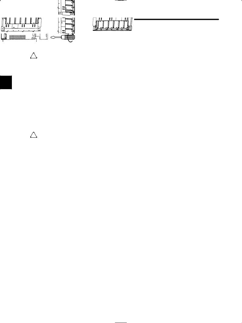
1)Make sure that all mounting screws are securely tightened.
Make sure that all installation screws for Modules or terminal block for field connection are securely tightened so that they do not become loose. Loose screws will cause failures in the GL120 and GL130.
Power
Supply
Module
Module mounting screw
2)Install Mounting Bases in the correct direction. Faulty or inappropriate installation may result in detachment, failure, or malfunction.
Module hooks
Install Mounting Base perpendicularly so that the Module hooks face upwards.
— 1-8 —

1.2 Precautions
! Caution Never install a Mounting Base on the DIN track when transporting over long distances or when the control panel which houses the GL120 or GL130 will be used in an environment subject to excessive vibration. In such cases, install the Mounting Base directly onto a steel
installation plate. |
|
If the Mounting Base is installed on DIN track, it may fall off if subject to strong shock or |
|
vibration. |
|
|
|
! Caution Connector covers are attached to the Module connectors on the Mounting Base. Leave the |
1 |
Module connectors attached to the connector covers when mounting the Mounting Base so |
|
that foreign matter does not enter the Module connectors during mounting operations. |
|
The GL120 and GL130 may malfunction if any foreign matter enters a Module connector. |
|
! Caution When installing the Power Supply Module, turn OFF the power supply to the field wiring termi- |
|
nals. |
|
Installing the Power Supply Module while the power is being supplied may damage the |
|
Module or cause malfunction of the GL120 and GL130. |
|
! Caution When installing the CPU or the Expander Module, turn OFF the power supply to all Power |
|
Supply Modules. |
|
Installing the CPU or the Expander Module while the power is being supplied to Power |
|
Supply Modules may damage the Module or cause malfunction of the GL120 and GL130. |
|
! Caution When installing the terminal block for the AC I/O Modules, turn OFF the AC power supply to |
|
the AC I/O Modules for input signal or driving loads. |
|
Installing a terminal block with AC power to the external power supply terminal of the AC |
|
I/O Modules may cause an electric shock at touching the power supply terminals. |
|
! Caution Make sure that all mounting screws for the terminal block are securely tightened. |
|
Make sure that all mounting screws for the terminal block are securely tightened so that |
|
they do not become loose. Loose screws may cause malfunctioning of the GL120, |
|
GL130. |
|
! Caution Male sure that all cable connectors for the Module are securely inserted and tightened. |
|
Insufficient insertion and/or looseness may cause malfunction of the GL120 and GL130. |
|
— 1-9 —

Introduction and Precautions
1.2.2 Installation Precautions cont.
! Caution Mount the Modules mentioned in the table below on CPU racks (racks with CPU Modules).
Mounting these Modules on any other racks may damage the Modules or cause a malfunction of the GL120 and GL130.
|
|
Modules to be Mounted on CPU Rack |
Model No. |
|
|
|
|
|
|
Remote I/O Driver Module |
JAMSC-120CDR13100 |
|
|
|
|
|
|
2000-series Remote I/O Driver Module |
JAMSC-120CDR13110 |
1 |
|
||
|
|
|
|
PC Link Module |
JAMSC-120NFB23100 |
||
|
|
Ethernet Interface Module |
JAMSC-120NET12100 |
|
|
! Caution Mount the Modules mentioned in the table below on local channel racks.
Mounting these Modules on remote channel racks may damage the Modules or cause a malfunction of the GL120 and GL130.
Modules to be Mounted on Local Channel Rack |
Model No. |
|
|
MEMOBUS Module (RS-232) |
JAMSC-120NOM13100 |
|
|
MEMOBUS Module(RS-422) |
JAMSC-120NOM13110 |
! Caution When installing the Modules that do not support hot swapping, turn OFF the power supply to Power Supply Modules.
Installing the Modules that do not support hot swapping while the power is being supplied to Power Supply Modules may damage the Module or cause malfunction of the GL120 and GL130.
Modules that Do Not Support Hot Swapping |
Model No. |
|
|
Remote I/O Driver Module |
JAMSC-120CDR13100 |
|
|
2000-series Remote I/O Driver Module |
JAMSC-120CDR13110 |
! Caution When connecting the cables connected to the Ethernet Interface Modules, turn OFF the power supply to the Power Supply Modules on the racks where the Ethernet Interface Modules are mounted.
Connecting the cables while power is being supplied to the Power Supply Modules may damage the Ethernet Interface Module or cause a malfunction of the GL120 and GL130.
! Caution Mount the MC20 Module on a CPU Rack(a rack with CPU Module).
Installing the MC20 Module on any other rack may damage the Module or cause the malfunction of the GL120 and GL130.
! Caution When using the absolute position detecting function with the MC15 Module, it must be mounted on the CPU Rack (a rack with CPU Module).
Installing the MC15 Module on any other rack may damage the Module or cause the malfunction of the GL120 and GL130.
— 1-10 —

1.2 Precautions
! Caution When installing the Motion Module, turn OFF the power supply to the Power Supply Module on the rack with the Motion Module mounted.
Installing the Motion Module while the power is being supplied to the Power Supply Module may damage the Module or cause malfunction of the GL120 and GL130.
! Caution When connecting the cables to the Motion Module, turn OFF the power supply to the Power Supply Module on the rack with the Motion Module mounted.
1
Connecting cables to a Motion Module while the power is being supplied may damage the Module or cause malfunction of the GL120 and GL130.
! Caution When connecting the Rack-to-rack I/O cables to the Motion Module, turn OFF the power Supply to all Power Supply Modules.
Connecting the cables while the power while the power is being supplied may damage the Module or cause a malfunction of the GL120 and GL130.
! Caution The total length of the rack-to rack I/O cable for each station is always 6.0 m or less.
If the total length of the cables exceeds 6.0 m, operational errors may occur at the station.
! Caution Make sure that all cable connectors for the Module are securely inserted and tightened.
Insufficient insertion and/or looseness may cause malfunction of the GL120 and GL130.
! Caution Do not remove the connector covers from the Module connectors on the Mounting Base slots where no Modules are installed.
The GL120 and GL130 may malfunction if any foreign matter enters a Modules connector.
! Caution Make sure that all mounting screws for the Module are securely tightened.
Make sure that all mounting screws for the Modules are securely tightened so that they do not become loose. Loose screws may cause malfunction of the GL120 and GL130.
! Caution Do not mount more than one Power Supply Modules on a single Mounting Base.
Mounting more than one Power Supply Modules on a single Mounting Base may damage the Power Supply Module and cause malfunction of the GL120 and GL130.
! Caution Do not mount more than CPU Modules and Expander Module on a single Mounting Base.
Mounting more than CPU Modules and Expander Module on a single Mounting Base may damage the CPU Modules and Expander Module or cause malfunction of the GL120 and GL130.
— 1-11 —

Introduction and Precautions
1.2.3 Removal Precautions
1.2.3Removal Precautions
!Caution Always turn OFF the power to field wiring terminals before removing the Power Supply Mod-
ule.
Removing the Power Supply Module while power is supplied to field wiring terminals may damage the Power Supply Module or cause malfunction of the GL120 and GL130.
1 |
! Caution Always turn OFF the power to the Power Supply Module before removing the CPU Modules |
|
or Expander Module. |
Removing the CPU Modules and Expander Module while power is supplied to Power Supply Module may damage the CPU Modules and Expander Module or cause malfunction of the GL120 and GL130.
! Caution Always turn OFF the AC power supply to the AC I/O Modules for inputting signal or for driving loads before removing the terminal block from the AC I/O Modules.
Removing a terminal block with AC power supply to the external power supply terminal of the AC I/O Modules may cause an electric shock at touching the power supply terminals.
! Caution When inserting or removing an AC I/O Module while the AC power supply is turned ON, install a safety switch for each Module and always turn this safety switch OFF to turn OFF the AC power supply to the Module.
Inserting or removing an AC I/O Module while the AC power supply is being supplied may result in an electric shock at touching the power supply terminals.
! Caution Always turn OFF the power to the Power Supply Module before removing the Modules that do not support hot swapping.
Removing the Modules that do not support hot swapping while the power is being supplied to the Power Supply Module may damage the Modules or cause a malfunction of the GL120 and GL130.
Modules that Do Not Support Hot Swapping |
Model No. |
|
|
Remote I/O Driver Module |
JAMSC-120CDR13100 |
|
|
2000-series Remote I/O Driver Module |
JAMSC-120CDR13110 |
! Caution Always turn OFF the power to Power Supply Modules on the rack having the Ethernet I/F Module Mounted, before removing the cables connected to the Ethernet I/F Module.
Removing cables connected to the Ethernet I/F Module while power is being supplied to
Power Supply Module may damage the Modules or cause malfunction of the GL120 and
GL130.
— 1-12 —
1.2 Precautions
! Caution Always turn OFF the power to Power Supply Module on the Rack, having the Motion Module mounted, control power of Servo Amp, and power supply for the external I/O devices, before removing cables to the Motion Module.
Removing cables connected to the Motion Module while power is being supplied to these devices may damage the Motion Module or cause malfunction of the GL120 and GL130.
! Caution Always turn OFF the power to Power Supply Module on the rack, having the Motion Module mounted, control power of Servo Amp, and power supply for the external I/O devices before 1 removing the Motion Module.
Removing the Motion Module while the power is being supplied to these devices may damage the Motion Module or cause malfunction of the GL120 and GL130.
! Caution Always turn OFF the power to Power Supply Module before removing the Rack−to rack I/O cables connected to the Expander Module.
Removing cables connected to the Expander Module while power is being supplied to Power Supply Module may damage the Expander Module or cause malfunction of the GL120 and GL130.
1.2.4Wiring Precautions
!Caution Connect the correct power supply for the required ratings.
Connecting unsuitable power supplies may result in fires.
! Caution Wiring must be performed by qualified personnel.
Wrong or inappropriate wiring may result in fire, product failure, or electric shock.
! Caution Wire power supply wires to the DC Power Supply Module with the correct polarity.
Wiring with incorrect polarity may result in damage to the DC Power Supply Module.
! Caution Connect power supplies of the same phases to the common 1 and common 2 of the AC I/O Module.
If power supplies of different phases are connect, overheating or fire may occur.
— 1-13 —

Introduction and Precautions
1.2.4 Wiring Precautions cont.
! Caution When inserting or removing an AC I/O Modules while the AC power supply is turned ON, install a safety switch for each Module and always turn this safety switch OFF to turn OFF the AC power supply to the Module.
Inserting or removing an AC I/O Modules while the AC power supply is being supplied may result in an electric shock at touching power supply terminals.
|
! |
Caution When using one of the following Output Modules, connect an external fuse corresponding to |
|
1 |
|||
|
the specifications of the load and in series with the load. |
||
|
|
|
a) 100/200-VAC 8-point Output Module (Model No.: JAMSC-120DAO83000) (Model No.: JAMSC-120DAO83009)
b) 100/200-VAC 16-point Output Module (Model No.: JAMSC-120DAO84300) (Model No.: JAMSC-120DAO84309)
c)12/24-VDC 16-point Output Module (sinking) (Model No.: JAMSC-120DDO34310)
d)12/24-VDC 16-point Output Module (sourcing) (Model No.: JAMSC-120DDO34320)
e)12/24-VDC 32-point Output Module (sinking) (Model No.: JAMSC-120DDO35410)
f)12/24-VDC 64-point Output Module (sinking) (Model No.: JAMSC-120DDO36410)
g)Relay Contact 16-point Output Module (Model No.: JAMSC-120DRA84300)
(Model No.: JAMSC-120DRA84309)
Not connecting an external fuse may result in fire, damage to the device, or damage to output circuit due to an overload or a short-circuit at the load.
! Caution Ground the protective ground terminal to a resistance of 100 Ω max.
Not grounding the protective ground terminal may result in electric shock or malfunction.
Insert the Interface Cables Properly
•Insert the connectors of the various interface cables that are to be connected to GL120 and GL130 into the communication ports and secure them properly.
Improper insertion of interface cables may cause operational errors in the GL120 and
GL130.
— 1-14 —
1.2 Precautions
Power Supply Noise Reduction
•Prevent noise from penetrating into the product by installing an isolation transformer or a noise filter for the external power supply.
Noise from power supply may result in the malfunctioning of GL120 and GL130.
Select, Separate, and Lay External Wiring Correctly |
1 |
|
•I/O lines connecting external devices to the 120-series I/O Modules must be selected based on the following considerations: mechanical strength, resistance to noise, wiring distance, signal voltage, etc.
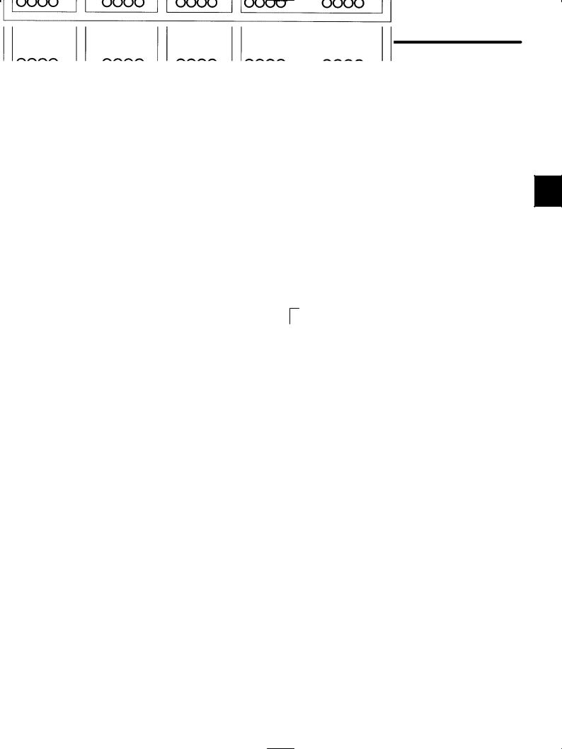
•I/O lines must be separated from power lines both inside and outside the control panel to minimize the affects of noise. Faulty operation may result if I/O lines are not sufficiently separated from power lines.
Control panel separator
Example of external wiring separation
Power lines |
General control |
Digital I/O |
Analog I/O |
Pulse input |
|
circuit cables |
signal cables |
signal cables |
signal cables |
— 1-15 —
Introduction and Precautions
1.2.5 Applications Precautions
1.2.5Applications Precautions
!WARNING Do not touch terminals while the power is ON.
Touching live terminals may cause electric shock.
! WARNING Construct an emergency stop circuit and an interlock circuit outside of the GL120 and GL130.
1
The absence of emergency stop and interlock circuits may result in machine damage or accidents should the GL120 or GL130 fail.
Install an Emergency Stop Circuit Outside the GL120 and GL130.
An emergency stop circuit for the control system should not be constructed using the ladder programming in the GL120 and GL130. Always construct the emergency stop circuit externally using a relay circuit, as shown in the figure below.
Use an N.C. contact (mechanical contact) in the emergency stop switch. The main power supply to the servo must be cut off by pressing the switch.
Failure to provide an emergency stop circuit as described above, may result in failure of the emergency stop when input circuits fail or cables break, and may cause machine damage or injury.
Control power Control power supply ON supply OFF
Emergency stop |
Servo OFF |
ESP-TBOX
Noise filter
Noise filter
Servo ON
Surge absorber
Control signal to MC Module Encoder
Servo motor
— 1-16 —
1.2 Precautions
External Interlocks for the GL120 and GL130
Externally connect an interlock to the GL120 and GL130 if there is any chance that GL120 and GL130 failure could result in bodily harm or equipment damage.
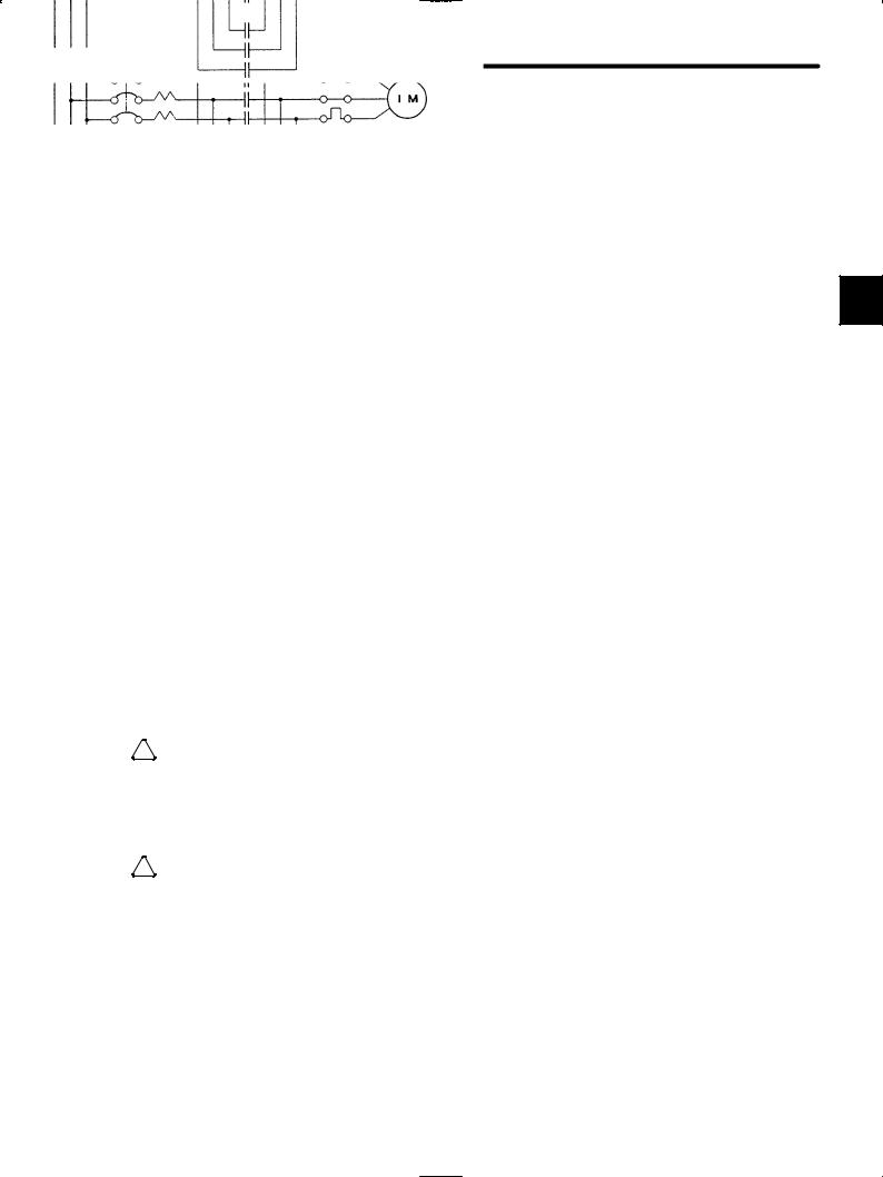
Always use an external interlock system as shown in the following example when reciprocal operations (e.g., forward and reverse directions) are being performed with a motor.
An interlock is generally programmed in the GL120/GL130 ladder program to ensure that forward and reverse signals are not simultaneously output. An external interlock circuit 1 must also be provided using the auxiliary contacts of electromagnetic contactors.
CPU Module Output Module
Ladder logic program
Output program with an interlock which prohibit simultaneous forward and reverse runs
Contact of overcurrent protection device.
Electric interlock using the auxiliary contacts of electromagnetic contactors
F (Forward run) |
Induction motor |
|
R (Reverse run)
! Caution Always make sure that power supply to the external power supply terminals (AC1, AC2) is OFF when operating the input voltage selector switch of Power Supply Module.
Operating the input voltage selector switch of Power Supply Module while power is being supplied to the external power supply terminals may damage the Module.
! Caution Set the Rack numbers according to the following rules.
If the Rack No. is not set according to the following rules, the PLC system will not run normally. In other words, it may result in failure of the CPU Module to run, communication errors, I/O process errors, etc.
•Set each Rack No. between 1 and 4 (rotary switch No: between 0 and 3).
•Always set the Rack No. where CPU Module or Remote I/O Receiver Module is installed to 1 (rotary switch: 0).
•Do not use the same Rack No. more than once at the same station.
—1-17 —

Introduction and Precautions
1.2.6Maintenance
1.2.6Maintenance
!WARNING Do not reverse the positive and negative terminals, charge, dismantle, heat, throw into fire or
short-circuit batteries.
These may cause explosion and/or ignition.
1 |
! Caution |
Do not disassemble or modify Modules and Mounting Bases. |
|
Doing so can cause fires, product failure, or malfunction.
! Caution Do not replace any of the built-in fuses.
Replacing built-in fuse by users may result in failure or malfunction of the Power Supply
Modules. Built-in fuse must be replaced by a Yaskawa service department.
Monitor the Life of Battery
•Monitor the life of the built-in battery in the CPU Module. If the “BAT ALM” indicator lights, replace the battery with a new one (replacement battery: BR-2/3A-1) within 2 weeks.
Delay in replacing the battery may result in the memory content loss of the ladder program and the motion program in the CPU Module and any Motion Modules.
•When the BAT Module’s “ALARM1” indicator lights, be sure to replace the battery with an ER6VC3N replacement battery within one week. Delay in replacing the battery may result in the memory content loss of the rotation data in the absolute encoder.
Regularly Overhaul Power Supply Modules
• Overhaul the Power Supply Module once every 5 years.
Deterioration of parts such as smoothing capacitors may result in malfunctioning of power supply sections. When a Power Supply Module is used in one of the following environment, overhaul more frequently.
•When used in places subject to high temperature or humidity, or subject to high variations in these.
•When variations in the power supply (voltage, frequency, wave-form distortion, etc.) or load are high.
•When subject to bad storage environments before use, including long-term storage or stoppage.
— 1-18 —

1.3 Using this Manual
1.3Using this Manual
This Manual is compiled for the following readers:
1) Those estimating purchase prices of GL120 or GL130 systems.
1
2) Those considering application of the GL120 or GL130.
3) Those designing control panels for the installation of the GL120 or GL130. 4) Those creating control panels to include the GL120 or GL130.
5) Those inspecting control panels on which GL120 or GL130 has been installed.
6) Those testing or adjusting control panels on which GL120 or GL130 has been installed. 7) Those maintaining control panels on which the GL120 or GL130 has been installed.
• Meaning of Basic Terms
In this manual, the following terms are defined as follows, unless otherwise specified:
•PLC = Programmable (Logic) Controller
•PP = Programming Panel
•GL120, GL130 = MEMOCON GL120 and/or MEMOCON GL130 Programmable Controller
— 1-19 —

Overview |
2 |
|
|
|
|
|
|
|
|
|
|
This chapter provides an outline of the MEMOCON GL120 and GL130, in- |
2 |
cluding system configuration examples, main modules, etc. |
2.1Overview of the MEMOCON GL120 and
GL130 . . . . . . . . . . . . . . . . . . . . . . . . . . . . . . . . . 2-2
— 2-1 —

Overview
2.1Overview of the MEMOCON GL120 and GL130
This section outlines the MEMOCON GL120 and GL130.
1) The MEMOCON GL120 (abbreviated GL120) and MEMOCON GL130 (abbreviated GL130) are programmable controllers (PLCs) developed to succeed the MEMOCONSC GL60 Series. The MEMOCON-SC GL60 Series has been well received and is very popular for key controllers in FA systems. The GL120 and GL130 are midto large-ca-
2 pacity programmable controllers. They provide greater compactness, higher quality, and higher performance while retaining the functions of the GL60 Series. The GL120 and GL130 have program memory capacity of 8K words, 16K words, 32K words, and 40K words, making the GL120 a mid-capacity controller and the GL130 a large-capacity controller.
2)The GL120 and GL130 can be used as high-speed machine controllers or as key controllers for various automatic devices, and can be applied to the following control:
D Sequence control |
D Motion control |
D Process control |
D Computational control |
3)The difference between the GL120 and GL130 lies in the CPU Module that is used. A PLC using the CPU20 CPU Module is a GL120, while a PLC using a CPU30 CPU Module is a GL130. All devices other than the CPU Module can be used in both PLCs.
Example 1
Example of system configuration for MEMOCON GL120
— 2-2 —

2.1 Overview of the MEMOCON GL120 and GL130
Example 2
Example of system configuration for MEMOCON GL130
2
PS10: |
Power Supply Module |
DI: |
Digital Input Module |
EXP: |
Expander Module |
|
(7 A) |
|
|
|
|
CPU20: |
CPU Module (16 KW) |
DO: |
Digital Output Module |
MB12: |
12-slot Mounting Base |
CPU30: |
CPU Module (32 KW) |
MC20: |
Four-axis Motion Module |
|
|
4)The following table shows the main Modules and other devices used in the GL120 and GL130. Any items listed as “Optional” in the Use column may be used as required according to the system control specifications of the GL120 or GL130.
Table 2.1 Main GL120 and GL130 Modules and other Products
Use |
Name |
|
Features |
|
|
|
|
Required |
Power Supply |
Supplies DC power to various Modules to operate them. |
|
|
Module |
|
|
Required |
CPU Module |
1) |
Stores the user program, solves the program based on the information |
|
|
|
from the input section, and outputs the results to the output section. |
|
|
|
There are 5 types of CPU Modules, namely the CPU10, CPU20, |
|
|
|
CPU21, CPU30, and CPU35. |
|
|
2) |
Equipped with 1 MEMOBUS port (slave, RS-232C). |
|
|
|
(CPU20, CPU21, CPU30, CPU35) |
|
|
3) |
Equipped with 1 MEMOBUS PLUS port |
|
|
|
(CPU20, CPU21, CPU30, CPU35) |
|
|
4) |
Execute the ROM operation. |
|
|
|
(CPU10, CPU21) |
— 2-3 —

Overview
|
|
Use |
Name |
|
Features |
|
|
|
|
|
|
|
|
Optional |
Communications |
1) |
Remote I/O Driver Module: |
|
|
|
Module |
|
Used as the master station of a Remote I/O system. |
|
|
|
|
2) |
Remote I/O Receiver Module: |
|
|
|
|
|
Used as the slave station of a Remote I/O system. |
|
|
|
|
3) |
2000-Series Remote I/O Driver Module: |
|
|
|
|
|
Used as the master station of a Remote I/O system for 2000 I/O. |
|
|
|
|
4) |
MEMOBUS Module (RS-232): |
|
|
|
|
|
Used to increase the number of RS-232C MEMOBUS ports. |
|
|
|
|
|
|
2 |
|
|
|
5) |
MEMOBUS Module (RS-422): |
|
|
|
|
||
|
|
|
|
|
Used to increase the number of RS-422 MEMOBUS ports. |
|
|
|
|
|
|
6)PC Link Module:
Used for high-speed communications between PLCs.
7)Uniwire Interface Module:
Used as the master station of a Uniwire system.
8)Uniwire H-system Interface Module:
Used as the master station of a Uniwire H-system.
9)Distributed I/O Driver Module:
Used as the master station of the VINUS I/O system.
10)M-NET Module:
Used for high-speed communications between PLCs.
11)YENET 1600-D Module:
Used for high-speed communications between PLCs.
12)Ethernet Interface Module:
Used for communications between PLCs.
13)Optical/Electrical Conversion Module:
Used for an Optical PC Link system or an Optical Remote I/O system.
Optional |
I/O Module |
1) |
Digital Input Module: |
|
|
|
Used to input digital signals. |
|
|
2) |
Analog Input Module: |
|
|
|
Used to input analog signals. |
|
|
3) |
Digital Output Module: |
|
|
|
Used to output digital signals. |
|
|
4) |
Analog Output Module: |
|
|
|
Used to output analog signals. |
— 2-4 —

2.1 Overview of the MEMOCON GL120 and GL130
Use |
Name |
|
Features |
|
|
|
|
|
|
|
|
Optional |
Special Purpose |
1) |
High-speed Counter Module (1 channel): |
|
|
|
Module |
|
Used to count high-speed pulses. |
|
|
|
|
2) |
Pulse Catch Module (16 channels): |
|
|
|
|
|
Used to read input signals that are ON for less than one scan time. |
|
|
|
|
3) |
Register I/O Module: |
|
|
|
|
|
Used to input/output the signal of the numerical value. |
|
|
|
|
|
|
|
|
Optional |
Motion Module |
1) |
Four-axis Motion Module: |
|
|
|
|
|
Used for 4-axis motion control. |
|
|
|
|
2) |
One-axis Motion Module: |
|
|
|
|
|
2 |
||
|
|
|
Used for 1-axis motion control. |
|
|
|
|
3) |
Two-axis Motion Module: |
|
|
|
|
|
|
||
|
|
|
Used for 2-axis motion control. |
|
|
|
|
|
|
|
|
Optional |
Expander Module |
Used to expand the number of racks. |
|
|
|
|
|
|
|
|
|
Required |
Mounting Base |
Used to install Modules. |
|
|
|
|
|
|
|
|
|
Optional |
Rack-to-rack I/O |
Used to connect between Expander Modules of adjacent racks. |
|
|
|
|
Cable |
|
|
|
|
Required (one |
Programming Panel |
1) |
A dedicated programming panel for MEMOCON PLCs. |
|
|
or the other) |
P120 |
|
|
|
|
|
|
2) |
Used for online or offline programming of the GL120 and GL130. |
|
|
|
MEMOSOFT |
A general-purpose personal computer software application for online or |
|
|
|
|
|
offline programming of the GL120 and GL130. (Software package) |
|
|
|
5)The difference of the GL120 and GL130 lies in the difference in specifications of the CPU Modules. The following table shows the specifications of the CPU10, CPU20, CPU21, CPU30, and CPU35 Modules. The main differences in specifications of the CPU Modules lies in their program memory capacities, the numbers of digital I/O points and scan times.
Table 2.2 CPU Module Summary Specifications
Item |
|
CPU10 |
CPU20 |
CPU21 |
CPU30 |
CPU35 |
|
|
(DDSCR- |
(DDSCR- |
(DDSCR- |
(DDSCR- |
(DDSCR- |
|
120CPU14200) |
120CPU34100) |
120CPU34110) |
130CPU54100) |
130CPU54110) |
|
|
|
|
|
|
|
|
Execution control |
Cyclic scan method |
|
|
|
||
method |
|
|
|
|
|
|
I/O connection |
1) |
Direct I/O |
|
|
|
|
method |
|
|
|
|
|
|
|
2) |
Remote I/O |
|
|
|
|
|
|
|
|
|
|
|
I/O control method |
1) |
Synchronous refresh |
|
|
|
|
|
2) |
Direct (direct I/O) |
|
|
|
|
|
|
|
||||
CPU |
General-purpose 16-bit microprocessor |
General-purpose 32-bit |
||||
|
|
|
|
|
microprocessor |
|
Programming |
Ladder diagram |
|
|
|
|
|
language |
|
|
|
|
|
|
— 2-5 —

Overview
|
|
Item |
|
CPU10 |
CPU20 |
|
CPU21 |
CPU30 |
CPU35 |
|
|
|
|
|
|
(DDSCR- |
(DDSCR- |
|
(DDSCR- |
(DDSCR- |
(DDSCR- |
|
|
|
|
120CPU14200) |
120CPU34100) |
|
120CPU34110) |
130CPU54100) |
130CPU54110) |
|
|
|
|
|
|
|
|
|
|
|
|
|
|
Types and number |
1) |
Basic instructions: 16 |
|
|
|
|||
|
|
of instructions |
|
|
|
|
|
|
|
|
|
|
CPU20: 166 |
2) |
Math operations: 25 |
|
|
|
|||
|
|
|
|
|
|
|
|
|
||
|
|
CPU30: 166 |
3) |
Data manipulation instructions: 48 |
|
|
|
|||
|
|
CPU35: 166 |
|
|
|
|||||
|
|
CPU21: 169 |
|
|
|
|
|
|
|
|
|
|
CPU10: 165 |
4) |
System status monitoring instruction: 1 |
|
|
||||
|
|
|
|
5) |
Sequence control instructions: 3 |
|
|
|
||
|
|
|
|
|
|
|
|
|
|
|
2 |
|
|
|
6) |
Program control instructions: 7 |
|
|
|
||
|
|
|
|
|
|
|
||||
|
|
|
|
7) |
I/O control instructions: 2 |
|
|
|
||
|
|
|
|
|
|
|
||||
|
|
|
|
8) |
Communications instructions: 9 (CPU10: 8) |
|
|
|||
|
|
|
|
9) |
Motion control instructions: 22 |
|
|
|
||
|
|
|
|
10) Expansion math instructions: 32 |
|
|
|
|||
|
|
|
|
11) Process control instruction: 1 |
|
|
|
|||
|
|
|
|
12) Expansion memory access instructions: 2 (CPU21) |
|
|
||||
|
|
|
|
|
|
|
|
|||
|
|
Scan time |
|
Ladder logic program: |
|
Ladder logic program: |
||||
|
|
|
|
Approx. 1 ms for 1K-word program |
|
Approx. 0.6 ms for 1K-word |
||||
|
|
|
|
|
|
|
|
|
program |
|
|
|
|
|
|
|
|
|
|
|
|
|
|
Program memory |
16K words |
|
|
|
32K words |
40K words |
||
|
|
capacity |
|
(1 word = 24 bits) |
|
|
|
(1 word = 24 |
(1 word = 24 |
|
|
|
|
|
|
|
|
|
|
bits) |
bits) |
|
|
|
|
|
|
|
|
|||
|
|
Maximum |
Digital |
1,024 points (1 point = 1 bit) *1 |
|
4,096 points (1 point = 1 bit) *1 |
||||
|
|
number |
I/O |
|
|
|
|
|
|
|
|
|
of input |
|
|
|
|
|
|
|
|
|
|
Register |
512 registers (1 register= 16 bits) * 2 |
|
|
|
||||
|
|
and |
|
|
|
|||||
|
|
I/O |
|
|
|
|
|
|
|
|
|
|
output |
|
|
|
|
|
|
|
|
|
|
|
|
|
|
|
|
|
|
|
|
|
Local |
1) |
Number of channels: 1 |
|
|
|
|||
|
|
points |
|
|
|
|||||
|
|
I/O |
|
|
|
|
|
|
|
|
|
|
|
|
|
|
|
|
|
|
|
|
|
|
|
2) |
Number of racks: 4 racks (including CPU rack) |
|
|
|||
|
|
|
|
3) |
Number of mountable I/O Modules: 54 |
|
|
|||
|
|
|
|
|
The total number of points, including remote I/O points, must not exceed the limits |
|||||
|
|
|
|
|
indicated at * 1 and * 2, above. |
|
|
|
||
|
|
|
|
|
|
|
|
|
||
|
|
|
Remote |
1) |
Number of channels: 2 |
|
|
|
||
|
|
|
I/O |
|
|
|
|
|
|
|
|
|
|
|
2) |
Number of stations per channel: 15 |
|
|
|||
|
|
|
|
3) |
Number of racks per station: 4 |
|
|
|
||
|
|
|
|
4) |
Number of I/O points per station: |
|
|
|
||
|
|
|
|
|
(Digital input points ÷ 8) + (register input points × 2) ± 512 bytes |
|
||||
|
|
|
|
|
(Digital output points ÷ 8) + (register output points × 2) ± 512 bytes |
|
||||
|
|
|
|
|
The total number of points, including local I/O points and remote I/O points of other |
|||||
|
|
|
|
|
remote stations, must not exceed the limits indicated at * 1 and * 2, above. |
|||||
— 2-6 —
Loading...