


G7
Table of contents
 Loading...
Electronic Lineshaft
with Alignment
G7 Drive Software
Technical Manual
Software Number: VSG13311X, Drive Models: CIMR-G7UXXXXXX-064, CIMR-G7UXXXXXX-065
Document Number: TM.G7SW.064, Date: 03/31/09, Rev: 09-03

This document is intended to provide proper installation and use of the Yaskawa drive with custom software. This
document is a supplement to the standard drive technical manual. It describes the effects on the drive parameters
and functions with the software installed. Read and understand this document and the standard drive technical
manuals before attempting to install, adjust, operate, inspect, or maintain the drive. Observe all cautions and
warnings in this document and the standard drive technical manuals. Custom software is written to add
functionality to a standard AC drive to enhance or enable use in a specific application. The software is loaded to
the flash ROM area of the control board, and replaces the standard drive software. Custom software can add new
functions, modify standard functions, or even inhibit standard functions. It can be used to modify display text or
parameter names. Custom software is usually loaded to the drive before delivery. The control board and drive
nameplate are assigned unique part numbers and the software is registered, archived, an d retrievable.
When seeking support for a drive with custom software, it is imperative to provide the unique part number shown
on the drive nameplate. The software has been flashed to the control board memory and the operation of
parameters, functions, and monitors are different than the standard drive software, as described herein.
1.0 Overview
The Electronic Lineshaft (ELS) function allows a drive to precisely follow a master encoder (PG) signal in
speed, direction, and phase. The follower can match its position (phase angle) to the master within several
quadrature encoder counts. The function is used in applications where the machinery being driven requires
two mechanically isolated, moving parts to maintain a constant position relationship. The gear ratio between
the master and the follower is infinitely adjustable. In addition, a gear ratio adjustment (“draw”) can be added
to the speed reference via parameter, analog input, multi-function input, MOP, or network communication.
The drive can also be run in a pure speed follower mode for applications that do not require matched position,
only velocity following.
Both the master and follower encoder signals are fed into the follower drive’s dual encoder (PG) option card.
The master encoder speed is multiplied by the programmed gear ratio to determine the speed reference. The
error between the master and follower position is determined. This is fed into a PI controller, which is in turn
added to the previously calculated speed reference. When the drive is configured as a speed follower, the
position regulator is disabled.
A signed-run mode is also available in ELS. When P1-01 = 5 (Electronic Line Shaft - Sign Run), ELS
functions identically to standard ELS (P1-01 = 4), with the following difference:
• When a reverse run command is given through the terminal S2 digital input, the follower will match the
velocity and phase of the master, but in the opposite direction. If the master runs in the forward direction,
the follower will run in reverse direction. If the master runs in the reverse direction, the follower will run in
the forward direction.
• When a forward run command is present through terminal S1, the follower will run in the same direction is
the master.
The Alignment function allows the follower drive to maintain a phase angle with respect to 2 alignment inputs
(can be sensors or encoder marker pulses). The phase angle, quantified as the Displacement in follower
encoder counts, can be adjusted during run either through keypad, digital multi-function inputs, or network
communication. The phase angle is maintained by monitoring alignment inputs (pulses) from both the master
alignment input and follower alignment input and then measuring the follower encoder counts received
between the two alignment pulses.
The Alignment function is enabled through the Align by Pulse multi-function digital input. When enabled, the
drive will monitor the Z (marker) channel inputs on any of the dual channel encoder option cards.
Please note that the alignment inputs need not come directly from encoder marker pulse channels. However,
special external circuitry may be required to support other input types, such as proximity sensors. Also, the
inputs do not have to be of the same type. Refer to Section 3.0 (Limitations) for application details.
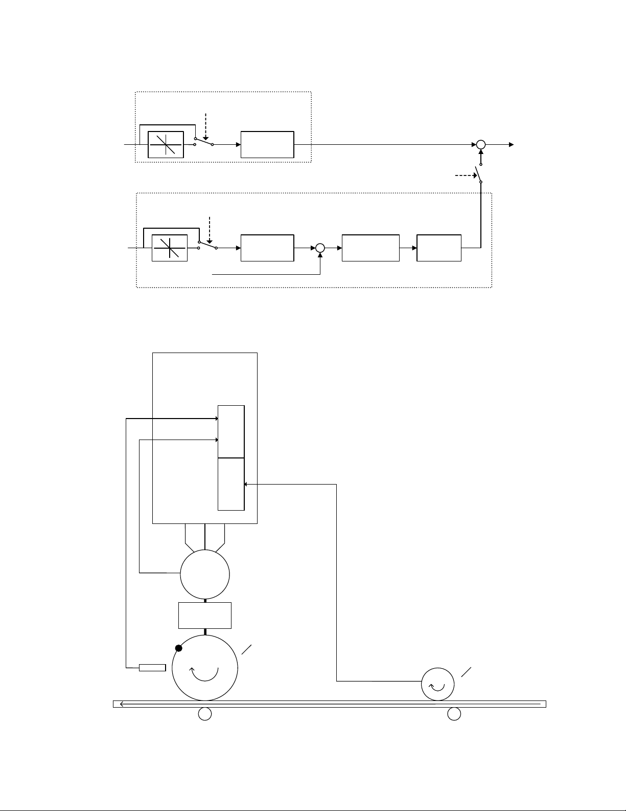
Figures 1 ~ 3 below give overview to the Electronic Lineshaft and Alignment functions.
Date: 03/31/09, Rev: 09-03 Page 2 of 30 TM.G7SW.064
A
A
Speed Calculation
ELS – Sign Mode Enabled
AND Reverse Run Command
Master Encoder
Master Encoder
Pulse Count
Proximity
Sensor for
Follower
Alignment
Speed
Input
+
+
Position Regulator
ELS – Sign Mode Enabled
AND Reverse Run Command
Follower Encoder
Pulse Count
Gear
Calculation
Gear
Calculation
ELS Mode Enabled OR
ELS – Sign Mode
Enabled
+
-
Position Error
Accumulator
PI
Controller
Figure 1: Simplified Block Diagram of the Electronic Lineshaft Function
G7 w/ ELS
PG-W2
Z
, B
Follower
Encoder
Feedback
Motor
Gear Box
Figure 2: Typical Connection Diagram of the Alignment Function
Ch 1
Ch 2
, B, Z
Follower
Machine
Section
Master
Encoder
Feedback
ith Marker
w
Pulse for
Master
Alignment
Input
Master
Machine
Section
Frequency
Reference
Date: 03/31/09, Rev: 09-03 Page 3 of 30 TM.G7SW.064

Input Channel
Monitor Output
Channel 1 Input
Channel 2 Input
Monitor Output
.
.
.
Channel 1 Input
Channel 2 Input
PG-X2
Pulse
Master Drive
PG-W2
Pulse
Follower Drive 1
PG-W2
Follower Drive n
G7
G7
.
.
.
G7
PG
M
PG
M
PG
M
Figure 3: Typical Connection Diagram for Basic Electronic Lineshaft
Date: 03/31/09, Rev: 09-03 Page 4 of 30 TM.G7SW.064

2.0 Changes from Standard Product
a. The Motor 2 Selection (H1-0X = 16) multi-function digital input function is deleted (only Motor 1 can be
used).
b. The kWh monitors (U1-29 and U1-30) are deleted.
c. Parameter E2-04 (Motor Poles) is available in all control modes (Advanced access level only for V/f and
Open Loop Vector).
d. The “User” access level and all of the associated “A2” parameters are deleted.
e. The follower drive uses acceleration and deceleration times of zero during standard Electronic Line Shaft
(P1-01 = 4, 5) and the Alignment function.
3.0 Limitations
a. For ELS modes (P1-01 = 4, 5), Flux Vector control mode must be used (A1-02 = 3).
b. For ELS modes (P1-01 = 4, 5), the gear ratio must be exactly expressed, including remainder, to prevent
phase drift (error). See section 5.0.
c. The Alignment function is available in Flux Vector control mode only (A1-02 = 3) and when P1-01 = 4 or 5
(ELS modes).
d. The Alignment function is only available in the forward direction.
e. The Alignment function is disabled when the motor speed is less than the DC Injection
Frequency (B2-01).
f. The alignment pulse from the master and the alignment pulse from the slave must be at a 1:1 ratio (the
software requires one follower alignment pulse for every one master alignment pulse).
g. The master alignment pulse must occur exactly once per master encoder revolution.
h. The proper encoder (PG) option card must be used based on the control mode and follower mode
selection. The table below shows the supported option cards for each configuration.
Encoder (PG) Option Card Selection
Control Mode P1-01 = 1, 2, 3 (Speed Follower) P1-01 = 4, 5 (ELS)
V/f w/ PG PG-W2, PG-Y2, PG-Z2
Open Loop Vector PG-B2, PG-T2, PG-X2, PG-W2, PG-Y2, PG-Z2
Flux Vector PG-W2, PG-Y2, PG-Z2
V/f PG-B2, PG-T2, PG-X2, PG-W2, PG-Y2, PG-Z2
PG-W2, PG-Y2, PG-Z2
Note: If the PG-W2 option is used, jumper HDR1 must be set to the “top” position
(using the 2 pins closest to the 4CN connector).
Date: 03/31/09, Rev: 09-03 Page 5 of 30 TM.G7SW.064
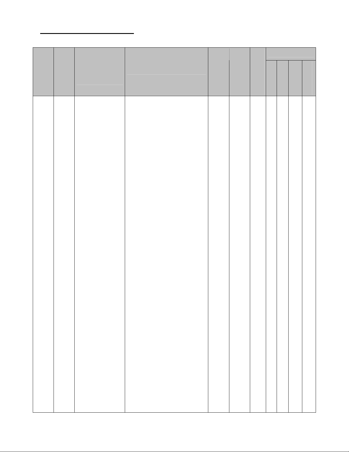
4.0 Related Parameters and Functions
4.1 Parameters
Change During
Parameter
Number
Address
Modbus
Parameter Name
Digital Operator
Range
Description
Default
Run
Display
Selects the follower mode.
0: Disabled
Follower mode is disabled
and the follower drive runs
from the normal frequency
reference (B1-01).
1: Speed – Both Dir
The follower drive follows
the master encoder speed
in both directions.
2: Speed – One Dir
The follower drive follows
the master encoder speed
in the direction of the run
command only.
3: Speed – Abs Val
The follower drive follows
the master encoder speed
but ignores the master
encoder direction (motion is
always in the direction of
P1-01 600H
Follower Mode
Selection
Follower Mode
the run command).
4: Elec Line Shaft
The follower drive follows
the master encoder speed
0 ~ 5 0 No Q Q Q Q
and position (both
directions). Terminals S1 or
S2 can be used to issue the
run command. There is no
directional effect.
5: ELS – Sign Run
The follower drive follows
the master encoder speed
and position (both
directions). When a forward
run command is present
(terminal S1), the drive
follows the master in the
same direction. When a
reverse run command is
present (terminal S2), the
drive follows in the opposite
direction of the master.
Note: Settings 4 and 5 are
available only in the Flux
Vector Mode (A1-02 = 3).
*1: Access Level (A1-01): Q = “Quick Start”, A = “Advanced”, F = “Factory”, – = Not Available.
Control Mode *1
Open Loop
Vector 1, 2
V/f w/ PG
V/f
Flux Vector
Date: 03/31/09, Rev: 09-03 Page 6 of 30 TM.G7SW.064

4.1 Parameters (continued)
Parameter
Number
Address
Modbus
Parameter Name
Digital Operator
Display
Description
Range
Default
Change During
Run
Control Mode *1
Open Loop
Vector 1, 2
V/f w/ PG
V/f
Flux Vector
P1-02 601H
P1-03 602H
Master Encoder
PPR
Master PG PPR
Ratio Numerator
(Upper 4 Digits)
Ratio Num High
Sets the pulses per revolution
(PPR) of the master encoder
(PG).
Sets the upper 4 digits of the
primary gear ratio numerator.
See section 5.1.
20 ~
60,000
Pulses
0 ~
9999
1024 No Q Q Q Q
1000 Yes Q Q Q Q
Ratio
P1-04 603H
Denominator
(Upper 4 Digits)
Sets the upper 4 digits of the
primary gear ratio
denominator. See section 5.1.
0 ~
9999
1000 Yes Q Q Q Q
Ratio Den High
P1-05 604H
Ratio Numerator
(Lower 4 Digits)
Ratio Num Low
Sets the lower 4 digits of the
primary gear ratio numerator.
See section 5.1.
0 ~
9999
0 Yes A A A A
Ratio
Sets the lower 4 digits of the
primary gear ratio
denominator. See section 5.1.
0 ~
9999
0 Yes A A A A
P1-06 605H
Denominator
(Lower 4 Digits)
Ratio Den Low
Sets the numerator of the
secondary gear ratio. Active
when a multi-function digital
input is set to 81 (Ratio 2
Select) and the input is closed.
Sets the denominator of the
secondary gear ratio. Active
when a multi-function digital
input is set to 81 (Ratio 2
Select) and the input is closed.
1 ~
65,535
1 ~
65,535
1 Yes A A A A
1 Yes A A A A
P1-07 606H
P1-08 607H
Ratio 2
Numerator
Ratio 2 Num
Ratio 2
Denominator
Ratio 2 Den
Selects when the position error
accumulator is enabled in the
follower drive.
P1-09 608H
Position Error
Accumulation
Selection
Pos Accum
Select
0: Only During Run
Position error is only
calculated when the
follower drive is running.
1: Always
Position error is calculated
0 ~ 1 0 No – – – A
whenever power is applied
to the follower drive.
Note: ELS modes only.
*1: Access Level (A1-01): Q = “Quick Start”, A = “Advanced”, F = “Factory”, – = Not Available.
Date: 03/31/09, Rev: 09-03 Page 7 of 30 TM.G7SW.064

4.1 Parameters (continued)
Change During
Parameter
Number
Address
Modbus
Parameter Name
Digital Operator
Range
Description
Default
Run
Display
Selects the units used for the
follower drive Position Error
Monitor (U1-96).
0: Encoder Counts
Position error is displayed in
quadrature follower encoder
counts (cts).
1: Motor Revs
P1-10 609H
Position Units
Selection
Position Units
Position error is displayed in
follower motor revolutions
(0.001rev).
2: Motor Degrees
0 ~ 3 0 Yes – – – A
Position error is displayed in
follower motor degrees
(0.1°).
3: Motor Radians
Position error is displayed in
follower motor radians
(0.001rad).
Note: ELS modes only.
Sets the digital gear ratio
adjustment of the follower
drive. The gear ratio
adjustment is also influenced
by the analog, MOP and
communication gear ratio
-99.99
~
+99.99
%
0.00 Yes A A A A
P2-01 60AH
Digital Ratio
Adjustment
Digital RatioAdj
adjustments.
Sets the time for the MOP ratio
P2-02 60BH
MOP Adjust Time
MOP Adjust
Time
adjustment to change by
100.00% when the MOP
Adjust Increase or MOP Adjust
Decrease multi-function input
0.0 ~
6000.0
sec
50.0 Yes A A A A
is closed.
P2-03 60CH
Gear Ratio
Adjustment Ramp
Time
Ratio Adj Ramp
Sets the time for the composite
gear ratio adjustment of the
follower drive to change by
100.00%.
0.0 ~
6000.0
sec
10.0 Yes A A A A
*1: Access Level (A1-01): Q = “Quick Start”, A = “Advanced”, F = “Factory”, – = Not Available.
Control Mode *1
Open Loop
Vector 1, 2
V/f w/ PG
V/f
Flux Vector
Date: 03/31/09, Rev: 09-03 Page 8 of 30 TM.G7SW.064

4.1 Parameters (continued)
Change During
Parameter
Number
Address
Modbus
Parameter Name
Digital Operator
Range
Description
Default
Run
Display
Selects the advance/retard
functionality of the follower
drive.
0: Continuous
The follower will advance or
retard continuously while
the Advance Follower or
Retard Follower multifunction input is closed. P205 sets amount of
advance/retard encoder
counts per second.
1: Step
0 ~ 1 0 No – – – A
P2-04 60DH
Advance/Retard
Mode Selection
Adv/Ret Mode
Sel
The follower will advance or
retard by the amount set in
parameter P2-05 each time
the Advance Follower or
Retard Follower multifunction input is closed.
Note: ELS modes only.
Sets the number of quadrature
follower encoder counts the
follower will advance/retard per
second when P2-04 = 0. Sets
the step amount of the
advance/retard function when
P2-04 = 1.
0 ~
65,535
Counts
2048 Yes – – – A
P2-05 60EH
Advance/Retard
Amount
Adv/Ret Amount
Note: ELS modes only.
Sets the amount of position
error in quadrature follower
encoder counts that will
P2-06 60FH
Follower
Deviation Level
Follower Dev Lvl
activate the follower deviation
detection. Also sets the
scaling for the Position Error
analog output selection (H3-
0 ~
65,535
Counts
4096 No – – – A
05, H3-09 = 94).
Note: ELS modes only.
*1: Access Level (A1-01): Q = “Quick Start”, A = “Advanced”, F = “Factory”, – = Not Available.
Control Mode *1
Open Loop
Vector 1, 2
V/f w/ PG
V/f
Flux Vector
Date: 03/31/09, Rev: 09-03 Page 9 of 30 TM.G7SW.064
Loading...