


 Loading...
F7 Drive
User Manual
|
|
|
|
|
|
|
|
|
|
|
|
|
|
|
|
|
|
|
|
|
|
|
|
|
|
Model: CIMR-F7U |
Document Number: TM.F7.01 |
|
|
||
|
|
|
|
|
|
|
|
|
|
|
|
|
|
|
|

Warnings and Cautions
This Section provides warnings and cautions pertinent to this product, that if not heeded, may result in personal injury, fatality, or equipment damage. Yaskawa is not responsible for consequences of ignoring these instructions.

 WARNING
YASKAWA manufactures component parts that can be used in a wide variety of industrial applications. The selection and application of YASKAWA products remain the responsibility of the equipment designer or end user. YASKAWA accepts no responsibility for the way its products are incorporated into the final system design. Under no circumstances should any YASKAWA product be incorporated into any product or design as the exclusive or sole safety control. Without exception, all controls should be designed to detect faults dynamically and fail safely under all circumstances. All products designed to incorporate a component part manufactured by YASKAWA must be supplied to the end user with appropriate warnings and instructions as to that part’s safe use and operation. Any warnings provided by YASKAWA must be promptly provided to the end user. YASKAWA offers an express warranty only as to the quality of its products in conforming to standards and specifications published in the YASKAWA manual. NO OTHER WARRANTY, EXPRESS OR IMPLIED, IS OFFERED. YASKAWA assumes no liability for any personal injury, property damage, losses, or claims arising from misapplication of its products.

 WARNING
•Read and understand this manual before installing, operating, or servicing this Drive. All warnings, cautions, and instructions must be followed. All activity must be performed by qualified personnel. The Drive must be installed according to this manual and local codes.
•Do not connect or disconnect wiring while the power is on. Do not remove covers or touch circuit boards while the power is on. Do not remove or insert the digital operator while power is on.
•Before servicing, disconnect all power to the equipment. The internal capacitor remains charged even after the power supply is turned off. The charge indicator LED will extinguish when the DC bus voltage is below 50Vdc. To prevent electric shock, wait at least five minutes after all indicators are OFF and measure DC bus voltage level to confirm safe level.
•Do not perform a withstand voltage test on any part of the unit. This equipment uses sensitive devices and may be damaged by high voltage.

 WARNING
•The Drive is suitable for circuits capable of delivering not more than 100,000 RMS symmetrical Amperes, 240Vac maximum (200V Class) and 480Vac maximum (400V Class). Install adequate branch circuit short circuit protection per applicable codes. Failure to do so may result in equipment damage and/or personal injury. Refer to Appendix E for further details.
•Do not connect unapproved LC or RC interference suppression filters, capacitors, or overvoltage protection devices to the output of the Drive. These devices may generate peak currents that exceed Drive specifications.
i
•To avoid unnecessary fault displays caused by contactors or output switches placed between Drive and motor, auxiliary contacts must be properly integrated into the control logic circuit.
•YASKAWA is not responsible for any modification of the product made by the user; doing so will void the warranty. This product must not be modified.
•Verify that the rated voltage of the Drive matches the voltage of the incoming power supply before applying power.
•To meet CE directives, proper line filters and proper installation are required.
•Some drawings in this manual may be shown with protective covers or shields removed, to describe details. These must be replaced before operation.
•Observe electrostatic discharge procedures when handling circuit boards to prevent ESD damage.
•The equipment may start unexpectedly upon application of power. Clear all personnel from the Drive, motor, and machine area before applying power. Secure covers, couplings, shaft keys, and machine loads before energizing the Drive.
•Please do not connect or operate any equipment with visible damage or missing parts. The operating company is responsible for any injuries or equipment damage resulting from failure to heed the warnings in this manual.
Intended Use
Drives are intended for installation in electrical systems or machinery.
The Drives are designed and manufactured in accordance with applicable UL and cUL standards, and CE directives.
For use in the European Union, the installation in machinery and systems must conform to the following product standards of the Low Voltage Directive:
EN 50178: 1997-10, Electronic Equipment for Use in Power Installations
EN 60201-1: 1997-12 Machine Safety and Equipping with Electrical Devices
Part 1: General Requirements (IEC 60204-1:1997)
EN 61010: 1997-11 Safety Requirements for Information Technology Equipment (IEC 950:1991 + A1:1992 + A2:1993 + A3:1995 + A4:1996, modified)
The F7 series Drives comply with the provisions of the Low Voltage Directive 73/23/EEC as amended by 93/68/EEC. These Drives conform to the following standard: EN 50178: 1997-10.
Your supplier or Yaskawa representative must be contacted when using leakage current circuit breaker in conjunction with frequency inverters.
In certain systems it may be necessary to use additional monitoring and safety devices in compliance with the relevant safety and accident prevention regulations. The frequency inverter hardware must not be modified.
ii

Introduction
This section describes the applicability of the manual.
This manual is applicable to F7 Drives defined by model numbers of CIMR-F7U |
. This manual reflects the Software |
Version 3020. |
|
The F7 Drive is a Pulse Width Modulated Drive for AC 3-Phase induction motors. This type of Drive is also known as an Adjustable Frequency Drive, Variable Frequency Drive, AC Drive, AFD, ASD, VFD, VSD, and Inverter. In this manual, the F7 Drive will be referred to as the “Drive”.
The LCD keypad/operator is equipped with local/remote functions, copy feature, 7 language choices, and 5 lines of display with 16 characters per line. User parameter settings can be recovered at any time via “user initialization” when enabled. Optional Drive Wizard software allows upload/download, as well as graphing and monitoring of Drive parameters from a PC for ease of Drive management.
This manual may describe trademarked equipment, which is the property of other companies, who are the registered owners.
Other Documents and Manuals are available to support special use or installation of this product. These documents may be provided with the product or upon request. Contact Yaskawa Electric America, Inc. as required. Documents may include the following:
TM.F7.01…Manual included on CD ROM with product
TM.F7.02…Programming Manual included on CD ROM with product
DriveWizard...Software and Manual…Included on CD ROM with product
Option Instructions… Included on CD ROM with product
This manual is subject to change as product improvements occur. The latest version of the manual can be obtained from the Yaskawa website: www.yaskawa.com. The date shown on the rear cover is changed when revisions are made. The latest version of Drive software is also shown.
The Drive’s capacity is categorized based on two types of load characteristics: Heavy Duty and Normal Duty. See Table i.1 below for the differences between Heavy Duty and Normal Duty.
Table i.1 Drive Duty Selection
Parameter |
Rated Output |
Overload |
Current Limit |
Carrier |
Maximum Output |
|
C6-01 |
Current |
Capacity |
Frequency |
Frequency |
||
|
||||||
0: Heavy Duty |
Standard rating |
150% for 1 min. |
150% |
Low |
300Hz |
|
(default) |
(varies by model*) |
(2kHz**) |
||||
|
|
|
||||
|
|
|
|
|
|
|
2: Normal Duty |
Extended rating |
Approx. 110% for 1 min. |
120% |
High |
400Hz |
|
(varies by model*) |
(varies by model*) |
(varies by model*) |
||||
|
|
|
||||
|
|
|
|
|
|
* See Drive Specifications
** Software version VSF103021 and higher allows the carrier frequency to be increased while in HD (C6-01=0). The continuous current and overload are automatically reduced to the levels indicated in Table 5.1.
This manual references the various Drive capacities according to its model number CIMR-F7U . See Drive Output Specifications Table i.2 and Table i.3 on the following pages for rated capacities and Drive specifications.
iii

Drive Output Specifications
The standard Drive specifications are listed in the following tables.
208-240Vac
|
|
|
|
|
|
Table i.2 208-240Vac Drive Specifications |
|
|
|
|
|
|
|
|||||||
|
|
|
|
|
|
|
208-240Vac |
|
|
|
|
|
|
|
208-230Vac |
|
|
|||
Model Number CIMR-F7U |
20P4 |
20P7 |
21P5 |
22P2 |
23P7 |
25P5 |
27P5 |
2011 |
2015 |
2018 |
2022 |
2030 |
2037 |
2045 |
2055 |
2075 |
2090 |
2110*5 |
||
|
|
Rated output |
1.2 |
1.6 |
2.7 |
3.7 |
5.7 |
8.8 |
12.0 |
17.0 |
22.0 |
27.0 |
32.0 |
44.0 |
55.0 |
69.0 |
82.0 |
110.0 |
130.0 |
140.0 |
|
|
capacity (kVA) |
||||||||||||||||||
|
|
|
|
|
|
|
|
|
|
|
|
|
|
|
|
|
|
|
|
|
|
|
|
|
|
|
|
|
|
|
|
|
|
|
|
|
|
|
|
|
|
|
|
Horsepower*2 |
0.5/0.75 |
1 |
2 |
3 |
5 |
7.5 |
10 |
15 |
20 |
25 |
30 |
40 |
50 |
60 |
75 |
100 |
125 |
150 |
|
|
Rated output |
3.2 |
4.2 |
7.0 |
9.6 |
15.2 |
23.0 |
31.0 |
45.0 |
58.0 |
71 |
85.0 |
115.0 |
145.0 |
180.0 |
215 |
283.0 |
346.0 |
360.0 |
|
|
current (A) |
||||||||||||||||||
|
*1 |
|
|
|
|
|
|
|
|
|
|
|
|
|
|
|
|
|
|
|
|
Duty |
Overload capacity*3 |
|
|
|
|
|
|
|
|
150 |
|
|
|
|
|
|
|
|
138*3 |
|
(% of rated output |
|
|
|
|
|
|
|
|
|
|
|
|
|
|
|
|
|||
|
Heavy |
current for 60 sec.) |
|
|
|
|
|
|
|
|
|
|
|
|
|
|
|
|
|
|
|
|
|
|
|
|
|
|
|
|
|
|
|
|
|
|
|
|
|
|
|
|
|
|
|
|
|
|
|
|
|
|
|
|
|
|
|
|
|
|
|
|
|
|
Current limit (% of |
|
|
|
|
|
|
|
|
150 |
|
|
|
|
|
|
|
|
138*3 |
|
|
rated output current) |
|
|
|
|
|
|
|
|
|
|
|
|
|
|
|
|
||
|
|
|
|
|
|
|
|
|
|
|
|
|
|
|
|
|
|
|
|
|
|
|
Carrier frequency*4 |
|
|
|
|
|
|
|
|
2kHz |
|
|
|
|
|
|
|
|
|
|
|
Maximum output |
|
|
|
|
|
|
|
|
300.0Hz |
|
|
|
|
|
|
|
|
|
|
|
frequency |
|
|
|
|
|
|
|
|
|
|
|
|
|
|
|
|
||
ratings |
|
1.4 |
1.8 |
3.0 |
4.1 |
6.4 |
8.8 |
12.0 |
18.0 |
23.0 |
29.0 |
34.0 |
44.0 |
62.0 |
73.0 |
82.0 |
120.0 |
140.0 |
160.0 |
|
|
|
Rated output |
|
|
|
|
|
|
|
|
|
|
|
|
|
|
|
|
|
|
Output |
|
capacity (kVA) |
|
|
|
|
|
|
|
|
|
|
|
|
|
|
|
|
|
|
|
|
|
|
|
|
|
|
|
|
|
|
|
|
|
|
|
|
|
|
|
|
Horsepower*2 |
0.5/0.75 |
1 |
2 |
3 |
5 |
7.5 |
10 |
15 |
20 |
25 |
30 |
40 |
50/60 |
75 |
75 |
100/125 |
150 |
150 |
|
|
|
|||||||||||||||||||
|
|
Rated output |
3.6 |
4.6 |
7.8 |
10.8 |
16.8 |
23.0 |
31.0 |
46.2 |
59.4 |
74.8 |
88.0 |
115.0 |
162.0 |
192.0 |
215 |
312.0 |
360.0 |
415.0 |
|
|
current (A) |
||||||||||||||||||
|
*1 |
|
|
|
|
|
|
|
|
|
|
|
|
|
|
|
|
|
|
|
|
Overload capacity*3 |
|
|
|
|
|
|
|
|
|
|
|
|
|
|
|
|
|
|
|
|
Duty |
107 |
107 |
108 |
107 |
107 |
120 |
120 |
117 |
117 |
114 |
116 |
120 |
107 |
113 |
120 |
109 |
115 |
120 |
|
|
(% of rated output |
|||||||||||||||||||
|
Normal |
Current limit (% of |
|
|
|
|
|
|
|
|
|
|
|
|
|
|
|
|
|
|
|
|
current for 60 sec.) |
|
|
|
|
|
|
|
|
|
|
|
|
|
|
|
|
|
|
|
|
rated output current) |
|
|
|
|
|
|
|
|
120 |
|
|
|
|
|
|
|
|
|
|
|
|
|
|
|
|
|
|
|
|
|
|
|
|
|
|
|
|
|
|
|
|
Carrier frequency |
10 |
10 |
10 |
8 |
10 |
15 |
15 |
8 |
10 |
10 |
10 |
10 |
5 |
5 |
8 |
2 |
2 |
2 |
|
|
(kHz)*5 |
||||||||||||||||||
|
|
|
|
|
|
|
|
|
|
|
|
|
|
|
|
|
|
|
|
|
|
|
Maximum output |
|
|
|
|
|
|
|
|
400.0Hz |
|
|
|
|
|
|
|
|
|
|
|
frequency |
|
|
|
|
|
|
|
|
|
|
|
|
|
|
|
|
||
|
|
|
|
|
|
|
|
|
|
|
|
|
|
|
|
|
|
|
|
|
|
Maximum output voltage |
|
|
|
|
|
|
3-phase; 200, 208, 220, 230, or 240Vac |
|
|
|
|
|
|
||||||
|
|
|
|
|
|
|
(Proportional to input voltage) |
|
|
|
|
|
|
|||||||
|
|
|
|
|
|
|
|
|
|
|
|
|
|
|
||||||
*1 |
The difference between Heavy |
Duty ratings and the Normal Duty ratings for the Drive are the rated input and output current, overload capacity, carrier frequency, current limit, and |
||||||||||||||||||
maximum output frequency. Parameter C6-01 must be set to value of “0” for Heavy Duty ratings and “2” for Normal Duty ratings. Factory default is Heavy Duty (C6-01=0). |
||||||||||||||||||||
*2 Horsepower ratings are based on 230V or 460V NEC Table 430.150. The maximum applicable motor output is given for a standard 4-pole motor. When selecting the actual motor and Drive, be sure that the Drive's rated output current is appropriate for the motor's rated current.
*3 Model 2110 has an overload rating of 138% of rated output current for 60 seconds and a current limit rating of 138%. Models 4220 and 4300 have an overload rating of 150% of rated output current for 45 seconds and a current limit rating of 150%.
*4 When setting the carrier frequency above the factory default, the Drive must be derated.
*5 Heavy Duty ratings for models 2110, 4220 and 4300 are effective in software version VSF103021 and higher.
iv

480Vac
|
|
|
|
|
Table i.3 480Vac Drive Specifications |
|
|
|
|
|
|||||
Model Number CIMR-F7U |
40P4 |
40P7 |
41P5 |
42P2 |
43P7 |
44P0 |
|
45P5 |
47P5 |
4011 |
4015 |
4018 |
4022 |
||
|
|
Rated output |
1.4 |
1.6 |
2.8 |
4.0 |
5.8 |
6.6 |
|
9.5 |
13.0 |
18.0 |
24.0 |
30.0 |
34.0 |
|
|
capacity (kVA) |
|
||||||||||||
|
|
|
|
|
|
|
|
|
|
|
|
|
|
|
|
|
|
|
|
|
|
|
|
|
|
|
|
|
|
|
|
|
|
Horsepower*2 |
0.5/0.75 |
1 |
1.5/2 |
3 |
5 |
- |
|
7.5 |
10 |
15 |
20 |
25 |
30 |
|
*1 |
Rated output current (A) |
1.8 |
2.1 |
3.7 |
5.3 |
7.6 |
8.7 |
|
12.5 |
17.0 |
24.0 |
31.0 |
39.0 |
45.0 |
|
Overload capacity*3 |
|
|
|
|
|
|
|
|
|
|
|
|
|
|
|
Duty |
|
|
|
|
|
|
150 |
|
|
|
|
|
||
|
(% of rated output |
|
|
|
|
|
|
|
|
|
|
|
|||
|
Heavy |
current for 60 sec.) |
|
|
|
|
|
|
|
|
|
|
|
|
|
|
|
|
|
|
|
|
|
|
|
|
|
|
|
|
|
|
|
Current limit (% of rated |
|
|
|
|
|
|
150 |
|
|
|
|
|
|
|
|
output current) |
|
|
|
|
|
|
|
|
|
|
|
||
|
|
|
|
|
|
|
|
|
|
|
|
|
|
|
|
|
|
Carrier frequency*4 |
|
|
|
|
|
2kHz |
|
|
|
|
|
||
ngs |
|
Maximum output |
|
|
|
|
|
300.0Hz |
|
|
|
|
|
||
|
frequency |
|
|
|
|
|
|
|
|
|
|
||||
rati |
|
|
|
|
|
|
|
|
|
|
|
|
|
|
|
Output |
|
Rated output capacity (kVA) |
1.4 |
1.6 |
2.8 |
4.0 |
5.8 |
6.6 |
|
9.5 |
13.0 |
21.0 |
26.0 |
30.0 |
38.0 |
|
Horsepower*2 |
0.5/0.75 |
1 |
1.5/2 |
3 |
5 |
- |
|
7.5 |
10 |
15/20 |
25 |
30 |
30 |
|
|
|
Rated output current (A) |
1.8 |
2.1 |
3.7 |
5.3 |
7.6 |
8.7 |
|
12.5 |
17.0 |
27.0 |
34.0 |
40.0 |
50.4 |
|
|
|
|
|
|
|
|
|
|
|
|
|
|
|
|
|
*1 |
Overload capacity*3 |
|
|
|
|
|
|
|
|
|
|
|
|
|
|
Duty |
(% of rated output |
120 |
120 |
120 |
120 |
120 |
120 |
|
120 |
120 |
107 |
109 |
117 |
107 |
|
|
|
|||||||||||||
|
Normal |
current for 60 sec.) |
|
|
|
|
|
|
|
|
|
|
|
|
|
|
|
|
|
|
|
|
|
|
|
|
|
|
|
|
|
|
Current limit (% of rated |
|
|
|
|
|
|
120 |
|
|
|
|
|
||
|
|
output current) |
|
|
|
|
|
|
|
|
|
|
|
|
|
|
|
Carrier frequency (kHz)*5 |
15 |
15 |
15 |
15 |
15 |
15 |
|
15 |
15 |
8 |
10 |
10 |
10 |
|
|
Maximum output |
|
|
|
|
|
400.0Hz |
|
|
|
|
|
||
|
|
frequency |
|
|
|
|
|
|
|
|
|
|
|||
|
|
|
|
|
|
|
|
|
|
|
|
|
|
|
|
|
Maximum output voltage |
|
|
3-phase; 380, 400, 415, 440, 460, or 480Vac (Proportional to input voltage) |
|
|
|||||||||
Model Number CIMR-F7U |
4030 |
4037 |
4045 |
4055 |
4075 |
|
4090 |
|
4110 |
4132 |
4160 |
4185 |
4220 |
4300 |
|||
|
|
Rated output capacity |
46.0 |
57.0 |
69.0 |
85.0 |
110.0 |
|
140.0 |
|
160.0 |
200.0 |
230.0 |
280.0 |
315.0 |
450.0 |
|
|
|
(kVA) |
|
|
|
||||||||||||
|
|
|
|
|
|
|
|
|
|
|
|
|
|
|
|
|
|
|
|
Horsepower*2 |
40 |
50 |
60 |
75 |
100 |
|
125/150 |
|
- |
200 |
250 |
300 |
350 |
500 |
|
|
|
Rated output current (A) |
60.0 |
75.0 |
91.0 |
112.0 |
150.0 |
|
180.0 |
|
216.0 |
260.0 |
304.0 |
370.0 |
414.0 |
590.0 |
|
|
*1 |
|
|
|
|
|
|
|
|
|
|
|
|
|
|
|
|
|
Overload capacity*3 |
|
|
|
|
|
|
|
|
|
|
|
|
|
|
||
|
Duty |
(% of rated output |
|
|
|
|
|
150 |
|
|
|
|
|
150*3 |
150*3 |
||
|
Heavy |
current for 60 sec.) |
|
|
|
|
|
|
|
|
|
|
|
|
|
|
|
|
|
|
|
|
|
|
|
|
|
|
|
|
|
|
|
||
|
Current limit (% of rated |
|
|
|
|
|
150 |
|
|
|
|
|
150*3 |
150*3 |
|||
|
|
output current) |
|
|
|
|
|
|
|
|
|
|
|||||
|
|
|
|
|
|
|
|
|
|
|
|
|
|
|
|
||
|
|
Carrier frequency*4 |
|
|
|
|
|
|
|
|
2kHz |
|
|
|
|
|
|
ings |
|
Maximum output |
|
|
|
|
|
|
|
300.0Hz |
|
|
|
|
|
||
|
frequency |
|
|
|
|
|
|
|
|
|
|
|
|
|
|||
rat |
|
|
|
|
|
|
|
|
|
|
|
|
|
|
|
|
|
utput |
|
Rated output capacity(kVA) |
51.0 |
59.0 |
73.0 |
95.0 |
120.0 |
|
140.0 |
|
180.0 |
200.0 |
230.0 |
315.0 |
390.0 |
510.0 |
|
|
Horsepower |
*2 |
40/50 |
60 |
75 |
100 |
125 |
|
150 |
|
200 |
- |
250 |
300/350 |
400/450 |
500+ |
|
O |
|
|
|
|
|||||||||||||
|
|
Rated output current (A) |
67.2 |
77.0 |
96.0 |
125.0 |
156.0 |
|
180.0 |
|
240.0 |
260.0 |
304.0 |
414.0 |
515.0 |
675.0 |
|
|
|
|
|
|
|
|
|
|
|
|
|
|
|
|
|
|
|
|
*1 |
Overload capacity*3 |
107 |
117 |
114 |
108 |
115 |
|
120 |
|
108 |
120 |
120 |
107 |
118 |
120 |
|
|
Duty |
(% of rated output |
|
|
|||||||||||||
|
current for 60 sec.) |
|
|
|
|
|
|
|
|
|
|
|
|
|
|
||
|
Normal |
|
|
|
|
|
|
|
|
|
|
|
|
|
|
||
|
Current limit (% of rated |
|
|
|
|
|
|
|
120 |
|
|
|
|
|
|||
|
output current) |
|
|
|
|
|
|
|
|
|
|
|
|
||||
|
|
|
|
|
|
|
|
|
|
|
|
|
|
|
|
||
|
|
Carrier frequency (kHz)*5 |
8 |
8 |
8 |
5 |
5 |
|
8 |
|
5 |
5 |
5 |
2 |
2 |
2 |
|
|
|
Maximum output |
|
|
|
|
|
|
|
400.0Hz |
|
|
|
|
|
||
|
|
frequency |
|
|
|
|
|
|
|
|
|
|
|
|
|
||
|
|
|
|
|
|
|
|
|
|
|
|
|
|
|
|
|
|
|
Maximum output voltage |
|
|
3-phase, 380, 400, 415, 440, 460 or 480Vac (Proportional to input voltage) |
|
|
|||||||||||
*1 The difference between Heavy Duty ratings and the Normal Duty ratings for the Drive are the rated input and output current, overload capacity, carrier frequency, current limit, and maximum output frequency. Parameter C6-01 must be set to value of “0” for Heavy Duty ratings and “2” for Normal Duty ratings. Factory default is Heavy Duty (C6-01=0).
*2 Horsepower ratings are based on 230V or 460V NEC Table 430.150. The maximum applicable motor output is given for a standard 4-pole motor. When selecting the actual motor and Drive, be sure that the Drive's rated output current is appropriate for the motor's rated current.
*3 Model 2110 has an overload rating of 138% of rated output current for 60 seconds and a current limit rating of 138%. Models 4220 and 4300 have an overload rating of 150% of rated output current for 45 seconds and a current limit rating of 150%.
*4 When setting the carrier frequency above the factory default, the Drive must be derated.
*5 Heavy Duty ratings for models 2110, 4220 and 4300 are effective in software version VSF103021 and higher.
v
Notes:
vi

Table of Contents
Warnings and Cautions |
..................................................................................... i |
Introduction ..................................................................................................... |
iii |
Table of Contents........................................................................................... |
vii |
Chapter 1 - Physical Installation ............................................................................... |
1-1 |
F7 Model Number, Enclosure, Heat Loss, and Weight................................. |
1-2 |
Confirmations upon Delivery......................................................................... |
1-3 |
Component Names ....................................................................................... |
1-5 |
Exterior and Mounting Dimensions ............................................................... |
1-7 |
Checking and Controlling the Installation Site ............................................ |
1-11 |
Installation Orientation and Clearances ...................................................... |
1-12 |
Removing and Attaching the Terminal Cover ............................................. |
1-13 |
Removing/Attaching the Digital Operator and Front Cover......................... |
1-14 |
Chapter 2 - Electrical Installation.............................................................................. |
2-1 |
Terminal Block Configuration........................................................................ |
2-2 |
Wiring Main Circuit Terminals ....................................................................... |
2-3 |
Control Wiring ............................................................................................. |
2-20 |
Electromagnetic Compatibility (EMC) ......................................................... |
2-26 |
Installing and Wiring Option Boards............................................................ |
2-30 |
Chapter 3 - Digital Operator ...................................................................................... |
3-1 |
Digital Operator Display ................................................................................ |
3-2 |
Digital Operator Keys.................................................................................... |
3-3 |
Drive Mode Indicators ................................................................................... |
3-4 |
Drive Main Menus ......................................................................................... |
3-6 |
Quick Setting Menu (-QUICK-) ................................................................... |
3-11 |
Programming Menu (-ADV-) ....................................................................... |
3-12 |
Example of Changing a Parameter............................................................. |
3-15 |
Table of Contents vii
Chapter 4 - Start-Up ................................................................................................... |
4-1 |
Drive Start-Up Preparation ........................................................................... |
4-2 |
Drive Start-Up Procedures ........................................................................... |
4-5 |
Chapter 5 - Basic Programming ............................................................................... |
5-1 |
Description of Parameter Tables .................................................................. |
5-2 |
Control Method ............................................................................................. |
5-2 |
Speed Command Source ............................................................................. |
5-3 |
Run Command Source ................................................................................. |
5-4 |
Stopping Method .......................................................................................... |
5-5 |
Accel/Decel Time.......................................................................................... |
5-8 |
Carrier Frequency......................................................................................... |
5-9 |
Preset Reference........................................................................................ |
5-11 |
Input Voltage Setting .................................................................................. |
5-12 |
V/F Pattern ................................................................................................. |
5-12 |
Motor Setup ................................................................................................ |
5-20 |
PG Option................................................................................................... |
5-20 |
Analog Output Gain .................................................................................... |
5-21 |
Motor Overload Fault.................................................................................. |
5-22 |
Stall Prevention .......................................................................................... |
5-23 |
Chapter 6 - Diagnostics & Troubleshooting............................................................ |
6-1 |
Fault Detection ............................................................................................. |
6-2 |
Alarm Detection .......................................................................................... |
6-10 |
Operator Programming Errors (OPE) ......................................................... |
6-15 |
Auto-Tuning Faults ..................................................................................... |
6-17 |
Digital Operator COPY Function Faults...................................................... |
6-19 |
Troubleshooting.......................................................................................... |
6-20 |
Main Circuit Test Procedure ....................................................................... |
6-28 |
Drive Date Stamp Information ................................................................... |
6-31 |
Table of Contents viii
Chapter 7 - Maintenance............................................................................................ |
7-1 |
Periodic Inspection........................................................................................ |
7-2 |
Preventive Maintenance ............................................................................... |
7-3 |
Periodic Maintenance of Parts ...................................................................... |
7-4 |
Heatsink Cooling Fan Replacement ............................................................. |
7-5 |
Removing and Mounting the Terminal Card ................................................. |
7-7 |
Appendix A - Parameters.......................................................................................... |
A-1 |
|
F7 |
Parameter List ........................................................................................ |
A-3 |
F7 |
Monitor List ........................................................................................... |
A-38 |
F7 |
Fault Trace List ..................................................................................... |
A-41 |
F7 |
Fault History List ................................................................................... |
A-41 |
Appendix B - Capacity Related Parameters............................................................ |
B-1 |
Drive Capacity Selection.............................................................................. |
B-2 |
Parameters Affected by Drive Capacity Setting........................................... |
B-3 |
Appendix C - Specifications..................................................................................... |
C-1 |
Standard Drive Specifications...................................................................... |
C-2 |
Appendix D - Communications ................................................................................ |
D-1 |
Using Modbus Communication .................................................................... |
D-2 |
Modbus Function Code Details.................................................................... |
D-8 |
Modbus Data Tables.................................................................................. |
D-10 |
Modbus Self-Diagnosis .............................................................................. |
D-18 |
Table of Contents ix
Appendix E - Peripheral Devices.............................................................................. |
E-1 |
Branch Circuit Short Circuit Protection ......................................................... |
E-2 |
Branch Circuit Overload Protection ............................................................. |
E-5 |
Peripheral Devices ....................................................................................... |
E-6 |
Appendix F - Spare Parts .......................................................................................... |
F-1 |
|
F7 |
Primary Spare Parts - 208/230/240Vac................................................... |
F-2 |
F7 |
Primary Spare Parts - 480Vac................................................................. |
F-3 |
Index...................................................................................................... |
Index-1 |
|
Support Services .................................................................... |
Inside rear cover |
|
Table of Contents x

Chapter 1
Physical Installation
This chapter describes the requirements for receiving and installing the F7 Drive.
F7 Model Number, Enclosure, Heat Loss, and Weight |
..... 1-2 |
Confirmations upon Delivery ............................................. |
1-3 |
Component Names ........................................................... |
1-5 |
Exterior and Mounting Dimensions ................................... |
1-7 |
Checking and Controlling the Installation Site................. |
1-11 |
Installation Orientation and Clearances .......................... |
1-12 |
Removing and Attaching the Terminal Cover.................. |
1-13 |
Removing/Attaching the Digital Operator |
|
and Front Cover .............................................................. |
1-14 |
Physical Installation 1 - 1

F7 Model Number, Enclosure, Heat Loss, and Weight
Table 1.1 F7 Model Number and Enclosure Style
Input |
F7 |
|
Weight |
Heat |
Loss (watts) |
|
|||
Voltage |
Enclosure Style |
|
|
|
|
|
|||
Model-Number |
lb (kg) |
Heatsink |
|
Internal |
|
Total |
|||
3-Phase |
|
|
|
||||||
|
|
|
|
|
|
|
|
|
|
|
CIMR-F7U20P4 |
NEMA Type 1 (IP20) |
|
|
19 |
|
39 |
|
58 |
|
CIMR-F7U20P7 |
NEMA Type 1 (IP20) |
6.6 |
(3.0) |
26 |
|
42 |
|
68 |
|
CIMR-F7U21P5 |
NEMA Type 1 (IP20) |
48 |
|
50 |
|
98 |
||
|
|
|
|
|
|||||
|
CIMR-F7U22P2 |
NEMA Type 1 (IP20) |
|
|
68 |
|
59 |
|
127 |
|
CIMR-F7U23P7 |
NEMA Type 1 (IP20) |
8.8 |
(4.0) |
110 |
|
74 |
|
184 |
208-240Vac |
CIMR-F7U25P5 |
NEMA Type 1 (IP20) |
164 |
|
84 |
|
248 |
||
|
|
|
|
||||||
CIMR-F7U27P5 |
NEMA Type 1 (IP20) |
13.2 (6.0) |
219 |
|
113 |
|
332 |
||
|
|
|
|||||||
|
CIMR-F7U2011 |
NEMA Type 1 (IP20) |
15.4 (7.0) |
357 |
|
168 |
|
525 |
|
|
CIMR-F7U2015 |
NEMA Type 1 (IP20) |
24.2 |
(11.0) |
416 |
|
182 |
|
598 |
|
CIMR-F7U2018 |
NEMA Type 1 (IP20) |
472 |
|
208 |
|
680 |
||
|
|
|
|
|
|||||
|
CIMR-F7U2022 |
NEMA Type 1 (IP20) |
53 |
(24) |
583 |
|
252 |
|
835 |
|
CIMR-F7U2030 |
NEMA Type 1 (IP20) |
59 |
(27) |
883 |
|
333 |
|
1216 |
|
CIMR-F7U2037 |
Open Chassis (IP00) |
125 (57) |
1010 |
|
421 |
|
1431 |
|
|
CIMR-F7U2045 |
Open Chassis (IP00) |
139 (63) |
1228 |
|
499 |
|
1727 |
|
208-230Vac |
CIMR-F7U2055 |
Open Chassis (IP00) |
189 (86) |
1588 |
|
619 |
|
2207 |
|
CIMR-F7U2075 |
Open Chassis (IP00) |
191 (87) |
1956 |
|
844 |
|
2800 |
||
|
|
|
|||||||
|
CIMR-F7U2090 |
Open Chassis (IP00) |
238 |
(108) |
2194 |
|
964 |
|
3158 |
|
CIMR-F7U2110 |
Open Chassis (IP00) |
330 |
(150) |
2733 |
|
1234 |
|
3967 |
|
CIMR-F7U40P4 |
NEMA Type 1 (IP20) |
|
|
14 |
|
39 |
|
53 |
|
CIMR-F7U40P7 |
NEMA Type 1 (IP20) |
6.6 |
(3.0) |
17 |
|
41 |
|
58 |
|
CIMR-F7U41P5 |
NEMA Type 1 (IP20) |
|
|
36 |
|
48 |
|
84 |
|
CIMR-F7U42P2 |
NEMA Type 1 (IP20) |
|
|
59 |
|
56 |
|
115 |
|
CIMR-F7U43P7 |
NEMA Type 1 (IP20) |
8.8 |
(4.0) |
80 |
|
68 |
|
148 |
|
CIMR-F7U44P0 |
NEMA Type 1 (IP20) |
90 |
|
70 |
|
160 |
||
|
|
|
|
|
|||||
|
CIMR-F7U45P5 |
NEMA Type 1 (IP20) |
|
|
127 |
|
81 |
|
208 |
|
CIMR-F7U47P5 |
NEMA Type 1 (IP20) |
13.2 (6.0) |
193 |
|
114 |
|
307 |
|
|
CIMR-F7U4011 |
NEMA Type 1 (IP20) |
232 |
|
158 |
|
390 |
||
|
|
|
|
|
|||||
|
CIMR-F7U4015 |
NEMA Type 1 (IP20) |
22 |
(10) |
296 |
|
169 |
|
465 |
|
CIMR-F7U4018 |
NEMA Type 1 (IP20) |
389 |
|
201 |
|
590 |
||
|
|
|
|
|
|||||
480 Vac |
CIMR-F7U4022 |
NEMA Type 1 (IP20) |
53 |
(24) |
420 |
|
233 |
|
653 |
CIMR-F7U4030 |
NEMA Type 1 (IP20) |
691 |
|
298 |
|
989 |
|||
|
|
|
|
|
|||||
|
CIMR-F7U4037 |
NEMA Type 1 (IP20) |
|
|
801 |
|
332 |
|
1133 |
|
CIMR-F7U4045 |
NEMA Type 1 (IP20) |
88 |
(40) |
901 |
|
386 |
|
1287 |
|
CIMR-F7U4055 |
NEMA Type 1 (IP20) |
|
|
1204 |
|
478 |
|
1682 |
|
CIMR-F7U4075 |
Open Chassis (IP00) |
194 (88) |
1285 |
|
562 |
|
1847 |
|
|
CIMR-F7U4090 |
Open Chassis (IP00) |
196 (89) |
1614 |
|
673 |
|
2287 |
|
|
CIMR-F7U4110 |
Open Chassis (IP00) |
224 |
(102) |
1889 |
|
847 |
|
2736 |
|
CIMR-F7U4132 |
Open Chassis (IP00) |
265 |
(120) |
2388 |
|
1005 |
|
3393 |
|
CIMR-F7U4160 |
Open Chassis (IP00) |
352 |
(160) |
2791 |
|
1144 |
|
3935 |
|
CIMR-F7U4185 |
Open Chassis (IP00) |
572 |
(259) |
2636 |
|
1328 |
|
3964 |
|
CIMR-F7U4220 |
Open Chassis (IP00) |
616 |
(279) |
3797 |
|
1712 |
|
5509 |
|
CIMR-F7U4300 |
Open Chassis (IP00) |
891 |
(404) |
5838 |
|
2482 |
|
8320 |
Physical Installation 1 - 2
Confirmations upon Delivery
Receiving Checks
Check the following items as soon as the Drive is received.
|
Table 1.2 Receiving Checks |
|
|
|
|
Item |
Method |
|
Has the correct model of Drive been delivered? |
Check the model number on the nameplate on the right side of the Drive. |
|
Reconcile with packing slip and/or order information. |
||
|
||
|
|
|
Is the Drive damaged in any way? |
Inspect the entire exterior of the Drive to see if there are any dents, scratches or other |
|
damage resulting from shipping. |
||
|
||
|
|
|
Are any screws or other components loose? |
Use a screwdriver or other tool to check for tightness. |
|
|
|
If there are any irregularities in the above items, contact the shipping company, or the distributor / representative who sold the Drive, or a Yaskawa office immediately.
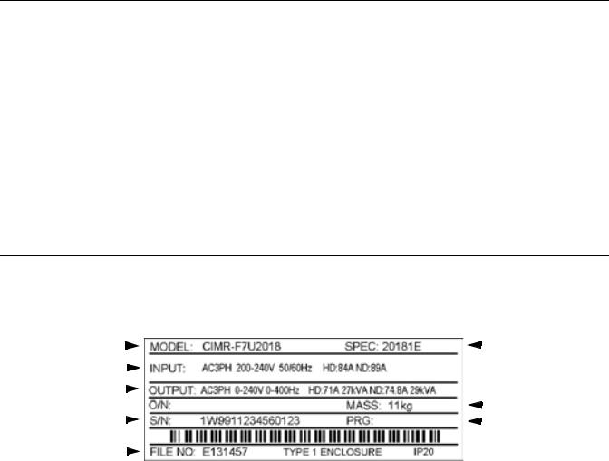
Nameplate Information
A nameplate is attached to the right side of each Drive. The following nameplate is an example for a standard Drive.
Drive Model Number |
|
|
|
|
|
|
|
|
|
|
|
|
Drive Spec Number |
|
|
|
|
|
|
|
|||||||
Input Power Rating |
|
|
|
|
|
|
|
|
|||||
|
|
|
|
|
|
|
|||||||
Output Power Rating |
|
|
|
|
|
|
|
Weight |
|||||
|
|
|
|
|
|||||||||
Serial Number |
|
|
|
|
|
|
|
|
|
|
|
||
|
|
|
|
|
|
|
|
|
|
|
|||
|
|
|
|
|
|
Software Number |
|||||||
|
|
|
|
||||||||||
|
|
|
|
|
|
|
|
|
|
|
|||
UL File Number |
|
|
|
|
|
||||||||
|
|
|
|
||||||||||
Note: The Drive Model Number, Drive Spec Number, Software Number, and Serial Number are required to completely identify a Drive. HD - Heavy Duty; ND - Normal Duty
Fig 1.1 F7 Drive Nameplate
Physical Installation 1 - 3

Drive Model Numbers
The model number on the nameplate indicates the design specification, voltage, and rating of the Drive in alphanumeric codes.
|
|
|
|
|
CIMR – F7 U 2 0 2 2 |
|
||||||
|
|
AC Drive |
|
|
|
|
|
|
|
|
|
|
|
|
|
|
|||||||||
|
|
F7 Family |
|
|
|
|
|
|
|
|||
|
|
|
|
|
|
|
|
|
||||
|
|
|
|
|
|
|
|
|
|
|
|
|
|
|
No. |
|
|
Spec |
|
|
|
|
Rating |
||
|
|
|
|
|
|
|||||||
|
|
|
|
|
|
|
|
|||||
|
|
U |
|
UL Specification |
|
|
|
|
|
|||
|
|
|
|
|
|
|
|
|
|
|
|
|
No. |
|
|
Voltage |
|
|
|
|
|
||||
|
|
|
|
|
|
|||||||
2 |
|
|
3-phase, 208-240Vac |
|
|
|
|
|
||||
4 |
|
|
3-phase, 480Vac |
|
|
|
|
|
||||
Fig 1.2 Drive Model Number Structure
Drive Enclosure and Revision Code
The SPEC number on the nameplate indicates the voltage, Drive rating, enclosure type, and the revision code of the Drive in alphanumeric codes. The SPEC number for Drives that have custom features, i.e. CASE software, will have a SPEC number that indicates the custom features installed.
2 0 2 2 1 E
No. |
Voltage |
|
|
|
|
|
|
|
|
Hardware Revision |
|
|||
|
|
|
|
|
|
|
|
|||||||
|
|
|
|
|
|
|
|
|||||||
2 |
3-phase, 208 - 240Vac |
|
|
|
|
|
|
|
|
|
|
|
|
|
4 |
3-phase, 480Vac |
|
|
|
|
|
|
|
|
|
|
|
|
|
|
|
|
|
|
|
|
|
|
|
|
|
|
|
|
|
|
Rating |
|
|
|
|
|
|
No. |
|
|
Enclosure Type |
||
|
|
|
|
|
|
|
||||||||
|
|
|
|
|
|
|
0 |
|
|
Open chassis (IEC IP00) |
|
|||
|
|
|
|
|
|
|
|
1 |
|
|
NEMA Type 1 (IEC IP20) |
|||
|
|
|
|
|
|
|
|
|
|
|
|
|
|
|
Fig 1.3 SPEC Number Structure
Open Chassis Type (IEC IP00)
Protected so that parts of the human body cannot reach electrically charged parts from the front when the Drive is mounted in a control panel, also called protected chassis.
TERMS NEMA Type 1 (IEC IP20)
The Drive is shielded from the exterior, and can thus be mounted to the interior wall of a building
(not necessarily enclosed in a control panel). The protective structure conforms to the standards of NEMA 1 in the USA. All protective covers (Fig 1.4 and Fig 1.6) must be installed to conform with IEC IP20 and NEMA Type 1 requirements.
Physical Installation 1 - 4
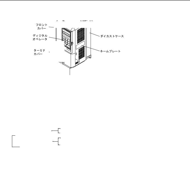
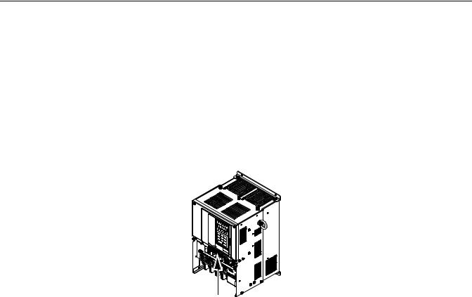
Component Names
Models CIMR-F7U20P4 thru 2018 and 40P4 thru 4018
The external appearance, component names, and terminal arrangement of the Drive are shown in Fig 1.4 and 1.5.
Top protective cover [Required for NEMA Type 1 (IEC IP20)]
Front cover
Digital Operator
Mounting hole
Die-cast Heat Sink
|
|
|
Terminal cover |
|
Nameplate |
|
|
|
Bottom protective cover
{Control circuit terminal layout label
Control circuit terminals
See Fig. 2.3 for actual terminal layout
Fig 1.4 Drive Appearance
Main circuit terminals
Charge indicator
|
|
|
Ground terminal |
|
Ground terminal |
|
|
|
Fig 1.5 Terminal Arrangement (Terminal Cover Removed)
Physical Installation 1 - 5
Models CIMR-F7U2022 thru 2110 and 4030 thru 4300
The external appearance, component names, and terminal arrangement of the Drive are shown in Fig 1.6 and 1.7.
|
holes |
|
Mountingting holes |
Drive cover |
|
Drive cover |
|
Front cover |
Cooling fan |
Cooling fan |
|
Front cover |
|
DigitalOperator |
|
Terminal cover |
Nameplate |
Nameplate |
|
Terminal cover |
|
Fig 1.6 Drive Appearance
{Control circuit terminal layout label  Control circuit terminals
See Fig. 2.3 for actual terminal layout
Main circuit terminals
Ground terminal 
 Charge indicator
Ground terminal
Fig 1.7 Terminal Arrangement (Terminal Cover Removed)
Physical Installation 1 - 6

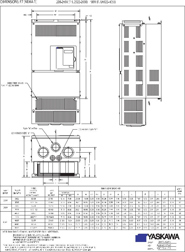
Exterior and Mounting Dimensions
DIMENSIONS: F7 (NEMA 1) 208-240V (F7U20P4-2018) 480V (F7U40P4-4018)
Physical Installation |
1 - 7 |
Physical Installation 1 - 8
Physical Installation |
1 - 9 |
Physical Installation |
1 - 10 |

Checking and Controlling the Installation Site
Install the Drive as described below and maintain optimum conditions.
Installation Site
Install the Drive to a non-combustible surface under the following conditions in UL Pollution Degree 2 environments. This excludes wet locations where pollution may become conductive due to moisture, and locations containing conductive foreign matter.
|
Table 1.3 Installation Site Specifications |
|
|
|
|
|
|
Type |
Ambient Operating Temperature |
Humidity |
Plenum Rated |
NEMA Type 1 |
14°F to 104°F (-10 to +40°C) |
95% RH or less (no condensation) |
Yes |
|
|
|
|
Open Chassis |
14°F to 113°F (-10 to +45°C) |
95% RH or less (no condensation) |
No |
|
|
|
|
Protective covers are attached to the top and bottom of the Drive. It is recommended to remove the protective covers before operating a NEMA Type 1 Drive (Models CIMR-F7U2030/4055 and smaller) in a panel to obtain the 113° (45°C) ambient operating temperature.
Observe the following precautions when installing the Drive. Make sure to install:
•in a clean location which is free from oil mist and dust.
•in an environment where metal shavings, oil, water, or other foreign materials do not get into the Drive.
•in a location free from radioactive materials and combustible materials (e.g. wood).
•in a location free from harmful gases and liquids.
•in a location free from excessive vibration.
•in a location free from chlorides.
•in a location away from direct sunlight.
Controlling the Ambient Temperature
To enhance the reliability of operation, the Drive should be installed in an environment free from extreme temperature variation. If the Drive is installed in an enclosure, use a cooling fan or air conditioner to maintain the internal air temperature below 113°F (45°C).
Protecting the Drive from Foreign Matter
During Drive installation and project construction, it is possible to have foreign matter such as metal shavings or wire clippings fall inside the Drive. To prevent foreign matter from falling into the Drive, place a temporary cover over the Drive.
Always remove the temporary cover from the Drive before start-up. Otherwise, ventilation will be reduced, causing the Drive to overheat.
Physical Installation 1 - 11
Installation Orientation and Clearances
Install the Drive vertically so as not to reduce the cooling efficiency. When installing the Drive, always provide the following installation clearances to allow normal heat dissipation and air flow. Ensure that the heatsink is against a closed surface to avoid diverting cooling air around the heatsink.
1.97in *1 (50mm) minimum |
4.75in *2 (120mm) minimum |
|
Air
1.2in |
|
1.2in |
|
||
|
|
||||
(30.5mm) minimum |
|
|
(30.5mm) minimum |
4.75in (120mm) minimum |
|
|
|||||
1.97in (50mm) minimum |
|
|
Air |
||
Horizontal Clearance |
|
|
Vertical Clearance |
||
*1 For Drive models F7U2110, F7U4160, and F7U4220, this clearance dimension is 4.75in (120mm) minimum. For Drive model F7U4300, this clearance dimension is 11.8in (300mm) minimum.
All other models require 1.97in (50mm) minimum.
*2 For Drive model F7U4300, this clearance dimension is 11.8in (300mm) minimum. All other models require 4.75in (120mm) minimum.
Fig 1.8 Drive Installation Orientation and Clearance
1.The same clearance is required horizontally and vertically for both Open Chassis (IP00) and NEMA Type 1 Drives.
IMPORTANT 2. Always remove the top and bottom protection covers before installing a CIMR-F7U2018/ 4018 and smaller Drive in a panel.
3.Always provide enough clearance for lifting eye bolts and the main circuit wiring when installing a CIMR-F7U2022/4030 and larger Drive in a panel.
Physical Installation 1 - 12
Removing and Attaching the Terminal Cover
Remove the terminal cover to connect cables to the control circuit and main circuit terminals.
Removing the Terminal Cover
Models CIMR-F7U20P4 thru 2018 and 40P4 thru 4018
Loosen the screw at the bottom of the terminal cover, press in on the sides of the terminal cover in the directions of arrows 1, and then lift up on the terminal in the direction of arrow 2.
1
2
1
Fig 1.9 Removing the Terminal Cover
Models CIMR-F7U2022 thru 2110 and 4030 thru 4300
Loosen the screws on the left and right at the top of the terminal cover, pull down the terminal cover in the direction of arrow 1, and then lift up on the terminal cover in the direction of arrow 2.
 1
1
2
Fig 1.10 Removing the Terminal Cover
Attaching the Terminal Cover
After wiring the terminal block, attach the terminal cover by reversing the removal procedure.
For Models CIMR-F7U2018/4018 and smaller, insert the tab on the top of the terminal cover into the groove on the Drive, and press in on the bottom of the terminal cover until it clicks into place.
For Drives CIMR-F7U2022/4030 and larger, insert the tab on the top of the terminal cover into the groove on the Drive, and secure the terminal cover by lifting it up toward the top of the Drive.
Physical Installation 1 - 13
Removing/Attaching the Digital Operator and Front Cover
Models CIMR-F7U20P4 thru 2018 and 40P4 thru 4018
For Models CIMR-F7U2018/4018 and smaller, remove the terminal cover and then use the following procedures to remove the Digital Operator and front cover.
Removing the Digital Operator
Press on the side of the Digital Operator in the direction of arrow 1 to unlock, then lift the Digital Operator in the direction of arrow 2 to remove it as shown in Fig 1.11.
2 1
Fig 1.11 Removing the Digital Operator
Removing the Front Cover
Press the left and right sides of the front cover in the direction of arrows 1 and lift the bottom of cover in the direction of arrow 2 to remove it as shown in Fig 1.12.
1
2  1
1
Fig 1.12 Removing the Front Cover
Mounting the Front Cover
Mount the front cover to the Drive by performing the steps to remove the front cover in reverse order.
1.Do not mount the front cover with the Digital Operator attached as this may cause the Digital Operator to malfunction due to improper mating with its connector.
2.Insert the tab of the upper part of the front cover into the groove of the Drive and press the lower part of the front cover onto the Drive until it snaps into place.
Physical Installation 1 - 14

Mounting the Digital Operator
After attaching the front cover, mount the Digital Operator onto the Drive using the following procedure:
1.Hook the Digital Operator at A (two locations) on the left side of the opening on the front cover by moving in the direction of arrow 1 as shown in the following illustration.
2.Press the Digital Operator in the direction of arrow 2 until it snaps in place at B (two locations).
A
1 |
|
B |
|
|
|
2 |
|
|
|
|
|
|
|
Fig 1.13 Mounting the Digital Operator
1.Do not remove or attach the Digital Operator and do not mount or remove the front cover using methods other than those described above, or damage to the Digital Operator or Drive may occur.
IMPORTANT 2. Never attach the front cover to the Drive with the Digital Operator already attached. Damage to the Digital Operator may occur. Always attach the front cover to the Drive first, and then attach the Digital Operator to the front cover.
Physical Installation 1 - 15
Models CIMR-F7U2022 thru 2110 and 4030 thru 4300
For Models CIMR-F7U2022/4030 and larger, remove the terminal cover and then use the following procedures to remove the Digital Operator and front cover.
Removing the Digital Operator
Use the same procedure for Models CIMR-F7U20P4 thru 2018 and 40P4 thru 4018.
Removing the Front Cover
Loosen all screws on the front cover. Lift up at the location labelled 1 at the top of the control circuit terminal card and move in the direction of arrow 2.
2
1
Fig 1.14 Removing the Front Cover
Mounting the Front Cover
Attach the front cover by reversing the procedure to remove it.
1.Confirm that the Digital Operator is not mounted on the front cover. If the cover is attached while the Digital Operator is mounted to it, the Digital Operator may malfunction due to improper mating with its connector.
2.Insert the tab on the top of the front cover into the slot on the Drive and press in on the cover until it clicks into place on the Drive.
Mounting the Digital Operator
Use the same procedure for Models CIMR-F7U20P4 thru 2018 and 40P4 thru 4018.
Physical Installation 1 - 16

Chapter 2
Electrical Installation
This chapter describes wiring terminals, main circuit terminal connections, main circuit terminal wiring specifications, control circuit terminals, and control circuit wiring specifications.
Terminal Block Configuration ............................................ |
2-2 |
Wiring Main Circuit Terminals ........................................... |
2-3 |
Control Wiring ................................................................. |
2-20 |
Electromagnetic Compatibility (EMC) ............................. |
2-26 |
Installing and Wiring Option Boards................................ |
2-30 |
Electrical Installation 2 - 1

Terminal Block Configuration
The wiring terminals are shown in Fig 2.1, Fig 2.2 and Fig 2.3.
Control circuit terminal layout label 
Control circuit terminals
Ground terminal
See Fig. 2.3 below for actual terminal layout
Ground terminal
Main circuit terminals
Charge indicator
Ground terminal
Fig 2.1 Terminal Configuration for Models CIMR-F7U2018/4018 and Smaller
Control circuit terminal  layout label
Control circuit terminals 
See Fig. 2.3 below for actual terminal layout
Main circuit terminals
Ground terminal 
Charge indicator
 Ground terminal
Fig 2.2 Terminal Configuration for Models CIMR-F7U2022/4022 and Larger
|
|
|
|
|
|
|
|
|
|
|
|
|
|
|
|
|
|
|
|
|
|
|
|
|
|
|
|
|
|
|
|
|
|
|
|
|
|
|
|
|
|
|
|
|
|
|
|
|
|
|
|
SN |
SC |
SP |
A1 |
A2 |
+V |
AC |
-V |
|
A3 |
MP |
AC |
RP |
R+ |
|
R- |
|
|
M5 |
M6 |
MA |
MB |
MC |
|
|
|
|
|||||||||||||||||||
|
|
|
|
|
|
|
|
|
|
|
|
|
|
|
|
|
|
|
|
|
|
|
|
|
|
|
|
|
|
|
|
|
|
|
|
|
|
|
|
|
|
|
|
|
|
|
|
|
|
E(G) |
|
|
S1 |
S2 |
S3 |
S4 |
S5 |
S6 |
S7 |
|
S8 |
FM |
AC |
AM |
IG |
S+ |
|
S- |
|
|
M3 |
M4 |
M1 |
|
|
M2 |
|
E(G) |
|
||||||||||||||||||
|
|
|
|
|
|
|
|
|
|
|
|
|
|
|
|
|
|
|
|
|
|
|
|
|
|
|
|
|
|
|
|
|
|
|
|
|
|
|
|
|
|
|
|
|
|
|
|
|
|
|
|
|
|
|
|
|
|
|
|
|
|
|
|
|
|
|
|
|
|
|
|
|
|
|
|
|
|
|
|
|
|
|
|
|
|
|
|
|
|
|
|
|
|
|
|
|
|
Fig 2.3 Control Circuit Terminal Layout
Electrical Installation 2 - 2

Wiring Main Circuit Terminals
Applicable Wire Sizes and Closed-loop Connectors
Select the appropriate wires and crimp terminals from Table 2.1 and Table 2.2. Refer to instruction manual TOE-C726-2 for Braking Resistor Unit and Braking Unit wire sizes.
Table 2.1 208-240Vac Wire Sizes and Connector Specifications
|
|
|
|
|
|
|
|
|
|
|
|
|
|
|
|
|
Clamping |
Possible Wire |
Recommended |
|
Drive Model |
|
Terminal Symbol |
|
|
Terminal |
Torque |
Sizes AWG |
Wire Size AWG |
Wire |
|||||||||||
CIMR-F7U |
|
|
|
Screws |
lb. in. |
(mm2) |
(mm2) |
Type |
||||||||||||
|
|
|
|
|
|
|
|
|
|
|
|
|
|
|
||||||
|
|
|
|
|
|
|
|
|
|
|
|
|
|
|
|
|
(N•m) |
*1 |
*2 |
|
|
R/L1, S/L2, T/L3, |
|
|
|
|
, |
|
|
1, |
2, B1, B2 |
|
10.6 to 13.2 |
14 to 10 |
14 |
|
|||||
|
|
|
|
|
||||||||||||||||
20P4 |
|
U/T1, V/T2, W/T3 |
|
|
M4 |
|
||||||||||||||
|
|
|
(1.2 to 1.5) |
(2 to 5.5) |
(2) |
|
||||||||||||||
|
|
|
|
|
|
|
|
|
|
|
|
|
|
|
|
|
|
|||
|
|
|
|
|
|
|
|
|
|
|
|
|
|
|
|
|
|
|
||
|
R/L1, S/L2, T/L3, |
|
|
|
|
, |
|
|
1, |
2, B1, B2 |
|
10.6 to 13.2 |
14 to 10 |
14 |
|
|||||
|
|
|
|
|
||||||||||||||||
20P7 |
|
U/T1, V/T2, W/T3 |
|
|
M4 |
|
||||||||||||||
|
|
|
(1.2 to 1.5) |
(2 to 5.5) |
(2) |
|
||||||||||||||
|
|
|
|
|
|
|
|
|
|
|
|
|
|
|
|
|
|
|||
|
|
|
|
|
|
|
|
|
|
|
|
|
|
|
|
|
|
|
||
|
R/L1, S/L2, T/L3, |
|
|
|
|
, |
|
|
1, |
2, B1, B2 |
|
10.6 to 13.2 |
14 to 10 |
14 |
|
|||||
|
|
|
|
|
||||||||||||||||
21P5 |
|
U/T1, V/T2, W/T3 |
|
|
M4 |
|
||||||||||||||
|
|
|
(1.2 to 1.5) |
(2 to 5.5) |
(2) |
|
||||||||||||||
|
|
|
|
|
|
|
|
|
|
|
|
|
|
|
|
|
|
|||
|
|
|
|
|
|
|
|
|
|
|
|
|
|
|
|
|
|
|
||
|
R/L1, S/L2, T/L3, |
|
|
|
|
, |
|
|
1, |
2, B1, B2 |
|
10.6 to 13.2 |
14 to 10 |
14 |
|
|||||
|
|
|
|
|
||||||||||||||||
22P2 |
|
U/T1, V/T2, W/T3 |
|
|
M4 |
|
||||||||||||||
|
|
|
(1.2 to 1.5) |
(2 to 5.5) |
(2) |
|
||||||||||||||
|
|
|
|
|
|
|
|
|
|
|
|
|
|
|
|
|
|
|||
|
|
|
|
|
|
|
|
|
|
|
|
|
|
|
|
|
|
|
|
|
|
R/L1, S/L2, T/L3, |
|
|
, |
|
|
1, |
2, |
B1, B2 |
|
10.6 to 13.2 |
12 to 10 |
12 |
|
||||||
|
|
|
|
|||||||||||||||||
23P7 |
|
U/T1, V/T2, W/T3 |
|
|
M4 |
|
||||||||||||||
|
|
|
(1.2 to 1.5) |
(3.5 to 5.5) |
(3.5) |
|
||||||||||||||
|
|
|
|
|
|
|
|
|
|
|
|
|
|
|
|
|
|
|||
|
|
|
|
|
|
|
|
|
|
|
|
|
|
|
|
|
|
|
|
|
|
R/L1, S/L2, T/L3, |
|
|
, |
|
|
1, |
2, |
B1, B2 |
|
10.6 to 13.2 |
12 to 10 |
10 |
|
||||||
|
|
|
|
|||||||||||||||||
25P5 |
|
U/T1, V/T2, W/T3 |
|
|
M4 |
|
||||||||||||||
|
|
|
(1.2 to 1.5) |
(3.5 to 5.5) |
(5.5) |
|
||||||||||||||
|
|
|
|
|
|
|
|
|
|
|
|
|
|
|
|
|
|
|||
|
|
|
|
|
|
|
|
|
|
|
|
|
|
|
|
|
|
|
||
|
R/L1, S/L2, T/L3, |
|
|
, |
|
|
1, |
2, B1, B2 |
|
21.99 |
8 to 6 |
8 |
|
|||||||
|
|
|
|
|||||||||||||||||
27P5 |
|
U/T1, V/T2, W/T3 |
|
|
M5 |
|
||||||||||||||
|
|
|
(2.5) |
(8 to 14) |
(8) |
|
||||||||||||||
|
|
|
|
|
|
|
|
|
|
|
|
|
|
|
|
|
|
|||
|
|
|
|
|
|
|
|
|
|
|
|
|
|
|
|
|
|
|
|
|
|
R/L1, S/L2, T/L3, |
|
|
|
|
, |
|
|
1, |
2, B1, B2 |
|
|
|
4 |
|
|||||
2011 |
|
|
|
|
M5 |
21.99 |
6 to 4 |
(22) |
600Vac |
|||||||||||
|
U/T1, V/T2, W/T3 |
|
|
(2.5) |
(14 to 22) |
6 |
UL Approved |
|||||||||||||
|
|
|
|
|
||||||||||||||||
|
|
|
|
|
|
|
|
|
|
|
|
|
|
|
|
|
|
|
(14) |
vinyl-sheathed |
|
|
|
|
|
|
|
|
|
|
|
|
|
|
|
|
|
|
|
|
or equivalent |
|
R/L1, S/L2, T/L3, |
|
|
, |
1, |
2 |
|
|
|
3 |
||||||||||
|
|
|
|
|
|
|
||||||||||||||
|
|
|
M6 |
35.2 to 43.99 |
4 to 2 |
(30) |
|
|||||||||||||
|
|
U/T1, V/T2, W/T3 |
|
|
(4.0 to 5.0) |
(22 to 38) |
4 |
|
||||||||||||
|
|
|
|
|
|
|||||||||||||||
2015 |
|
|
|
|
|
|
(22) |
|
||||||||||||
|
|
|
|
|
|
|
|
|
|
|
|
|
|
|
|
|
|
|
||
|
|
|
|
B1, B2 |
|
|
|
|
M5 |
21.99 |
8 to 6 |
Application |
|
|||||||
|
|
|
|
|
|
|
|
|
|
|||||||||||
|
|
|
|
|
|
|
|
|
(2.5) |
(8 to 14) |
Dependent |
|
||||||||
|
|
|
|
|
|
|
|
|
|
|
|
|
|
|
|
|
|
|||
|
|
|
|
|
|
|
|
|
|
|
|
|
|
|
|
M6 |
35.2 to 43.99 |
4 |
4 |
|
|
|
|
|
|
|
|
|
|
|
|
|
|
|
|
|
(4.0 to 5.0) |
(22) |
(22) |
|
|
|
|
|
|
|
|
|
|
|
|
|
|
|
|
|
|
|
|
|||
|
R/L1, S/L2, T/L3, |
|
|
, |
1, |
2 |
|
|
|
2 |
|
|||||||||
|
|
|
M8 |
79.2 to 87.97 |
3 to 2 |
(38) |
|
|||||||||||||
|
|
U/T1, V/T2, W/T3 |
|
|
(9.0 to 10.0) |
(30 to 38) |
3 |
|
||||||||||||
|
|
|
|
|
|
|||||||||||||||
2018 |
|
|
|
|
|
|
(30) |
|
||||||||||||
|
|
|
|
|
|
|
|
|
|
|
|
|
|
|
|
|
|
|
||
|
|
|
|
B1, B2 |
|
|
|
|
M5 |
21.99 |
8 to 6 |
Application |
|
|||||||
|
|
|
|
|
|
|
|
|
|
|||||||||||
|
|
|
|
|
|
|
|
|
(2.5) |
(8 to 14) |
Dependent |
|
||||||||
|
|
|
|
|
|
|
|
|
|
|
|
|
|
|
|
|
|
|||
|
|
|
|
|
|
|
|
|
|
|
|
|
|
|
|
M6 |
35.2 to 43.99 |
4 |
4 |
|
|
|
|
|
|
|
|
|
|
|
|
|
|
|
|
|
(4.0 to 5.0) |
(22) |
(22) |
|
|
|
|
|
|
|
|
|
|
|
|
|
|
|
|
|
|
|
|
|||
|
R/L1, S/L2, T/L3, |
|
|
, |
|
|
|
|
1, R1/L11, S1/L21, T1/L31 |
|
|
|
1 |
|
||||||
|
|
|
|
|
|
|
M8 |
79.2 to 87.97 |
N/A |
(50) |
|
|||||||||
|
U/T1, V/T2, W/T3, |
|
|
(9.0 to 10.0) |
2 |
|
||||||||||||||
|
|
|
|
|
|
|||||||||||||||
2022 |
|
|
|
|
|
(38) |
|
|||||||||||||
|
|
|
|
|
|
|
|
|
|
|
|
|
|
|
|
|
|
|
||
|
|
|
|
3 |
|
|
|
|
M6 |
35.2 to 43.99 |
N/A |
Application |
|
|||||||
|
|
|
|
|
|
|
|
|
|
|||||||||||
|
|
|
|
|
|
|
|
|
(4.0 to 5.0) |
Dependent |
|
|||||||||
|
|
|
|
|
|
|
|
|
|
|
|
|
|
|
|
M8 |
79.2 to 87.97 |
N/A |
4 |
|
|
|
|
|
|
|
|
|
|
|
|
|
|
|
|
|
(9.0 to 10.0) |
(22) |
|
||
|
|
|
|
|
|
|
|
|
|
|
|
|
|
|
|
|
|
|
||
|
R/L1, S/L2, T/L3, |
|
|
, |
1 U/T1, |
M8 |
79.2 to 87.97 |
N/A |
1/0 |
|
||||||||||
|
|
|
|
|||||||||||||||||
|
V/T2, W/T3, R1/L11, S1/L21, T1/L31 |
|
(9.0 to 10.0) |
|
(60) |
|
||||||||||||||
2030 |
|
|
|
|
3 |
|
|
|
|
M6 |
35.2 to 43.99 |
N/A |
Application |
|
||||||
|
|
|
|
|
|
|
|
|
(4.0 to 5.0) |
Dependent |
|
|||||||||
|
|
|
|
|
|
|
|
|
|
|
|
|
|
|
|
M8 |
79.2 to 87.97 |
N/A |
4 |
|
|
|
|
|
|
|
|
|
|
|
|
|
|
|
|
|
(9.0 to 10.0) |
(22) |
|
||
|
|
|
|
|
|
|
|
|
|
|
|
|
|
|
|
|
|
|
||
Electrical Installation 2 - 3
Loading...