


 Loading...
F7 Drive
Programming Manual
|
|
|
|
|
|
|
|
Model: CIMR-F7U |
Document Number: TM.F7.02 |
|
|
|
|
|
|
|
|

Warnings and Cautions
This Section provides warnings and cautions pertinent to this product, that if not heeded, may result in personal injury, fatality, or equipment damage. Yaskawa is not responsible for consequences of ignoring these instructions.

 WARNING
YASKAWA manufactures component parts that can be used in a wide variety of industrial applications. The selection and application of YASKAWA products remain the responsibility of the equipment designer or end user. YASKAWA accepts no responsibility for the way its products are incorporated into the final system design. Under no circumstances should any YASKAWA product be incorporated into any product or design as the exclusive or sole safety control. Without exception, all controls should be designed to detect faults dynamically and fail safely under all circumstances. All products designed to incorporate a component part manufactured by YASKAWA must be supplied to the end user with appropriate warnings and instructions as to that part’s safe use and operation. Any warnings provided by YASKAWA must be promptly provided to the end user. YASKAWA offers an express warranty only as to the quality of its products in conforming to standards and specifications published in the YASKAWA manual. NO OTHER WARRANTY, EXPRESS OR IMPLIED, IS OFFERED. YASKAWA assumes no liability for any personal injury, property damage, losses, or claims arising from misapplication of its products.

 WARNING
•Read and understand this manual before installing, operating, or servicing this Drive. All warnings, cautions, and instructions must be followed. All activity must be performed by qualified personnel. The Drive must be installed according to this manual and local codes.
•Do not connect or disconnect wiring while the power is on. Do not remove covers or touch circuit boards while the power is on. Do not remove or insert the digital operator while power is on.
•Before servicing, disconnect all power to the equipment. The internal capacitor remains charged even after the power supply is turned off. The charge indicator LED will extinguish when the DC bus voltage is below 50Vdc. To prevent electric shock, wait at least five minutes after all indicators are OFF and measure DC bus voltage level to confirm safe level.
•Do not perform a withstand voltage test on any part of the unit. This equipment uses sensitive devices and may be damaged by high voltage.

 WARNING
•The Drive is suitable for circuits capable of delivering not more than 100,000 RMS symmetrical Amperes, 240Vac maximum (200V Class) and 480Vac maximum (400V Class). Install adequate branch circuit short circuit protection per applicable codes. Failure to do so may result in equipment damage and/or personal injury. Refer to Appendix E for further details.
•Do not connect unapproved LC or RC interference suppression filters, capacitors, or overvoltage protection devices to the output of the Drive. These devices may generate peak currents that exceed Drive specifications.
i
•To avoid unnecessary fault displays caused by contactors or output switches placed between Drive and motor, auxiliary contacts must be properly integrated into the control logic circuit.
•YASKAWA is not responsible for any modification of the product made by the user; doing so will void the warranty. This product must not be modified.
•Verify that the rated voltage of the Drive matches the voltage of the incoming power supply before applying power.
•To meet CE directives, proper line filters and proper installation are required.
•Some drawings in this manual may be shown with protective covers or shields removed, to describe details. These must be replaced before operation.
•Observe electrostatic discharge procedures when handling circuit boards to prevent ESD damage.
•The equipment may start unexpectedly upon application of power. Clear all personnel from the Drive, motor, and machine area before applying power. Secure covers, couplings, shaft keys, and machine loads before energizing the Drive.
•Please do not connect or operate any equipment with visible damage or missing parts. The operating company is responsible for any injuries or equipment damage resulting from failure to heed the warnings in this manual.
Intended Use
Drives are intended for installation in electrical systems or machinery.
The Drives are designed and manufactured in accordance with applicable UL and cUL standards, and CE directives.
For use in the European Union, the installation in machinery and systems must conform to the following product standards of the Low Voltage Directive:
EN 50178: 1997-10, Electronic Equipment for Use in Power Installations
EN 60201-1: 1997-12 Machine Safety and Equipping with Electrical Devices
Part 1: General Requirements (IEC 60204-1:1997)
EN 61010: 1997-11 Safety Requirements for Information Technology Equipment (IEC 950:1991 + A1:1992 + A2:1993 + A3:1995 + A4:1996, modified)
The F7 series Drives comply with the provisions of the Low Voltage Directive 73/23/EEC as amended by 93/68/EEC. These Drives conform to the following standard: EN 50178: 1997-10.
Your supplier or Yaskawa representative must be contacted when using leakage current circuit breaker in conjunction with frequency inverters.
In certain systems it may be necessary to use additional monitoring and safety devices in compliance with the relevant safety and accident prevention regulations. The frequency inverter hardware must not be modified.
ii

Introduction
This section describes the applicability of the manual.
This manual is applicable to F7 Drives defined by model numbers of CIMR-F7U |
. |
The F7 Drive is a Pulse Width Modulated Drive for AC 3-Phase induction motors. This type of Drive is also known as an Adjustable Frequency Drive, Variable Frequency Drive, AC Drive, AFD, ASD, VFD, VSD, and Inverter. In this manual, the F7 Drive will be referred to as the “Drive”.
The LCD keypad/operator is equipped with local/remote functions, copy feature, 7 language choices, and 5 lines of display with 16 characters per line. User parameter settings can be recovered at any time via “user initialization” when enabled. Optional Drive Wizard software allows upload/download, as well as graphing and monitoring of Drive parameters from a PC for ease of Drive management.
This manual may describe trademarked equipment, which is the property of other companies, who are the registered owners.
Other Documents and Manuals are available to support special use or installation of this product. These documents may be provided with the product or upon request. Contact Yaskawa Electric America, Inc. as required. Documents may include the following:
TM.F7.02.Programming…Manual included on CD ROM with product
TM.F7.01.…Manual included on CD ROM with product
DriveWizard...Software and Manual…Included on CD ROM with product
Option Instructions… Included on CD ROM with product
This manual is subject to change as product improvements occur. The latest version of the manual can be obtained from the Yaskawa website: www.drives.com. The date shown on the rear cover is changed when revisions are made. The latest version of Drive software is also shown.
The Drive’s capacity is categorized based on two types of load characteristics: Heavy Duty and Normal Duty. See Table i.1 below for the differences between Heavy Duty and Normal Duty.
Table i.1 Drive Duty Selection
Parameter |
Rated Output |
Overload |
Current Limit |
Carrier |
|
Maximum Output |
C6-01 |
Current |
Capacity |
Frequency |
|
Frequency |
|
|
|
|||||
0: Heavy Duty |
Standard rating |
150% for 1 min. |
150% |
Low |
|
300Hz |
(default) |
(varies by model*) |
(2kHz) |
|
|||
|
|
|
|
|||
2: Normal Duty |
Extended rating |
Approx. 110% for 1 min. |
120% |
High |
|
400Hz |
(varies by model*) |
(varies by model*) |
(varies by model*) |
|
|||
|
|
|
|
|||
|
|
|
|
|
|
|
* See Drive Specifications |
|
|
|
|
|
|
This manual references the various Drive capacities according to its model number CIMR-F7U |
. See Drive |
|||||
Output Specifications Table i.2 and Table i.3 on the following pages for rated capacities and Drive specifications.
iii

Drive Output Specifications
The standard Drive specifications are listed in the following tables.
208-240Vac
|
|
|
|
|
|
Table i.2 208-240Vac Drive Specifications |
|
|
|
|
|
|
|
||||||||
|
|
|
|
|
|
|
208-240Vac |
|
|
|
|
|
|
|
|
208-230Vac |
|
|
|||
Model Number CIMR-F7U |
20P4 |
20P7 |
21P5 |
22P2 |
23P7 |
25P5 |
27P5 |
2011 |
2015 |
|
2018 |
2022 |
2030 |
2037 |
2045 |
2055 |
2075 |
2090 |
2110 |
||
|
|
Rated output |
1.2 |
1.6 |
2.7 |
3.7 |
5.7 |
8.8 |
12.0 |
17.0 |
22.0 |
|
27.0 |
32.0 |
44.0 |
55.0 |
69.0 |
82.0 |
110.0 |
130.0 |
|
|
|
capacity (kVA) |
|
|
|||||||||||||||||
|
|
|
|
|
|
|
|
|
|
|
|
|
|
|
|
|
|
|
|
|
|
|
|
Horsepower*2 |
0.5/0.75 |
2 |
2 |
3 |
5 |
7.5 |
10 |
15 |
20 |
|
25 |
30 |
40 |
50 |
60 |
75 |
100 |
125 |
|
|
|
Rated output |
3.2 |
4.2 |
7.0 |
9.6 |
15.2 |
23.0 |
31.0 |
45.0 |
58.0 |
|
71 |
85.0 |
115.0 |
145.0 |
180.0 |
215 |
283.0 |
346.0 |
|
|
1 |
current (A) |
|
|
|||||||||||||||||
|
|
|
|
|
|
|
|
|
|
|
|
|
|
|
|
|
|
|
|
||
|
* |
|
|
|
|
|
|
|
|
|
|
|
|
|
|
|
|
|
|
|
|
|
Duty |
Overload capacity*3 |
|
|
|
|
|
|
|
|
150 |
|
|
|
|
|
|
|
|
|
N/A |
|
|
|
|
|
|
|
|
|
|
|
|
|
|
|
|
|
|
|
|||
|
Heavy |
(% of rated output |
|
|
|
|
|
|
|
|
|
|
|
|
|
|
|
|
|
||
|
current for 60 sec.) |
|
|
|
|
|
|
|
|
|
|
|
|
|
|
|
|
|
|
|
|
|
|
|
|
|
|
|
|
|
|
|
|
|
|
|
|
|
|
|
|
|
|
|
|
Current limit (% of |
|
|
|
|
|
|
|
|
150 |
|
|
|
|
|
|
|
|
|
|
|
|
rated output current) |
|
|
|
|
|
|
|
|
|
|
|
|
|
|
|
|
|
|
|
|
|
|
|
|
|
|
|
|
|
|
|
|
|
|
|
|
|
|
|
|
|
|
|
Carrier frequency*4 |
|
|
|
|
|
|
|
|
2kHz |
|
|
|
|
|
|
|
|
|
|
|
|
Maximum output |
|
|
|
|
|
|
|
300.0Hz |
|
|
|
|
|
|
|
|
|
||
ratings |
|
frequency |
|
|
|
|
|
|
|
|
|
|
|
|
|
|
|
|
|||
|
|
|
|
|
|
|
|
|
|
|
|
|
|
|
|
|
|
|
|
||
|
Rated output |
1.4 |
1.8 |
3.0 |
4.1 |
6.4 |
8.8 |
12.0 |
18.0 |
23.0 |
|
29.0 |
34.0 |
44.0 |
62.0 |
73.0 |
82.0 |
120.0 |
140.0 |
160.0 |
|
|
capacity (kVA) |
|
|||||||||||||||||||
utput |
|
|
|
|
|
|
|
|
|
|
|
|
|
|
|
|
|
|
|
|
|
|
Horsepower*2 |
0.5/0.75 |
1 |
2 |
3 |
5 |
7.5 |
10 |
15 |
20 |
|
25 |
30 |
40 |
50/60 |
75 |
75 |
100/125 |
150 |
150 |
|
O |
|
|
|
|
|
|
|
|
|
|
|
|
|
|
|
|
|
|
|
|
|
|
|
Rated output |
3.6 |
4.6 |
7.8 |
10.8 |
16.8 |
23.0 |
31.0 |
46.2 |
59.4 |
|
74.8 |
88.0 |
115.0 |
162.0 |
192.0 |
215 |
312.0 |
360.0 |
415.0 |
|
|
current (A) |
|
||||||||||||||||||
|
*1 |
|
|
|
|
|
|
|
|
|
|
|
|
|
|
|
|
|
|
|
|
|
Overload capacity*3 |
|
|
|
|
|
|
|
|
|
|
|
|
|
|
|
|
|
|
|
|
|
Duty |
107 |
107 |
108 |
107 |
107 |
120 |
120 |
117 |
117 |
|
114 |
116 |
120 |
107 |
113 |
120 |
109 |
115 |
120 |
|
|
(% of rated output |
|
|||||||||||||||||||
|
Normal |
|
|||||||||||||||||||
|
Current limit (% of |
|
|
|
|
|
|
|
|
|
|
|
|
|
|
|
|
|
|
|
|
|
|
current for 60 sec.) |
|
|
|
|
|
|
|
|
|
|
|
|
|
|
|
|
|
|
|
|
|
rated output current) |
|
|
|
|
|
|
|
|
120 |
|
|
|
|
|
|
|
|
||
|
|
|
|
|
|
|
|
|
|
|
|
|
|
|
|
|
|
|
|
|
|
|
|
Carrier frequency |
10 |
10 |
10 |
8 |
10 |
15 |
15 |
8 |
10 |
|
10 |
10 |
10 |
5 |
5 |
8 |
2 |
2 |
2 |
|
|
(kHz)*5 |
|
||||||||||||||||||
|
|
|
|
|
|
|
|
|
|
|
|
|
|
|
|
|
|
|
|
|
|
|
|
Maximum output |
|
|
|
|
|
|
|
|
400.0Hz |
|
|
|
|
|
|
|
|
||
|
|
frequency |
|
|
|
|
|
|
|
|
|
|
|
|
|
|
|
|
|||
|
|
|
|
|
|
|
|
|
|
|
|
|
|
|
|
|
|
|
|
|
|
|
Maximum output voltage |
|
|
|
|
|
|
3-phase; 200, 208, 220, 230, or 240Vac |
|
|
|
|
|
|
|||||||
|
|
|
|
|
|
|
(Proportional to input voltage) |
|
|
|
|
|
|
||||||||
|
|
|
|
|
|
|
|
|
|
|
|
|
|
|
|||||||
*1 |
The difference between Heavy |
Duty ratings and the Normal Duty ratings for the Drive are the rated input and output current, overload capacity, carrier frequency, current limit, and |
|||||||||||||||||||
|
maximum output frequency. Parameter C6-01 must be set to value of “0” for Heavy Duty ratings and “2” for Normal Duty ratings. Factory default is Heavy Duty (C6-01=0). |
||||||||||||||||||||
*2 Horsepower ratings are based on 230V or 460V NEC Table 430.150. The maximum applicable motor output is given for a standard 4-pole motor. When selecting the actual motor and Drive, be sure that the Drive's rated output current is appropriate for the motor's rated current.
*3 Models 2110, 4220, 4300 have an overload rating of 120% of rated output current for 60 seconds. *4 2kHz is the Maximum carrier frequency value and default carrier frequency value for all models.
*5 Each value shown is the Maximum carrier frequency and default carrier frequency.
iv

480Vac
|
|
|
|
|
|
Table i.3 480Vac Drive Specifications |
|
|
|
|
|
|||||
Model Number CIMR-F7U |
40P4 |
40P7 |
41P5 |
42P2 |
43P7 |
44P0 |
|
45P5 |
47P5 |
4011 |
4015 |
4018 |
4022 |
|||
|
|
Rated output capacity(kVA) |
1.4 |
1.6 |
2.8 |
4.0 |
5.8 |
6.6 |
|
9.5 |
13.0 |
18.0 |
24.0 |
30.0 |
34.0 |
|
|
|
Horsepower*2 |
0.5/0.75 |
1 |
1.5/2 |
3 |
5 |
- |
|
7.5 |
10 |
15 |
20 |
25 |
30 |
|
|
|
Rated output current (A) |
1.8 |
2.1 |
3.7 |
5.3 |
7.6 |
8.7 |
|
12.5 |
17.0 |
24.0 |
31.0 |
39.0 |
45.0 |
|
|
*1 |
Overload capacity*3 |
|
|
|
|
|
|
|
|
|
|
|
|
|
|
|
(% of rated output |
|
|
|
|
|
|
150 |
|
|
|
|
|
|||
|
Duty |
|
|
|
|
|
|
|
|
|
|
|
||||
|
current for 60 sec.) |
|
|
|
|
|
|
|
|
|
|
|
|
|
||
|
Heavy |
|
|
|
|
|
|
|
|
|
|
|
|
|
||
|
Current limit*2 (% of |
|
|
|
|
|
|
150 |
|
|
|
|
|
|||
|
|
|
|
|
|
|
|
|
|
|
|
|
||||
|
|
rated output current) |
|
|
|
|
|
|
|
|
|
|
|
|||
|
|
|
|
|
|
|
|
|
|
|
|
|
|
|
||
|
|
Carrier frequency*4 |
|
|
|
|
|
2kHz |
|
|
|
|
|
|||
ngs |
|
Maximum output |
|
|
|
|
|
300.0Hz |
|
|
|
|
|
|||
|
frequency |
|
|
|
|
|
|
|
|
|
|
|
||||
rati |
|
|
|
|
|
|
|
|
|
|
|
|
|
|
|
|
utput |
|
Rated output capacity (kVA) |
1.4 |
1.6 |
2.8 |
4.0 |
5.8 |
6.6 |
|
9.5 |
13.0 |
21.0 |
26.0 |
30.0 |
38.0 |
|
|
Horsepower |
*2 |
0.5/0.75 |
1 |
1.5/2 |
3 |
5 |
- |
|
7.5 |
10 |
15/20 |
25 |
30 |
30 |
|
O |
|
|
|
|||||||||||||
|
|
Rated output current (A) |
1.8 |
2.1 |
3.7 |
5.3 |
7.6 |
8.7 |
|
12.5 |
17.0 |
27.0 |
34.0 |
40.0 |
50.4 |
|
|
*1 |
Overload capacity*3 |
|
|
|
|
|
|
|
|
|
|
|
|
|
|
|
Duty |
(% of rated output |
120 |
120 |
120 |
120 |
120 |
120 |
|
120 |
120 |
107 |
109 |
117 |
107 |
|
|
|
|
||||||||||||||
|
Normal |
current for 60 sec.) |
|
|
|
|
|
|
|
|
|
|
|
|
|
|
|
Current limit (% of |
|
|
|
|
|
|
120 |
|
|
|
|
|
|||
|
|
rated output current) |
|
|
|
|
|
|
|
|
|
|
|
|
|
|
|
|
Carrier frequency (kHz)*5 |
15 |
15 |
15 |
15 |
15 |
15 |
|
15 |
15 |
8 |
10 |
10 |
10 |
|
|
|
Maximum output |
|
|
|
|
|
400.0Hz |
|
|
|
|
|
|||
|
|
frequency |
|
|
|
|
|
|
|
|
|
|
|
|||
|
|
|
|
|
|
|
|
|
|
|
|
|
|
|
|
|
|
Maximum output voltage |
|
|
3-phase; 380, 400, 415, 440, 460, or 480Vac (Proportional to input voltage) |
|
|
||||||||||
Model Number CIMR-F7U |
4030 |
4037 |
4045 |
4055 |
4075 |
|
4090 |
|
4110 |
4132 |
4160 |
4185 |
4220 |
|
4300 |
|||
|
|
|
Rated output capacity(kVA) |
46.0 |
57.0 |
69.0 |
85.0 |
110.0 |
|
140.0 |
|
160.0 |
200.0 |
230.0 |
280.0 |
|
|
|
|
|
|
|
|
|
|
|
|
|
|
|
|
|
|
|
|
|
|
|
|
|
Horsepower*2 |
40 |
50 |
60 |
75 |
100 |
|
125/150 |
|
- |
200 |
250 |
300 |
|
|
|
|
|
|
Rated output current (A) |
60.0 |
75.0 |
91.0 |
112.0 |
150.0 |
|
180.0 |
|
216.0 |
260.0 |
304.0 |
370.0 |
|
|
|
|
*1 |
|
Overload capacity*3 |
|
|
|
|
|
150 |
|
|
|
|
|
|
|
|
|
|
Duty |
(% of rated output |
|
|
|
|
|
|
|
|
|
|
|
N/A |
||||
|
current for 60 sec.) |
|
|
|
|
|
|
|
|
|
|
|
|
|
||||
|
Heavy |
|
|
|
|
|
|
|
|
|
|
|
|
|
|
|||
|
|
Current Limit (% of |
|
|
|
|
|
150 |
|
|
|
|
|
|
|
|
||
|
|
|
rated output current) |
|
|
|
|
|
|
|
|
|
|
|
|
|
|
|
|
|
|
Carrier frequency*4 |
|
|
|
|
|
2kHz |
|
|
|
|
|
|
|
|
|
ings |
|
|
Maximum output |
|
|
|
|
300.0Hz |
|
|
|
|
|
|
|
|
||
|
|
frequency |
|
|
|
|
|
|
|
|
|
|
|
|
||||
rat |
|
|
|
|
|
|
|
|
|
|
|
|
|
|
|
|
|
|
|
|
Rated output capacity(kVA) |
51.0 |
59.0 |
73.0 |
95.0 |
120.0 |
|
140.0 |
|
180.0 |
200.0 |
230.0 |
315.0 |
390.0 |
|
510.0 |
|
utput |
|
|
|
|
|
|||||||||||||
|
|
|
|
|
|
|
|
|
|
|
|
|
|
|
|
|
|
|
|
|
Horsepower*2 |
40/50 |
60 |
75 |
100 |
125 |
|
150 |
|
200 |
- |
250 |
300/350 |
400/450 |
|
500+ |
|
O |
|
|
|
|
|
|
|
|
|
|
|
|
|
|
|
|
|
|
|
|
|
Rated output current (A) |
67.2 |
77.0 |
96.0 |
125.0 |
156.0 |
|
180.0 |
|
240.0 |
260.0 |
304.0 |
414.0 |
515.0 |
|
675.0 |
|
*1 |
|
Overload capacity*3 |
|
|
|
|
|
|
|
|
|
|
|
|
|
|
|
|
Duty |
(% of rated output |
107 |
117 |
114 |
108 |
115 |
|
120 |
|
108 |
120 |
120 |
107 |
118 |
|
120 |
|
|
Normal |
|
current for 60 sec.) |
|
|
|
|
|
|
|
|
|
|
|
|
|
|
|
|
|
Current Limit (% of |
|
|
|
|
|
|
|
120 |
|
|
|
|
|
|
||
|
|
|
rated output current) |
|
|
|
|
|
|
|
|
|
|
|
|
|
|
|
|
|
|
Carrier frequency (kHz)*5 |
8 |
8 |
8 |
5 |
5 |
|
8 |
|
5 |
5 |
5 |
2 |
2 |
|
2 |
|
|
|
Maximum output |
|
|
|
|
|
|
|
400.0Hz |
|
|
|
|
|
|
|
|
|
|
frequency |
|
|
|
|
|
|
|
|
|
|
|
|
|
||
|
|
|
|
|
|
|
|
|
|
|
|
|
|
|
|
|
|
|
|
Maximum output voltage |
|
|
3-phase, 380, 400, 415, 440, 460 or 480Vac (Proportional to input voltage) |
|
|
|
|||||||||||
*1 The difference between Heavy Duty ratings and the Normal Duty ratings for the Drive are the rated input and output current, overload capacity, carrier frequency, current limit, and maximum output frequency. Parameter C6-01 must be set to value of “0” for Heavy Duty ratings and “2” for Normal Duty ratings. Factory default is Heavy Duty (C6-01=0).
*2 Horsepower ratings are based on 230V or 460V NEC Table 430.150. The maximum applicable motor output is given for a standard 4-pole motor. When selecting the actual motor and Drive, be sure that the Drive's rated output current is appropriate for the motor's rated current.
*3 Models 2110, 4220, 4300 have an overload rating of 120% of rated output current for 60 seconds. *4 2kHz is the Maximum carrier frequency value and default carrier frequency value for all models.
*5 Each value shown is the Maximum carrier frequency and default carrier frequency.
v
Notes:
vi

F7 Programming
This Manual contains descriptions of all user accessible parameters contained in the Drive. Parameters are listed in alpha-numerical order. Parameter number and name, along with a detailed description and its settings are described on the following pages.
A1 Initialization...................................................................................... |
3 |
|
A2 User Parameters ............................................................................. |
5 |
|
b1 Sequence......................................................................................... |
6 |
|
b2 |
DC Braking .................................................................................... |
12 |
b3 |
Speed Search ................................................................................ |
14 |
b4 |
Delay Timers.................................................................................. |
18 |
b5 |
PID Function .................................................................................. |
18 |
b6 |
Reference Hold (Dwell).................................................................. |
23 |
b7 |
Droop Control ................................................................................ |
24 |
b8 |
Energy Savings Selection.............................................................. |
25 |
b9 |
Zero Servo ..................................................................................... |
26 |
C1 Accel/Decel ................................................................................... |
26 |
|
C2 S-Curve Acc/Dec........................................................................... |
29 |
|
C3 Motor-Slip Compensation.............................................................. |
30 |
|
C4 Torque Comp................................................................................. |
31 |
|
C5 ASR Tuning ................................................................................... |
32 |
|
C6 Carrier Frequency ......................................................................... |
35 |
|
d1 |
Preset References ......................................................................... |
37 |
d2 |
Reference Limits............................................................................ |
40 |
d3 |
Jump Frequencies ......................................................................... |
41 |
d4 Sequence....................................................................................... |
42 |
|
d5 |
Torque Control ............................................................................... |
43 |
d6 |
Field-Weakening............................................................................ |
49 |
E1 V/f Pattern ..................................................................................... |
50 |
|
E2 Motor Setup................................................................................... |
56 |
|
E3 V/f Pattern 2 .................................................................................. |
58 |
|
E4 Motor Setup 2................................................................................ |
60 |
|
F1 PG Option Setup ........................................................................... |
62 |
|
F2 AI-14 Setup.................................................................................... |
65 |
|
F3 DI-08, 16 Setup ............................................................................. |
65 |
|
F4 AO-08, 12 Setup............................................................................ |
66 |
|
F5 DO-02, 08 Setup............................................................................ |
67 |
|
F6 Communication Option Selection .................................................. |
68 |
|
H1 Digital Inputs.................................................................................. |
69 |
|
H2 Digital Outputs............................................................................... |
87 |
|
H3 Analog Inputs ................................................................................ |
96 |
|
H4 Analog Outputs ........................................................................... |
105 |
|
H5 Serial Communications Setup..................................................... |
111 |
|
H6 Pulse I/O Setup ........................................................................... |
114 |
|
Programming 1
L1 |
Motor Overload ............................................................................ |
115 |
L2 |
Momentary Power Loss Function ................................................ |
118 |
L3 |
Stall Prevention ............................................................................ |
120 |
L4 frequency reference Loss Detection ............................................ |
124 |
|
L5 |
Fault Restart ................................................................................ |
125 |
L6 |
Torque Detection.......................................................................... |
127 |
L7 |
Torque Limit ................................................................................. |
129 |
L8 |
Hardware Protection .................................................................... |
131 |
N1 Hunting Prevention...................................................................... |
134 |
|
N2 AFR Tuning ................................................................................. |
135 |
|
N3 High Slip Braking......................................................................... |
135 |
|
O1 Monitor Configuration.................................................................. |
137 |
|
O2 Key Selections ............................................................................ |
140 |
|
O3 Digital Operator Copy Function................................................... |
145 |
|
T1 Auto-Tuning ................................................................................. |
147 |
|
Appendix A - Parameters.................................................................. |
151 |
|
Programming 2
F7 Basic Programming Parameters
The initialization group contains parameters associated with initial set-up of the Drive. Parameters involving the display language, access levels, initialization and password are located in this group.
A1 Initialization
A1-00 Language Selection
Setting |
Description |
0 |
English (factory default) |
1 |
Japanese |
2 |
Deutsch |
3 |
Francais |
4 |
Italiano |
5 |
Espanol |
6 |
Portugues |
The setting of parameter A1-00 determines which international language the Drive will use to display non-numerical text. The A1-00 parameter will not be changed by an Initialization of the drive (A1-03= “1110: User Initialize”, “2220: 2-Wire Initial”, or “3330: 3-Wire Initial”).
If the Drive is accidentally set to a language unfamiliar to the operator, locating the parameter to change the operator language can be done by performing the following:
1.Press the MENU key until the “-ADV-” MENU is shown in the upper left corner of the digital operator.
2.Press the DATA/ENTER key to enter the programming menu. The first parameter shown is A1-00 (Select Language).
3.Press the DATA/ENTER key again and use the INCREASE and DECREASE arrow keys to choose the preferred language from the list below:
0 : English
1 : Japanese
2 : Deutsch (German)
3 : Francais (French)
4 : Italiano (Italian)
5 : Español (Spanish)
6 : Portuguės (Portuguese)
A1-01 Access Level Selection
Setting |
Description |
0 |
Operation Only |
1 |
User Level |
2 |
Advanced Level (factory default) |
A1-01 can be used to allow access to and permission to change all Drive parameters. If the Drive is programmed for Operation Only (A1-01= “0: Operation Only”), then only the Operation and the Programming menus are accessible. Within the Programming menu only parameters A1-01 and A1-04 are adjustable.
Programming 3
If A1-01 is configured for Advanced Access (A1-01= “2: Advanced Level”), then all menus and all parameters are shown. If the Access Level Selection is set to Advanced, all parameters should be adjustable unless:
1.The Drive parameters are password protected (A1-04) which will prevent access to A1-00 through A1-03 and all A2 parameters.
2.A digital input has been configured as a Program Lockout (H1-0X= 1B) is active.
3.During serial communication writing, if a parameter change is also attempted via the digital operator, a
“BUSY - WRITE PROTECTED” message will display. Parameter change will not be possible from the digital operator until an Enter command is received via the serial communication to finish the serial writing process.
A1-02 Control Method Selection
Setting |
Description |
0 |
V/f Control without PG |
1 |
V/f Control with PG |
2 |
Open Loop Vector (factory default) |
3 |
Flux Vector (Closed Loop Vector) |
The Control Method of the Drive can be selected in A1-02 to best suit the application.
V/f Control without PG - For general purpose and multiple motor applications.
V/f Control with PG - For general purpose applications requiring closed loop speed control.
Open Loop Vector - For applications requiring precise speed control, quick response, and higher torque at low speeds.
Flux Vector - For applications requiring very precise speed and torque control at wide speed range including zero speed. Uses an encoder feedback.
A1-03 Initialize Parameters
Setting |
Description |
0 |
No Initialize (factory default) |
1110 |
User Initialize |
2220 |
2-Wire Initialize |
3330 |
3-Wire Initialize |
The Drive can be set back to one of three default states via the A1-03 parameter.
1. User Initialization – 1110: The modified Drive parameters are returned to the values selected as user settings. User settings are stored when parameter o2-03= “1: Set Defaults”.
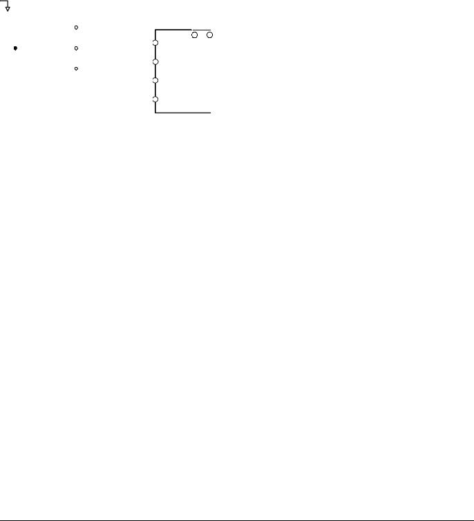
2. 2-Wire Initialization – 2220: The Drive parameters are returned to factory default values with digital inputs S1 and S2 configured as Forward Run and Reverse Run, respectively.
3. 3-Wire Initialization – 3330: The Drive parameters are returned to factory default values with digital inputs S1, S2, and S5 configured as Run, Stop, and Forward/Reverse respectively.
After an initialization is performed, parameter A1-03 will automatically be set back to 0.
Programming 4
|
|
|
|
|
|
|
|
|
Stop |
Operation |
|
|
|
|
|
|||||
|
|
|
S1 |
|
|
|
|
switch |
switch |
|
|
|
|
|
||||||
|
|
|
|
|
|
|
|
|
|
|
|
|||||||||
|
|
|
|
|
|
|
(NC contact) |
(NO contact) |
|
|
|
|
|
|||||||
|
|
|
|
|
|
FWD Run/Stop |
|
|
|
Run command (run on momentary close) |
||||||||||
|
|
|
S2 |
|
|
|
|
|
|
|
|
|
|
|
||||||
|
|
|
|
REV Run/Stop |
|
|
|
|
|
|
|
|
|
|
||||||
|
|
|
|
|
|
|
|
|
|
|
|
|
|
|||||||
|
|
|
|
|
|
|
|
|
|
|
|
|
|
Stop command (stop on momentary open) |
||||||
|
|
|
|
|
|
|
|
|
|
|
|
|
|
|
|
|||||
|
|
|
SN |
|
|
|
|
|
|
|
|
|
|
|
||||||
|
|
|
|
|
|
|
|
|
|
|
|
|
|
|
|
|
||||
|
|
|
|
|
|
|
|
|
|
|
|
|
|
|
S5 |
|
|
|
||
|
|
|
|
|
|
|
|
|
|
|
|
FWD/REV |
|
Forward/reverse command (multi-function input) |
||||||
|
|
|
|
|
|
|
|
|
|
|
|
|
|
|
|
|
|
|||
|
|
|
|
|
|
|
|
|
|
|
|
|
|
|
|
|
|
|
||
|
|
|
|
|
|
|
|
|
|
|
|
|
|
|
|
|
|
|
|
|
|
|
|
|
|
|
|
|
|
|
|
|
|
|
|
|
|
|
|
|
|
|
2-wire control |
|
|
3-wire control |
|
|
|
|
Sequence input common |
|||||||||||
|
|
|
|
|
|
|
||||||||||||||
|
|
2-wire control |
|
|
|
|
|
|
|
|||||||||||
|
|
|
|
|
|
|
|
|
Fig. 1 2 & 3-Wire Control Wiring Examples |
|||||||||||
|
IMPORTANT |
|
Some parameters are unaffected by either the 2-Wire or 3-Wire initialization. The following parameters will |
|||||||||||||||||
|
|
|||||||||||||||||||
|
|
not be reset when parameter A1-03=2220 or 3330: |
|
|
|
|
|
|||||||||||||
|
|
|
|
|
|
|
A1-00 |
Language Selection |
|
|
|
|
|
|||||||
|
|
|
|
|
|
|
|
|
|
|
|
|||||||||
|
|
|
|
|
|
|
E1-03 |
V/f Pattern Selection |
|
|
|
|
|
|||||||
|
|
|
|
|
|
|
o2-04 |
kVA Selection |
|
|
|
|
|
|
|
|||||
|
|
|
|
|
|
|
o2-09 |
Initialization Specification Selection |
|
|
||||||||||
A1-04 Password Entry
Setting Range: 0 to 9999
Factory Default: 0
If parameters A1-01 through A1-03 and all of the A2 parameters are locked (unchangeable) they can be unlocked by entering the correct password number into A1-04.
Once the correct password number is entered and the specified parameters are unlocked, a 2-Wire or 3-Wire initialization will reset the password to 0000.
A1-05 Select Password
Setting Range: 0 to 9999
Factory Default: 0
When the value set into A1-04 does NOT match the value set into A1-05, parameters A1-01 thru A1-03 and A2-32 cannot be changed. All other parameters determined by A1-01 can be changed. Parameter A1-05 can be accessed by displaying parameter A1-04, then press and hold the RESET key along with the MENU key simultaneously.
A2 User Parameters
A2-01 - A2-32 User Parameter
Setting Range: b1-01 to o3-02
Factory Default: <none>
Programming 5

The Drive can be programmed to select up to 32 parameters for limited-access programming. By setting the Access Level to User Level (A1-01= “1: User Level”), only the parameters entered into parameters A2-01 through A2-32 can be accessed and modified by the user.
Parameter A1-01 must first be set to 2 (Advanced Access Level) in order to program the A2 parameters to the desired user parameters. Once the A2 parameters are programmed, A1-01 should be set to 1 (User Access Level) to prevent the user from changing any parameters except the A1 parameters and the parameters specified in A2-01 through A2-32.
b1 Sequence
The Sequence Group contains parameters associated with starting and stopping the Drive. Parameters involving the Run Command, Speed Reference location, stopping Method and Hand/Auto changeover are located in this group.
b1-01 Frequency Reference Source Selection
Setting |
Description |
0 |
Operator - Digital Preset Speed U1-01 or d1-01 to d1-17 |
1 |
Terminals (factory default) - Analog Input Terminal A1 (or Terminal A2, see Parameter H3-09) |
2 |
Serial Com - RS-422/485 Terminals R+, R-, S+ and S- |
3 |
Option PCB - Option Board connected at 2CN |
4 |
Pulse Input (Terminal RP) |
In order to run the Drive and motor, the Drive must receive a Run command and a frequency reference. Parameter b1-01 specifies from where the frequency reference is received when in the “Remote” mode. Switching into the “Remote” mode can be done by pressing the LOCAL/REMOTE button on the digital operator while the Drive is stopped.
IMPORTANT |
If a Run command is input to the Drive but no corresponding frequency reference is input, the Run indicator |
|
on the digital operator will turn on and the STOP indicator on the digital operator will blink. |
||
|
||
|
|
If you want the Drive to follow the frequency reference set by the digital operator: Use the “Local” mode by pressing the LOCAL/REMOTE button or set b1-01= “0: Operator”. The frequency reference can then be entered into the U1-01 monitor parameter in the “-DRIVE-” Menu.
If you want the Drive to follow a “Remote” analog frequency reference: Set b1-01= “1: Terminals”, and connect a 0 – 10 Vdc frequency reference signal between terminals A1 and AC or a 4 – 20 mA frequency reference signal to terminals A2 and AC.
If you want the Drive to receive the frequency reference from serial communication: Set b1-01= “2: Serial Com”, and connect the RS-485/422 serial communications cable to terminals R+, R-, S+, and S- on the control I/O terminal block.
If you want to use the option board to input a frequency reference: Set b1-01= “3: Option PCB”, and plug a communication option board into the 2CN port on the Drive Control PCB. Consult the manual supplied with the option board for instructions on integrating the Drive into the communication system.
IMPORTANT |
If b1-01= 3: Option PCB, but an option board is not installed in 2CN, an OPE05 Operator Programming Error |
|
will be displayed on the digital operator and the Drive will not run. |
||
|
||
|
|
If you want the Drive to follow a pulse input frequency reference: Set b1-01= “4: Pulse Input”, and connect the pulse signal to terminal RP.
Programming 6
b1-02 Run Command Source Selection
Setting |
Description |
0 |
Operator - RUN and STOP keys on the Digital Operator |
1 |
Terminals (factory default) - Terminals S1 or S2 |
2 |
Serial Com - Modbus RS-422/485 Terminals R+, R-, S+, and S- |
3 |
Option PCB - Option Board connected on 2CN |
To successfully operate the Drive remotely, an external run command must be received by the Drive. Parameter b1-02 specifies from where the run command will be accepted.
Although the Run Source and the Reference Source (b1-01) are normally taken from the same source (e.g. digital operator, terminals or serial communication), this is not always the case.
To issue a run command from the digital operator: Use the “Local” mode by pressing the LOCAL/REMOTE button or set b1-02= “0: Operator”, and use the RUN and STOP key to start and stop the Drive.
To issue the run command from the terminals: Set b1-02= “1: Terminals”, and select between 2-wire and 3-wire control operation by doing the following:
2-Wire Control The factory default setting is for 2-wire operation. In the 2-wire configuration a closure between S1 and SN will be interpreted as a Forward Run command by the Drive. A closure between S2 and SN will be interpreted as a Reverse Run command. If both S1 and S2 are closed, the Drive will stop (decelerate to zero speed) and the digital operator will display an EF (external fault) alarm (Flashing).
S1
 FWD Run/Stop
S2
REV Run/Stop
SN
Fig. 2 2-Wire Control
3-Wire Control When any of the multi-function digital input parameters, H1-01 through H1-05, are set to 0, terminals S1 and S2 become Run and Stop, respectively. The multi-function digital input that was set to 0 will function as a Forward/Reverse input for the Drive. When the Forward/Reverse input is open the Drive will run in the Forward direction and when the input is closed, the Drive will run in the Reverse direction.
In 3-wire operation a momentary closure (> 50mS) of S1 will cause the Drive to run provided that S2 is held closed. The Drive will stop any time the S2-SN connection is broken. If the 3-wire configuration is implemented via a 3-wire Initialization (A1-03= “3330: 3-Wire Initial”), then terminal S3 becomes the Forward/Reverse input.
Stop |
Operation |
switch |
switch |
(NC contact) |
(NO contact) |
Run command
(run on momentary close)
Stop command
S3 or S5 (stop on momentary open) 
 Forward/reverse command
(multi-function input) Sequence input common
Fig. 3 3-Wire Control
Programming 7
To issue a run command via serial communication: Set b1-02= “2: Serial Com” and connect the RS-485/422 serial communication cable to R+, R-, S+, and S- on the removable terminal block.
To issue the Run command via the communication option board: Set b1-02= “3: Option PCB”, and plug a communication option board into the 2CN port on the Control PCB. Consult the manual supplied with the option board for instructions on integrating the Drive into your communication system.
IMPORTANT |
If b1-01= ”3: Option PCB” but an option board is not installed in 2CN, an “OPE05” operator programming |
|
error will be displayed on the digital operator and the Drive will not run. |
||
|
||
|
|
b1-03 Stopping Method Selection
There are four methods of stopping the Drive when the Run command is removed.
Setting |
Description |
0 |
Ramp to Stop (factory default) |
1 |
Coast to Stop |
2 |
DC Injection to Stop |
3 |
Coast w/Timer |
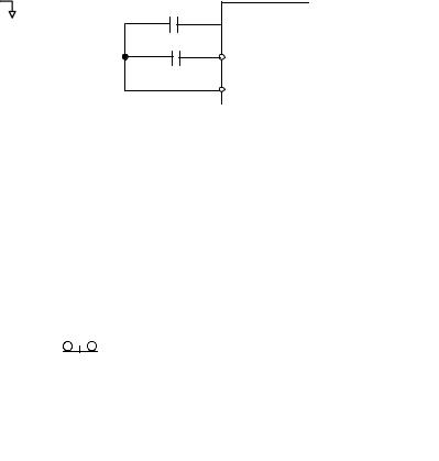
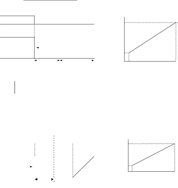
“0:Ramp to stop”: When the Run command is removed, the Drive will decelerate the motor to 0 rpm. The rate of deceleration is determined by the active deceleration time. The factory default Decel Time is parameter C1-02.
When the output frequency has dropped below the DC Injection Start Frequency in b2-01 (Default = 0.5HZ) DC current will be injected in the motor at a level determined by b2-02 (50% Default). The DC Injection condition will occur for the time specified by b2-04 (0.0 Default), to establish the end point of the ramp. DC injection can be used to insure the motor is at zero rpm prior to the Drive shutting off.
ON (CLOSED)
Run Command
OFF (OPEN)
100 %
Output Frequency |
Deceleration Time (C1-02) |
|
|
|
|
|
|
b2-01 |
|
|
|
|
|
|
|
|
|
||||
|
|
|
|
|
|
|
|
|
||
|
|
|
|
|
|
|
|
|
||
0 % |
|
|
|
DC Injection Brake |
|
|||||
|
TIME |
| |
|
b2-04 |
|
|
|
| |
||
|
|
|
|
|
||||||
|
|
|
|
|
|
|
|
|
|
|
Fig. 4 Deceleration to Stop
The actual deceleration time can be determined by the following formula
Time to Stop = Output Freq. at time of stop command × Setting of active Decel Time (C1 - 02), -04, -06 or -08) Maximum Frequency (E1 - 04)
If S-Curve characteristics are specified by the Drive programming, they will add to the total time to stop.
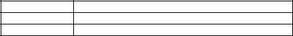
“1:Coast to stop”: When the Run command is removed, the Drive will turn off its output and the motor will coast (uncontrolled deceleration). The friction of the driven equipment will eventually overcome any residual inertia of the system and the rotation will stop.
Programming 8
ON (CLOSED)
Run Command
OFF (OPEN)
100 % |
|
|
Motor Speed |
Output Frequency |
Drive Output Frequency Interrupted |
0 % |
TIME |
|
Fig. 5 Coast to Stop
IMPORTANT |
After a stop is initiated, a subsequent Run commands input before the Minimum Baseblock Time (L2-03) |
|
has expired, will be ignored. |
||
|
||
|
|
Programming 9
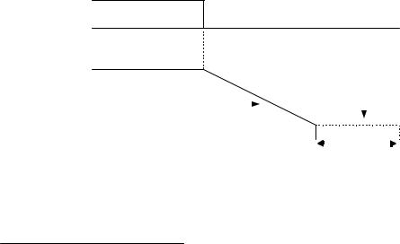
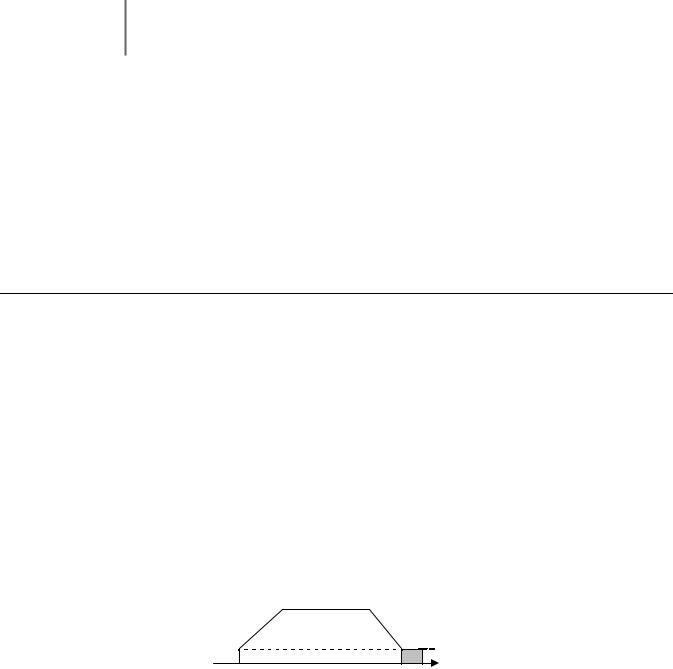
2:DCInj to Stop: When the Run command is removed, the Drive will Baseblock (turn off its output) for the Minimum Baseblock Time (L2-03). Once the Minimum Baseblock Time has expired, the Drive will inject DC current into the motor windings to lock the motor shaft. The stopping time will be reduced as compared to Coast to Stop. The level of DC Injection current is set by parameter b2-02 (50% Default). The DC Injection brake time is determined by the set value in b2-04 and the output frequency at the time the Run command is removed.
DC Injection Brake Time = (b2 - 04) × 10 × Output Frequency
Maximum Frequency (E1 - 04)
Run Command
100 %
Output Frequency
0 %
IMPORTANT
ON
(CLOSED)
b2-04 x 10
OFF
|
|
|
|
|
|
(OPEN) |
|
|
|
|
Drive Output Voltage Interrupted |
|
Injection BrakeTime |
|
|||
|
|
|
DC |
|
||||
|
|
|
|
|
|
|
|
|
|
|
|
|
|
|
|
b2-04 |
|
|
|
|
|
|
DC Injection Brake |
|
|
|
|
|
|
|
|
|
100% (Maximum |
||
Minimum Baseblock |
|
DC Injection Brake Time |
10% |
|||||
|
Time (L2-03) |
|
b2-04 |
Output Frequency) |
||||
Fig. 6 DC Injection Braking to Stop
If an overcurrent (OC) fault occurs during DCInj to Stop, lengthen the Minimum Baseblock Time (L2-03) until the fault no longer occurs.
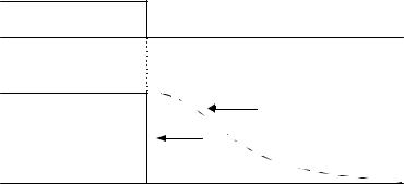
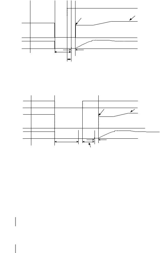
3:Coast w/Timer: When the Run command is removed, the Drive will turn off its output and the motor will coast to a stop. If a Run command is input before time T (value of C1-02) expires, the Drive will not run and the Run command will need to be cycled before operation can occur. The time T (value of C1-02) is determined by the output frequency when the Run command is removed and the active deceleration time.
|
|
|
|
|
|
|
Ignored |
|
|
|||
|
|
|
|
|
|
Run Command |
|
ON |
||||
|
|
|
|
|
|
|
|
|
|
|
|
|
Run Command |
|
|
|
|
|
|
|
|
|
|
(CLOSED) |
|
|
|
|
|
|
|
|
|
|
|
|
|
|
|
|
|
|
|
|
|
|
|
|
|
|
OFF |
|
|
|
|
|
|
|
|
|
|
|
|
|
|
|
|
|
|
|
|
|
|
|
|
|
(OPEN) |
100 % |
|
|
|
|
|
|
|
|
|
|
|
|
Drive Output |
|
|
|
|
|
|
|
|
||||
|
|
|
|
|
|
|
|
|
||||
Output Frequency |
Voltage |
|
|
|
|
|
|
|
|
|
|
|
|
|
|
|
|
|
|
|
|
|
|||
|
Interrupted |
|
|
|
|
|
|
|
|
|||
0 % |
|
|
|
|
|
|
|
|
|
|
|
|
|
|
|
|
|
|
|
|
|
|
|
|
|
|
|
|
|
|
|
|
|
|
||||
|
|
|
|
|
Timer ValueTimerT Value T |
|
|
|||||
|
|
|
|
|
|
(C1-02) (C1-02) |
|
|
|
|||
Operation Wait Time (T)
Deceleration
Time (C1-02)
Minimum
Baseblock
Time (L2-03)
Minimum |
100% (Maximum |
Output |
Output |
Frequency |
Frequency) |
Output Frequency at Stop Command Input
Fig. 7 Coast to Stop with Timer
Programming 10
b1-04 Reverse Operation Selection
Setting |
Description |
0 |
Reverse Enabled (factory default) |
1 |
Reverse Disabled |
2 |
Exchange Phase (N/A if A1-02 = 1 or 3) |
For some applications reverse motor rotation is not applicable and may even cause problems (e.g., air handling units,
pumps, etc.). Setting parameter b1-04 to 1 will cause the Drive to ignore any inputs for reverse operation. Setting parameter b1-04 to 2 will change the motor shaft rotation when a Forward Run command is given by exchanging the order of the output phasing.
The factory default setting of parameter b1-04 is “0: Reverse Enabled”. When b1-04= “1: Disabled”, reverse operation is prohibited and no exchanging of output phasing occurs.
b1-05 Minimum Output Frequency (E1-09) or Less Operation Selection
Setting |
Description |
0 |
Operates According to Frequency Reference (factory default) |
1 |
Output Shuts Off |
2 |
Operates According to E1-09 |
3 |
Zero Speed |
During flux vector control (A1-02 = 3), select an operation mode to be employed when the frequency reference (analog input) drops below the minimum output frequency (El -09). During V/f or open loop vector control, Drive output to the motor is shut off (baseblock) when the output frequency drops below the minimum output frequency (El -09).
b1-06 Digital Input Scan Time
Setting |
Description |
02ms - For 2 Scans
15ms - For 2 Scans (factory default)
This parameter selects the microprocessor scan time for reading multi-function digital inputs (terminals S1 to S8). Set this parameter to “0: 2ms” for quick response and “1: 5ms” for noisy environments.
b1-07 Local/Remote Run Selection
Setting |
Description |
0 |
Cycle Extern Run (factory default) |
1 |
Accept Extrn Run |
When the Drive is switched between the Local mode (the digital operator) to the Remote mode (determined by b1-01 and b1-02), there is the possibility that a Run command is already present (i.e. a switch closure between S1 and SN when b1-02= “1: Terminals”). Parameter b1-07 determines whether the Drive will:
Programming 11
Ignore the external Run command until it is removed and re-instated (b1-07= “0: Cycle Extern Run”)
OR
Accept the already present Run command and immediately begin acceleration to the commanded speed (b1-07= “1: Accept Extrn Run”).
When switching from local mode to remote mode when b1-07=1 the Drive may start unexpectedly if the IMPORTANT Run command is already applied. Be sure all personnel are clear of rotating machinery and electrical
connections prior to switching between local mode and Auto mode.
b1-08 Run Command Selection During Programming
Setting |
Description |
0 |
Disabled (factory default) |
1 |
Enabled |
As a safety precaution, the Drive will not normally respond to a Run input when the digital operator is being used to adjust parameters. If it is necessary that external Run commands be recognized even while the Drive is being programmed, set b1-08= “1: Enabled”.
b2 DC Braking
The DC Braking Group contains parameters associated with the DC injection braking feature. Parameters involving the starting frequency, current level, braking time, and motor pre-heat current level are located here.
b2-01 DC Injection Braking Start Frequency
Setting Range: 0.0 to 10.0 Hz
Factory Default: 0.5 Hz
Parameter b2-01 sets the output frequency where the Drive begins DC Injection during ramp to stop in order to lock the rotor of the motor and established the end point of the ramp. If b2-01 < E1-09 (Minimum Frequency), then DC Injection begins at E1-09.
Parameter b2-01 also determines the output frequency that the Drive must be at or below before a Zero Speed condition is considered true. This affects any digital output configured as a Zero Speed signal (H2-0x= “1: Zero Speed”).
DC injection

|
|
|
b2-01 |
Output Frequency |
| |
| |
time |
|
|||
|
b2-04 |
|
|
Fig. 8 DC Injection Braking During stopping
Programming 12
b2-02 DC Injection Braking Current
Setting Range: 0 to 100%
Factory Default: 50%
The level of DC Injection Braking Current affects the strength of the magnetic field attempting to lock the motor shaft. Increasing the level of current will increase the amount of heat generated by the motor windings and should only be increased to the level necessary to hold the motor shaft. DC Injection current is set in percentage of Drive rated output current. Drive rated output current is stated on the Drive nameplate.
b2-03 DC Injection Braking Time at Start
b2-04 DC Injection Braking Time at Stop
Setting Range: 0.00 to 10.00 Seconds
Factory Default: 0.00 Seconds
The Drive can be programmed to automatically DC Inject for a predetermined amount of time prior to accelerating to speed (b2-03) and/or at the end of a Ramp to stop (b2-04). Parameter b2-03 can be used to stop a rotating motor prior to attempting acceleration (i.e. a wind milling fan). If DC Injection braking at start or Speed Search is not enabled, attempting to drive a spinning motor may cause nuisance tripping.
Parameter b2-04 can be used to resist any residual motion of the load after the deceleration has finished.
DC injection
Output Frequency
|
|
|
|
|
|
|
|
b2-03 |
b2-04 |
||||||
Fig. 9 DC Injection Braking During Starting and stopping
Parameter b2-04 also serves the function of affecting the length of time DC Injection to stop (b1-03= “2: DC Injection to Stop”) will occur.
b2-08 Magnetic Flux Compensation Capacity
Setting Range: 0 to 1000%
Factory Default: 0%
This parameter allows the magnetizing motor flux to be boosted when starting the motor. This parameter will facilitate a quick ramp-up of the torque reference and magnetizing current reference to reduce motor slip during start. A setting of 100% equals motor no-load current E2-03. This flux level will be applied below Minimum Output Frequency (E1-09) until the DC Injection Time at Start (b2-03) expires. This parameter is useful when starting motors that are relatively larger than the Drive, due to the requirement for increased magnetizing current. This parameter may also compensate for reduced starting torque due to motor circuit inefficiencies.
Programming 13

b3 Speed Search
The Speed Search function allows the Drive to determine the speed of a motor shaft that is being driven by rotational inertia. Speed Search will allow the Drive to determine the speed of the already rotating motor and begin to ramp the motor to a set speed without first having to bring it to a complete stop. When a momentary loss of supply power is experienced, the Drive output is turned off. This results in a coasting motor. When power returns, the Drive can determine the speed of the coasting motor and start without requiring it to be brought to minimum speed. Speed Search can be programmed to always be active by setting b3-01 or it can be commanded by remote contact closure by setting a digital input.
There are two forms of Speed Search in the Drive, the speed estimation method and the current detection method.
When setting the Drive for remote Speed Search input, via a contact closure, the method of Speed Search
is determined by the setting of b3-01. If b3-01= ”0: SpdsrchF Disable” then the remote input will initiate IMPORTANT speed estimation method, and if b3-01= ”2: SpdsrchI Disable”, then the remote input will start the current
detection method.
Parameters L2-03 and L2-04 also affect the current detection method of Speed Search operation.
b3-01 Speed Search Selection
Setting |
Description |
0 |
Speed Estimation Speed Search Disable |
1 |
Speed Estimation Speed Search Enable |
2 |
Current Detection Speed Search Disable (factory default) |
3 |
Current Detection Speed Search Enable |
Speed Estimation: Method (b3-01= 0 or 1) The speed estimation method will calculate the speed using measurements of residual motor fields. The speed estimation version is bi-directional and will determine both the motor speed and direction. To enable speed estimation Speed Search at start, set b3-01= “1: SpdsrchF Enable”.
.
IMPORTANT
IMPORTANT
If the speed estimation method of Speed Search is to be used, then Auto-tuning must be performed prior to using Speed Search. If the length of cable between the Drive and motor is ever changed after Auto-tuning then Auto-tuning should be performed again.
The speed estimation mode cannot be used when there are multiple motors operated by one Drive or the motor is two or more frames smaller than the standard size motor per the Drive capacity.
Programming 14
|
|
|
|
AC power supply |
ON |
OFF |
|
|
|
|
|
Output frequency
Output current
Minimum baseblock time (L2-03) x 0.75 *1
*2
Minimum baseblock time (L2-03) x 0.75*1
Start using |
Set frequency |
|
reference |
||
speed detected |
||
|
10 ms
*1 Baseblock time may be reduced by the output frequency
immediately before the baseblock.
*2 After AC power supply recovery, themotormotorwaitswaitsfor thefor the minimum Speed Search Wait Time (b3-05).
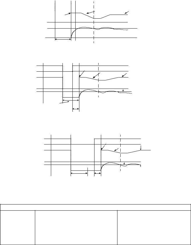
Fig. 10 Speed Search (Estimated Speed Method) after momentary power loss where the power loss time is less than the minimum baseblock time
AC power supply |
ON |
OFF |
Start using speed detected |
|
|
|
|
|
|
|
Set frequency |
Output frequency |
|
|
reference |
|
|
|
|
Output current |
|
|
|
|
|
|
10 ms |
|
Minimum baseblock time |
Speed Search Wait Time |
|
|
(L2-03) |
|
(b3-05) |
Note: If the frequency immediately before the baseblock is low or the power supply off time is long,
Note: If the frequency immediately before the baseblock is low or the power supply break time is long, operation may be the same as the search in case 1.
operation may be the same as the search in case 1.
Fig. 11 Speed Search (Estimated Speed Method) after momentary power loss where the power loss time exceeds the minimum baseblock time
Current Detection Method (b3-01=2 or 3): The current detection method starts searching from a predetermined frequency while monitoring the Drive output current to determine when the rotor speed and the Drive output speed (frequency) match. The current detection version is not bi-directional. To enable current detection Speed Search at start set b3-01= “3: SpdscrhI enable” and program any digital input equal to Speed Search 1 (H1-0x= 61) or Speed Search 2 (H1-0x= 62). Speed Search 1 will start searching from the max. frequency (E1-04) and ramp down to meet the rotor speed. Speed Search 2 will start searching from the set frequency and ramp down to meet the rotor speed.
IMPORTANT If a UV1 fault occurs when current detection Speed Search is attempted, increase the setting of L2-04
IMPORTANT If an OC fault occurs when Speed Search is attempted after power loss recovery, increase the setting of L2-03.
Programming 15
Run command |
OFF |
ON |
Deceleration time set in b3-03 |
|
|
Maximum output |
Set frequency |
frequency or |
reference |
set frequency |
|
Output frequency |
|
b3-02 Speed search current level
Output current |
|
|
* Lower limit is set using Speed SearchTimeDelay(b3Time-05). (b3-05). |
|
|
|
* |
||
|
Minimum baseblock time |
|
|
|
|
(L2-03) |
|
|
|
|
Fig. 12 |
Speed Search (Current Detection Method) at Startup |
||
AC power supply |
ON |
OFF |
Output frequency before power loss Set frequency |
|
|
||||
|
|
|
Deceleration |
reference |
|
|
|
time set in b3-03 |
|
Output frequency |
|
|
|
|
|
|
|
|
|
|
|
|
b3-02 |
|
|
|
|
speed search operating current |
|
Output current |
|
|
*1 Baseblock time may be reduced by the output frequency |
|
|
|
|
||
|
|
|
immediately before baseblock. |
|
Minimum baseblock time (L2-03) *1 |
*2 After AC power supply recovery, motor waits for the minimum |
|||
|
|
|
Speed Search Wait Time (b2b3--0503). |
|
|
|
*2 |
|
|
Fig. 13 Speed Search (Current Detection Method) -
after momentary power loss where the power loss time is less than the minimum baseblock time
AC power supply |
ON |
OFF |
Output frequency before power loss |
Set frequency |
|
|
|
Deceleration time set in b3-03 |
|
|
|
|
reference |
|
|
|
|
speed in b3-03 |
|
Output frequency |
|
|
|
|
|
|
|
b3-02 |
|
|
|
|
Speed search operating time |
|
Output current |
|
|
|
|
|
|
|
Speed search wait time (b3-05) |
|
Minimum baseblock time (L2-03)
Fig. 14 Speed Search (Current Detection Method) -
after momentary power loss where the power loss time exceeds the minimum baseblock time
Speed Search Settings and Methods
Setting of b3-01 |
Automatic Speed Search at RUN command |
Speed Search Method Used for |
Multi-function inputs, momentary power loss, |
||
|
|
baseblock, fault retry |
0 |
No |
Yes - Speed Estimation |
1 |
Yes - Speed Estimation |
Yes - Speed Estimation |
2 |
No |
Yes - Current Detection |
3 |
Yes - Current Detection |
Yes - Current Detection |
Note: When parameter A1-02 = 0 (V/f control without PG) or 2 (open loop vector) the factory default setting is 2. When parameter A1-02 = 1 (V/f control with PG) the factory default setting is 3.
Programming 16
b3-02 Speed Search Deactivation Current
Setting Range: 0 to 200% of Drive rated output current
Factory Default: 120% of Drive rated output current
When using the current detection method of Speed Search (b3-01 = 2 or 3), parameter b3-02 sets the current level that will determine when the search is complete and the rotor and output speeds match. When the output frequency is higher than the actual rotor speed the slip causes the current to be high. As the output frequency is lowered, the closer it comes to the rotor speed, the lower the current draw will be. When the output current drops below the level as set in b3-02 (100% = Drive Rated Current) the output frequency stops decreasing and normal operation resumes.
Note: When parameter A1-02 = 0 (V/f control without PG) the factory default setting is 120. When parameter A1-02 = 2 (Open Loop Vector) the factory default setting is 100.
b3-03 Speed Search Deceleration Time
Setting Range: 0.1 to 10.0 Seconds
Factory Default: 2.0 Seconds
Parameter b3-03 sets the deceleration ramp used by the current detection method of Speed Search (b3-01 = 2 or 3) when searching for the motor’s rotor speed. Even if Speed Search 2 is selected, for Speed Search at start, the time entered into b3-03 will be the time to decelerate from maximum frequency (E1-04) to minimum frequency (E1-09).
b3-05 Speed Search Delay Time
Setting Range: 0.0 to 20.0 Seconds
Factory Default: 0.2 Seconds
In cases where an output contactor is used between the Drive and the motor, extra waiting time is provided after power returns and before Speed Search is performed. This extra time allows for the contactor to operate. When Speed Search at start is used, b3-05 will serve as the lower limit of the Minimum Baseblock Time (L2-03).
b3-10 Speed Search Detection Compensation Gain
Setting Range: 1.00 to 1.20
Factory Default: 1.10
This parameter sets the gain for the frequency reference at which the Drive starts speed estimation speed search. It is used only when b3-01 = 0 or 1.
b3-14 Bi-Directional Speed Search Selection
Setting |
Description |
0 |
Disabled |
1 |
Enabled (factory default) |
The b3-14 parameter can be used to turn off the bi-directional capabilities of the Speed Estimation form of Speed Search. By turning off the bi-directional capability, the speed search will only try to match the speed in the last known direction.
Programming 17

b4 Delay Timers
The Drive has an internal timer function that operates independently from the Drive. A digital input must be programmed to be a timer start input by setting H1-0x= 18. A digital output must be programmed as a timer output by setting H2-0x= 12. (Not to be confused with the “Wait to Run Time” in b1-11)
b4-01 Timer Function ON-Delay Time
Setting Range: 0.0 to 3000.0 Seconds
Factory Default: 0.0 Seconds
The timer start input (H1-0x= 18) must be held on for at least the time specified in parameter b4-01 before the digital output programmed as the timer output will close. See Figure below for timing details.
b4-02 Timer Function OFF-Delay Time
Setting Range: 0.0 to 3000.0 Seconds
Factory Default: 0.0 Seconds
The timer start input (H1-0x= 18) must be held off for at least the time specified by b4-02 before the digital output programmed as the timer output will open. See Figure below for timing details.
Multi-function Contact |
|
|
|
|
|
|
|
|
|
|
|
|
|
|
|
|
|
|
|
|
|
|
|
|
|
|
|
|
|
|
|
|
|
ON (CLOSED) |
|||||||
Input: Timer Function |
|
|
|
|
|
|
|
|
|
|
|
|
|
|
|
|
|
|
|
|
|
|
|
|
|
|
|
|
|
|
|
|
|
|
|
|
|
||||
|
|
|
|
|
|
|
|
|
|
|
|
|
|
|
|
|
|
|
|
|
|
|
|
|
|
|
|
|
|
|
|
|
|
|
|
OFF (OPEN) |
|||||
|
|
|
|
|
|
|
|
|
|
|
|
|
|
|
|
|
|
|
|
|
|
|
|
|
|
|
|
|
|
|
|
|
|
|
|
|
|
|
|
|
|
|
|
|
|
|
|
|
|
|
|
|
|
|
|
|
|
|
|
|
|
|
|
|
|
|
|
|
|
|
|
|
|
|
|
|
|
|
|
|
|
|
|
|
|
|
|
|
|
|
|
|
|
|
|
|
|
|
|
|
|
|
|
|
|
|
|
|
|
|
|
|
|
|
|
|
|
|
|
|
|
|
|
|
ON (CLOSED |
|
|
|
|
|
|
|
|
|
|
|
|
|
|
|
|
|
|
|
|
|
|
|
|
|
|
|
|
|
|
|
|
|
|
|
|
|
|
|
|
|
|
|
|
|
|
|
|
|
|
|
|
|
|
|
|
|
|
|
|
|
|
|
|
|
|
|
|
|
|
|
|
|
|
|
|
|
|
|
|
|
|
|
OFF (OPEN) |
Multi-function Contact |
|
|
|
|
|
|
|
|
|
|
|
|
|
|
|
|
|
|
|
|
|
|
|
|
|
|
|
|
|
|
|
|
|
||||||||
|
|
|
|
|
|
|
|
|
|
|
|
|
|
|
|
|
|
|
|
|
|
|
|
|
|
|
|
|
|
|
|
|
|||||||||
|
|
|
|
|
|
|
|
|
|
|
|
|
|
|
|
|
|
|
|
|
|
|
|
|
|
|
|
|
|
|
|
|
|
||||||||
Output: Timer Function |
|
|
|
|
|
|
|
|
|
|
|
|
|
|
|
|
|
|
|
|
|
|
|
|
|
|
|
|
|
|
|
|
|
|
|||||||
|
|
|
|
|
|
|
|
|
|
|
|
|
|
|
|
|
|
|
|
|
|
|
|
|
|
|
|
|
|
|
|
|
|
||||||||
|
|
|
|
B4-01 |
B4-02 |
|
|
|
|
|
|
|
|
|
|
B4-01 |
|
|
|
|
|
|
|
B4-02 |
|||||||||||||||||
|
|
|
|
|
|
|
Fig. 15 |
Timing Diagram of Timer Function |
|
|
|
|
|
|
|
|
|
|
|
|
|
|
|
||||||||||||||||||
b5 PID Function
The capability to accept an analog signal as feedback for a PID (Proportional + Integral + Derivative) control function is built into the Drive. The PID control function provides closed-loop control and regulation of a system variable such as temperature or pressure. A control signal based on the difference (or proportion) between a feedback signal and a desired setpoint is produced. Integration and derivative calculations are then performed on this signal, based upon the PID parameter settings (B5-01 to B5-19), to minimize deviation, for more precise control.
Proportional - P
PID refers to the type of action used to control modulating equipment such as valves or dampers. With proportional control, a control signal based on the difference between an actual condition and a desired condition is produced. The difference, such as that between an actual temperature and setpoint is the “error”. The inverter adjusts its output signal related directly to the error magnitude.
Integral - I
The integral action is designed to minimize offset. An integrating term is used to observe how long the error condition has existed, summing the error over time. Once the system has stabilized, the offset would be minimized.
Programming 18
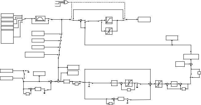
Derivative - D
Overshoot refers to a control loop tendency to overcompensate for an error condition, causing a new error in the opposite direction. Derivative action provides an anticipatory function that exerts a “braking” action on the control loop. When combined, the proportional integral, and derivative actions provide quick response to error, close adherence to the setpoint, and control stability.
The analog feedback to the Drive for the PID control is via the A2 or A3 terminal. Set parameter H3-09 or H3-05 to “B: PID Feedback” to use terminal A2 or A3, respectively, as feedback for the PID functionality of the Drive. To use the analog input terminal A2 or A3 as the PID setpoint, set parameter H3-09 or H3-05 to “C: PID Setpoint,” respectively. The PID setpoint can be configured to come from one of many different inputs or parameters. The table below describes the options for originating the PID setpoint.
|
|
|
B5-01 = 0 |
|
|
|
|
|
|
|
|
FWD or REV Jog multi-function input closed |
|
|
|
|
|
|
|
|
|
PID Disable multi-function input closed |
|
|
|
|
|
|
|
Frequency Reference |
|
|
|
|
|
|
|
|
|
|
B1-01 = 4 |
B5-17 |
|
|
|
|
|
|
|
Pulse Input |
PID Accel/Decel Time |
|
|
|
|
|
Fmax x 110% |
|
|
|
3 |
|
|
True |
|
|
|
|
|
|
2 |
|
|
|
B5-01 = 3,4 |
B5-11 = 0 |
True |
Frequency |
|
Option Card |
|
|
|
+ |
|||||
1 |
|
|
|
|
|||||
|
|
|
|
|
|
Reference |
|||
|
0 |
|
PID SFS |
|
|
|
|
|
|
|
|
False |
+ |
|
B5-11 = 1 |
False |
|
||
Communication |
|
|
B5-01 = |
|
|||||
|
|
Cancel multi- |
|
|
|
|
|||
|
|
|
|
|
|
|
|||
|
|
|
function input |
|
|
1,2 |
|
Fmax x 110% |
|
Terminal A1/A2 |
|
PID Setpoint |
closed |
|
|
|
|
|
|
|
|
|
|
|
|
|
|||
|
|
|
|
|
|
|
|
||
|
|
|
|
|
|
|
|
|
|
D1-01 |
|
B5-19 |
|
|
|
|
|
|
|
D1-02 |
|
|
|
|
|
|
|
|
|
|
PID Setpoint |
|
|
|
|
|
|
|
|
D1-03 |
|
B5-18 = 1 |
|
|
|
|
-Fmax x 110% |
|
|
|
|
|
|
|
|
|
|||
. |
|
|
|
|
|
|
U1-37 |
||
|
|
|
|
|
|
|
|
||
. |
|
|
|
|
|
|
|
|
PID Output |
. |
|
Terminal A2/A3 |
|
|
|
|
|
|
|
D1-17 |
|
|
H3-05/H3-09 = C |
|
|
|
|
|
|
Pulse Input
H6-02 = 2
Memobus Register 0006H
PID Setpoint Memobus register 000FH bit 1 = 1
PID Feedback
Pulse Input
H6-02 = 1 U1-24
PID Feedback
Terminal A2/A3 |
+ |
|
+ |
|
H3-05/H3-09 |
- |
|||
|
||||
= B |
|
+ |
|
|
|
|
|
||
|
PID D Time |
|
|
|
+ |
B5-01 = 2,4 |
|
|
|
|
B5-05 |
|
|
|
|
- |
|
|
|
|
B5-01 = |
|
|
|
z-1 |
1,3 |
|
|
|
|
|
|
|
|
|
|
B5-10 |
|
|
|
|
|
|
|
|
PID Output Gain |
|
|
|
|
|
|
|
B5-07 |
+ |
|
|
|
|
|
|
|
PID Offset |
|
U1-38 |
|
|
|
|
|
|
|
+ |
PID Setpoint |
|
|
|
|
|
|
|
|
U1-36 |
|
|
|
|
|
|
|
-1 |
PID Input |
|
|
|
|
|
|
|
|
|
|
|
|
|
|
|
|
|
|
|
|
B5-04 |
|
Upper Limit: |
|
|
B5-09 = 0 B5-09 = 1 |
|
|
|
|
B5-06 |
|
|
|
|
PID P Gain |
|
|
PID I Limit |
|
PID Delay |
|
||
PID I Time |
|
PID Limit |
|
|||||
|
|
|
Time |
|
||||
B5-02 |
|
+ |
|
|
+ |
|
||
1 |
|
|
|
|
|
|||
|
|
+ |
+ |
1 |
+ |
|
||
-1 |
B5-03 |
|
|
|
||||
+ |
|
|
- |
B5-08 |
+ |
|
||
|
|
|
+ |
|
||||
Input Level |
|
|
|
|
||||
PID Integral |
|
|
PID Integral |
|
|
|
|
|
Select multi- |
|
|
|
|
|
z-1 |
||
|
-1 |
Reset multi- |
|
|
|
|||
function input |
Hold multi- |
|
z |
function input |
|
|
|
|
closed |
function input |
|
|
|
|
|
|
|
|
|
closed |
|
|
|
|
||
|
closed |
|
|
|
|
|
|
|
|
|
|
|
|
|
|
|
|
|
|
PID D Time |
B5-01 = 1,3 |
|
|
|
|
|
|
+ |
B5-05 |
|
|
|
|
|
|
|
|
|
|
|
|
|
||
|
- |
|
|
|
|
|
|
|
|
|
B5-01 = 2,4 |
|
|
|
|
|
|
|
|
|
|
|
|
|
|
|
|
z-1 |
|
|
|
|
|
|
|
Fig. 16 PID Block Diagram
b5-01 PID Function Setting
Setting |
Description |
0 |
Disabled (factory default) |
1 |
D = Feedback |
2 |
D = Feed-Forward |
3 |
Frequency Reference + PID Output (D = Feedback) |
4 |
Frequency Reference +PID Output (D = Feed-Forward) |
The Drive can be used as a stand-alone PID controller. If PID functionality is selected by parameter b5-01, the Drive will adjust its output to cause the feedback from a transmitter to match the PID setpoint (b5-19). To enable PID control, set b5-01 to 1, 2, 3, or 4 according to the application.
Programming 19
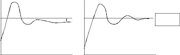
b5-02 Proportional Gain Setting
Setting Range: 0.00 to 25.00
Factory Default: 2.00
The proportional gain will apply a straight multiplier to the calculated difference (error) between the PID Setpoint and the measured transmitter feedback at terminal A2. A large value will tend to reduce the error but may cause instability (oscillations) if too high. A small value may allow to much offset between the setpoint and feedback (See Figure below).
b5-03 Integral Time Setting
Setting Range: 0.0 to 360.0 Seconds
Factory Default: 5.0 Seconds
The Integral factor of PID functionality is a time-based gain that can be used to eliminate the error (difference between the setpoint and feedback at steady state). The smaller the Integral Time set into b5-03, the more aggressive the Integral factor will be. To turn off the Integral Time, set b5-03= 0.00.
Feedback |
|
Measured |
Setpoint |
|
|
|
Offset |
|
Feedback |
|
TIME |
No Intregral
MeasuredFeedback |
Setpoint |
Zero |
|
|
offset with |
|
|
Integral Action |
|
Feedback |
|
|
|
TIME |
With Intregral
Fig. 17 PID Feedback Response Characteristics
b5-04 Integral Limit Setting
Setting Range: 0.0 to 100.0%
Factory Default: 100.0%
On some applications, especially those with rapidly varying loads, the output of the PID function may have large oscillations. To suppress these oscillations, a limit can be applied to the intrigue factor by programming b5-04.
b5-05 Derivative Time Setting
Setting Range: 0.00 to 10.00 Seconds
Factory Default: 100.0%
The derivative calculation attempts to control the remaining overshoot left over after the proportion and integral calculations. If the system is approaching the intended value very rapidly, the derivative control produces a strong braking action to prevent overshoot. If the system is already stable with very little deviation change, derivative control has very little effect. The derivative time is used to dampen oscillations and reduce overshoot, thus improving stability. Setting the derivative time to a larger number produces more braking action in the control system. A setting of 0.00 disables derivative control.
Programming 20
b5-06 PID Output Limit
Setting Range: 0.0 to 100.0%
Factory Default: 100.0%
Places a cap on the output of the PID function. Limiting the PID function may help to prevent large overshoots in the Drive’s response to error (the difference between the setpoint and the feedback).
b5-07 PID Offset Adjustment
Setting Range: -100.0% to +100.0%
Factory Default: 0.0%
The PID Offset Adjustment parameter has two different uses. Parameter b5-07 serves different functions depending on whether it is used on a standard PID loop or a Differential PID loop.
Parameter b5-07 causes an offset to be applied to the output of the PID function in a non-Differential PID loop. Every time the PID output is updated, the offset (b5-07) is summed with the PID output. This can be used to artificially kick-start a slow starting PID loop.
If the Drive is configured for Differential PID Regulation (H3-09= “16: PID Differential”), then this parameter is the targeted setpoint for the maintained differential between the signal measured on analog input A1 and the signal measured on analog input A2.
b5-08 PID Primary Delay Time Constant
Setting Range: 0.00 to 10.00 Seconds
Factory Default: 0.00 Seconds
Acts as a time based filter that lowers the responsiveness of the PID function, but also makes the function more stable when the setpoint varies rapidly or when the feedback is noisy.
b5-09 PID Output Level Selection
Setting |
Description |
0 |
Normal Output (direct acting) (factory default) |
1 |
Reverse Output (reverse acting) |
Normally, the output of the PID function causes an increase in motor speed whenever the measured feedback is below the setpoint. This is referred to as direct acting response. However, if b5-09= “1: Reverse Output”, the output of the PID function causes the motor to slow down when the feedback is below the setpoint. This is referred to as reverse acting response.
b5-10 PID Output Gain Setting
Setting Range: 0.0 to 25.0
Factory Default: 1.0
Applies a multiplier to the output of the PID function. Using the gain can be helpful when the PID function is used to trim the frequency reference. Increasing b5-10 causes the PID function to have a greater regulating affect on the frequency reference.
Programming 21
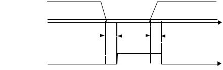
b5-11 PID Reverse Selection
Setting |
Description |
0 |
0 Limit (factory default) |
1 |
Reverse |
Parameter b5-11 determines whether reverse operation is allowed while using PID control (b5-01≠0) and the PID output goes negative. The factory default setting will not allow the Drive to run in reverse when the PID output goes negative. Zero speed limit is automatic when reverse prohibit is selected using b1-04. (Refer also to b5-09).
b5-12 PID Feedback Reference Missing Detection Selection
Setting |
Description |
0 |
Disabled (factory default) |
1 |
Alarm |
3 |
Fault |
b5-13 PID Feedback Loss Detection Level
Setting Range: 0 to 100%
Factory Default: 0%
b5-14 PID Feedback Loss Detection Time
Setting Range: 0.0 to 25.0 Seconds
Factory Default: 1.0 Seconds
Loss of feedback can cause problems to a PID application. The Drive can be programmed to turn on a digital output whenever a loss of feedback occurs. Feedback Loss Detection is turned on by b5-12. When b5-12= “1: Alarm”, the Drive acknowledges the loss of feedback without stopping or turning on the fault output (MA-MB). If b5-12= “2: Fault”, the Drive coasts to a stop and turns on the fault output if the feedback is determined to be lost. The Drive interprets feedback loss whenever the feedback signal drops below the value of b5-13 and stays below that level for at least the time set into b5-14. See Figure below for timing details.
Measured
Feedback
b5-13
|
|
|
T |
|
|
|
|
T |
|
|
|
|
|
|
|
|
|
|
|
|
|
|
|
|
T = b5-14 |
|
|||
|
|
|
|
|
|
|
|
|
||||||
|
|
|
|
|
|
|
|
|
|
|
|
|
||
|
|
|
|
|
|
|
|
|
|
|
|
|
|
|
|
|
|
|
|
|
|
|
|
|
|
|
|
ON (CLOSED) |
|
Feedback |
|
|
|
|
|
|
|
|
|
|
|
|
||
Feedback |
|
|
|
|
|
|
|
|
|
|
|
|
tOFF (OPEN) |
|
Loss Output |
|
|
|
|
|
|
|
|
|
TIME |
|
|||
Loss Digital Output |
|
|
|
|
|
|
|
|
|
|||||
Fig. 18 Loss of PID Feedback Feature
b5-15 Sleep Function Start Level
Setting Range: 0.0 to 200.0 Hz
Factory Default: 0.0 Hz
Programming 22
Loading...