


 Loading...
E7B Drive/Bypass
Technical Manual
|
|
|
|
|
|
|
|
|
|
|
|
|
|
|
|
|
|
|
|
|
|
|
|
|
|
Model: E7B |
Document Number: TM.E7B.01 |
||||
|
|
|
|
|
|
|
|
Quick Reference for Bypass Parameters
Parameter |
Factory |
User |
Parameter |
Factory |
User |
Parameter |
Factory |
User |
Parameter |
Factory |
User |
|
Number |
Setting |
Setting |
Number |
Setting |
Setting |
Number |
Setting |
Setting |
Number |
Setting |
Setting |
|
A1-00 |
0 |
|
b5-04 |
100 |
|
E1-05 |
240V or 480V |
|
|
L1-05 |
0.2 |
|
A1-01 |
2 |
|
b5-06 |
100 |
|
E1-06 |
60 |
|
|
L2-01 |
2 |
|
A1-03 |
0 |
|
b5-07 |
0 |
|
E1-07 |
3 |
|
|
L2-02 |
0.1 |
|
A1-04 |
0 |
|
b5-08 |
0 |
|
E1-08 |
18 |
|
|
L2-03 |
0.1 |
|
A1-05 |
0 |
|
b5-09 |
0 |
|
E1-09 |
1.5 |
|
|
L2-04 |
0.3 |
|
|
|
|
|
|
|
|
|
|
|
|
|
|
A2-01 |
|
|
b5-10 |
1 |
|
E1-10 |
10.8 |
|
|
L2-05 |
190 |
|
|
|
|
|
|
|
|
|
|
|
|
|
|
A2-02 |
|
|
b5-11 |
0 |
|
E1-11 |
0 |
|
|
L3-01 |
1 |
|
|
|
|
|
|
|
|
|
|
|
|
|
|
A2-03 |
|
|
b5-12 |
0 |
|
E1-12 |
0 |
|
|
L3-02 |
120 |
|
|
|
|
|
|
|
|
|
|
|
|
|
|
A2-04 |
|
|
b5-13 |
0 |
|
E1-13 |
0 |
|
|
L3-04 |
1 |
|
|
|
|
|
|
|
|
|
|
|
|
|
|
A2-05 |
|
|
b5-14 |
1 |
|
E2-01 |
kVA Dep. |
|
|
L3-05 |
1 |
|
|
|
|
|
|
|
|
|
|
|
|
|
|
A2-06 |
|
|
b5-15 |
0 |
|
E2-03 |
kVA Dep. |
|
|
L3-06 |
120 |
|
|
|
|
|
|
|
|
|
|
|
|
|
|
A2-07 |
|
|
b5-16 |
0 |
|
E2-05 |
kVA Dep. |
|
|
L4-01 |
0 |
|
A2-08 |
|
|
b5-17 |
0 |
|
F6-01 |
3 |
|
|
L4-02 |
2 |
|
A2-09 |
|
|
b5-18 |
0 |
|
F6-02 |
0 |
|
|
L4-05 |
0 |
|
A2-10 |
|
|
b5-19 |
0 |
|
F6-03 |
1 |
|
|
L4-06 |
80 |
|
A2-11 |
|
|
b5-20 |
1 |
|
F6-05 |
0 |
|
|
L5-01 |
10 |
|
A2-12 |
|
|
b5-21 |
1 |
|
H1-01 |
70 |
|
|
L5-02 |
0 |
|
A2-13 |
|
|
b5-22 |
0 |
|
H1-02 |
|
|
|
L5-03 |
600 |
|
A2-14 |
|
|
b5-23 |
0 |
|
H1-03 |
See Table 2 of |
|
|
L6-01 |
6 |
|
|
|
|
the bypass |
|
|
|
||||||
|
|
|
|
|
|
|
|
|
|
|
|
|
A2-15 |
|
|
b5-24 |
0 |
|
|
|
|
L6-02 |
15 |
|
|
|
|
|
|
schematic |
|
|
|
|||||
|
|
|
|
|
|
|
|
|
|
|
|
|
A2-16 |
|
|
b5-25 |
0 |
|
|
|
|
L6-03 |
10 |
|
|
|
|
|
|
|
|
|
|
|||||
|
|
|
|
|
|
|
|
|
|
|
|
|
A2-17 |
|
|
b5-26 |
0 |
|
H1-04 |
4 |
|
|
L8-01 |
0 |
|
|
|
|
|
|
|
|
|
|
|
|
|
|
A2-18 |
|
|
b5-27 |
60 |
|
H1-05 |
6 |
|
|
L8-02 |
95 |
|
|
|
|
|
|
|
|
|
|
|
|
|
|
A2-19 |
|
|
b5-28 |
0 |
|
H2-01 |
0 |
|
|
L8-03 |
4 |
|
|
|
|
|
|
|
|
|
|
|
|
|
|
A2-20 |
|
|
b5-29 |
1 |
|
H2-02 |
3B |
|
|
L8-06 |
kVA Dep. |
|
|
|
|
|
|
|
|
|
|
|
|
|
|
A2-21 |
|
|
b5-30 |
0 |
|
H3-02 |
See Table 2 of |
|
|
L8-09 |
1 |
|
A2-22 |
|
|
b8-01 |
1 |
|
|
the bypass |
|
|
L8-10 |
0 |
|
|
|
|
|
schematic |
|
|
|
|||||
A2-23 |
|
|
b8-04 |
kVA Dep. |
|
|
|
|
L8-11 |
300 |
|
|
|
|
|
|
|
|
|
|
|||||
A2-24 |
|
|
b8-05 |
20 |
|
H3-03 |
0 |
|
|
L8-12 |
45 |
|
A2-25 |
|
|
b8-06 |
0 |
|
H3-08 |
See Table 2 of |
|
|
L8-15 |
1 |
|
A2-26 |
|
|
C1-01 |
60 |
|
|
the bypass |
|
|
L8-18 |
1 |
|
|
|
|
|
schematic |
|
|
|
|||||
A2-27 |
|
|
C1-02 |
60 |
|
|
|
|
L8-19 |
20 |
|
|
|
|
|
|
|
|
|
|
|||||
A2-28 |
|
|
C1-03 |
30 |
|
H3-09 |
See Table 2 of |
|
|
n1-01 |
1 |
|
A2-29 |
|
|
C1-04 |
30 |
|
|
the bypass |
|
|
n1-02 |
1 |
|
|
|
|
|
schematic |
|
|
|
|||||
A2-30 |
|
|
C1-09 |
10 |
|
|
|
|
n3-01 |
5 |
|
|
|
|
|
|
|
|
|
|
|||||
|
|
|
|
|
|
|
|
|
|
|
|
|
A2-31 |
|
|
C1-11 |
0 |
|
H3-10 |
100 |
|
|
n3-02 |
150 |
|
|
|
|
|
|
|
|
|
|
|
|
|
|
A2-32 |
|
|
C2-01 |
0.2 |
|
H3-11 |
0 |
|
|
n3-03 |
1 |
|
|
|
|
|
|
|
|
|
|
|
|
|
|
b1-01 |
See Table 2 of |
|
C2-02 |
0.2 |
|
H3-12 |
0.3 |
|
|
n3-04 |
40 |
|
|
the bypass |
|
|
|
|
|
|
|
|
|
|
|
|
|
C4-01 |
1 |
|
H3-13 |
See Table 2 of |
|
|
o1-01 |
6 |
|
|
|
schematic |
|
|
|
|
|
||||||
|
|
|
|
|
|
the bypass |
|
|
|
|
|
|
|
|
C4-02 |
200 |
|
|
|
|
o1-02 |
1 |
|
||
|
|
|
|
|
|
|
|
|||||
|
|
|
|
|
schematic |
|
|
|
||||
|
|
|
|
|
|
|
|
|
|
|
|
|
b1-02 |
1 |
|
C6-02 |
kVA Dep. |
|
|
|
|
o1-03 |
0 |
|
|
|
|
|
|
|
|
|
||||||
|
|
|
|
|
|
|
|
|
|
|
|
|
b1-03 |
0 |
|
C6-03 |
kVA Dep. |
|
H4-01 |
2 |
|
|
o1-05 |
3 |
|
b1-04 |
1 |
|
C6-04 |
kVA Dep. |
|
H4-02 |
100 |
|
|
o1-06 |
0 |
|
b1-07 |
1 |
|
C6-05 |
0 |
|
H4-03 |
0 |
|
|
o1-07 |
2 |
|
b1-08 |
1 |
|
d1-01 |
10.0 |
|
H4-04 |
8 |
|
|
o1-08 |
3 |
|
b1-11 |
0 |
|
d1-02 |
6.0 |
|
H4-05 |
50 |
|
|
o2-01 |
1 |
|
b1-12 |
0 |
|
d1-03 |
0 |
|
H4-06 |
0 |
|
|
o2-02 |
0 |
|
b2-01 |
0.5 |
|
d1-04 |
40 |
|
H4-07 |
0 |
|
|
o2-03 |
0 |
|
|
|
|
|
|
|
|
|
|
|
|
|
|
b2-02 |
50 |
|
d1-17 |
6 |
|
H4-08 |
0 |
|
|
o2-04 |
kVA Dep. |
|
|
|
|
|
|
|
|
|
|
|
|
|
|
b2-03 |
5.0 |
|
d2-01 |
100 |
|
H5-01 |
1F |
|
|
o2-05 |
1 |
|
|
|
|
|
|
|
|
|
|
|
|
|
|
b2-04 |
0 |
|
d2-02 |
0 |
|
H5-02 |
3 |
|
|
o2-06 |
1 |
|
|
|
|
|
|
|
|
|
|
|
|
|
|
b2-09 |
0 |
|
d2-03 |
0 |
|
H5-03 |
0 |
|
|
o2-07 |
0 |
|
|
|
|
|
|
|
|
|
|
|
|
|
|
b3-01 |
2 |
|
d3-01 |
0 |
|
H5-04 |
3 |
|
|
o2-08 |
1 |
|
|
|
|
|
|
|
|
|
|
|
|
|
|
b3-02 |
120 |
|
d3-02 |
0 |
|
H5-05 |
1 |
|
|
o2-10 |
0 |
|
|
|
|
|
|
|
|
|
|
|
|
|
|
b3-03 |
2 |
|
d3-03 |
0 |
|
H5-06 |
5 |
|
|
o2-12 |
0 |
|
b3-05 |
0.2 |
|
d3-04 |
1 |
|
H5-07 |
1 |
|
|
o2-14 |
0 |
|
b3-14 |
1 |
|
d4-01 |
0 |
|
H5-08 |
0 |
|
|
o2-15 |
0 |
|
b4-01 |
0 |
|
d4-02 |
10 |
|
H5-09 |
2 |
|
|
o3-01 |
0 |
|
b4-02 |
0 |
|
E1-01 |
208, 240V or |
|
L1-01 |
1 |
|
|
o3-02 |
1 |
|
b5-01 |
0 |
|
|
480V |
|
L1-02 |
8 |
|
|
T1-02 |
kVA Dep. |
|
|
|
|
|
|
|
|
||||||
b5-02 |
2 |
|
E1-03 |
F |
|
L1-03 |
3 |
|
|
T1-04 |
kVA Dep. |
|
b5-03 |
5 |
|
E1-04 |
60 |
|
L1-04 |
1 |
|
|
|
|
|

Warnings and Cautions
This Section provides warnings and cautions pertinent to this product, that if not heeded, may result in personal injury, fatality, or equipment damage. Yaskawa is not responsible for consequences of ignoring these instructions.

 WARNING
YASKAWA manufactures component parts that can be used in a wide variety of industrial applications. The selection and application of YASKAWA products remain the responsibility of the equipment designer or end user. YASKAWA accepts no responsibility for the way its products are incorporated into the final system design. Under no circumstances should any YASKAWA product be incorporated into any product or design as the exclusive or sole safety control. Without exception, all controls should be designed to detect faults dynamically and fail safely under all circumstances. All products designed to incorporate a component part manufactured by YASKAWA must be supplied to the end user with appropriate warnings and instructions as to that part’s safe use and operation. Any warnings provided by YASKAWA must be promptly provided to the end user. YASKAWA offers an express warranty only as to the quality of its products in conforming to standards and specifications published in the YASKAWA manual. NO OTHER WARRANTY, EXPRESS OR IMPLIED, IS OFFERED. YASKAWA assumes no liability for any personal injury, property damage, losses, or claims arising from misapplication of its products.

 WARNING
•Read and understand this manual before installing, operating, or servicing this Drive and Bypass Unit. All warnings, cautions, and instructions must be followed. All activity must be performed by qualified personnel. The Drive must be installed according to this manual and local codes.
•Do not connect or disconnect wiring while the power is on. Do not remove covers or touch circuit boards while the power is on.
•Before servicing, disconnect all power to the equipment. The internal capacitor remains charged even after the power supply is turned off. Status indicator LEDs and Digital Operator display will be extinguished when the DC bus voltage is below 50 VDC. To prevent electric shock, wait at least five minutes after all indicators are OFF and measure DC bus voltage level to confirm safe level.
•Do not perform a withstand voltage test on any part of the unit. This equipment uses sensitive devices and may be damaged by high voltage.
•The Drive and Bypass unit is not suitable for circuits capable of delivering more than the specified RMS symmetrical amperes. Install adequate branch short circuit protection per applicable codes. Refer to the specification. Failure to do so may result in equipment damage and/or personal injury.
•Do not connect unapproved LC or RC interference suppression filters, capacitors, or overvoltage protection devices to the output of the Drive. These devices may generate peak currents that exceed Drive specifications.
•To avoid unnecessary fault displays caused by contactors or output switches placed between Drive and motor, auxiliary contacts must be properly integrated into the control logic circuit.
•YASKAWA is not responsible for any modification of the product made by the user; doing so will void the warranty. This product must not be modified.
•Verify that the rated voltage of the Drive and Bypass unit matches the voltage of the incoming power supply before applying power.
•To meet CE directives, proper line filters and proper installation are required.
i


 WARNING
•Some drawings in this manual may be shown with protective covers or shields removed, to describe details. These must be replaced before operation.
•Observe electrostatic discharge procedures when handling circuit cards to prevent ESD damage.
•The equipment may start unexpectedly upon application of power. Clear all personnel from the Drive, motor, and machine area before applying power. Secure covers, couplings, shaft keys, and machine loads before energizing the Drive and Bypass unit.
•Please do not connect or operate any equipment with visible damage or missing parts. The operating company is responsible for any injuries or equipment damage resulting from failure to heed the warnings in this manual.
Intended Use
Drives and Bypass Units are intended for installation in electrical systems or machinery.
For use in the European Union, the installation in machinery and systems must conform to the following product standards of the Low Voltage Directive:
EN 50178, 1997-10, Equipping of Power Systems with Electronic Devices EN 60201-1, 1997-12 Machine Safety and Equipping with Electrical Devices
Part 1: General Requirements (IEC 60204-1:1997)/
EN 61010, 1997-11Safety Requirements for Information Technology Equipment (IEC 950:1991 + A1:1992 + A2:1993 + A3:1995 + A4:1996, modified)
Other
The Drive and Bypass unit is suitable for use on a circuit capable of delivering not more than 100,000 RMS symmetrical amperes, 240Vac maximum (240V Class) and 480Vac maximum (480V Class).
This manual is for reference only and subject to change without notice.
ii

Introduction
This Section describes the applicability of the Manual
Product Description
The E7 Bypass unit provides a means of bypassing the Drive while allowing the motor to operate at full speed, directly from the AC line. It incorporates an AC Drive and three contactor Bypass arrangement in a single UL listed enclosure. The three electrically interlocked IEC rated contactors isolate the Drive when operating in Bypass mode.
Control logic provides industry standard Hand/Off/Auto functions and safety circuit interlocks in both drive and Bypass operating modes.
E7 Bypass components include: a fused 120 VAC control circuit transformer, an input Motor Circuit Protector (MCP) circuit breaker/disconnect, motor overload relay, selector switches and indicating lights.
The E7 Drive, a component of the E7 Bypass package, is a Pulse Width Modulated Drive for 3-Phase AC induction motors. This type of Drive is also known as an Adjustable Frequency Drive, Variable Frequency Drive, AC Drive, AFD, ASD, VFD, and Inverter. In this manual, the E7 Drive will be referred to as the “Drive”.
The Drive is a variable torque AC drive, designed specifically for HVAC applications in building automation, including fans, blowers and pumps. A new benchmark for size, cost, performance, benefits, and quality, the Drive includes numerous built-in features such as network communications, H/O/A, PI, parameter storage and copy functions.
The Drive has embedded communications for the popular building automation protocols, Johnson Controls Metasys® N2 and Siemens APOGEE™ FLN, as well as Modbus®. An optional LONWORKS® interface card is also available.
The LCD keypad/operator is equipped with Hand/Off/Auto functions, copy feature, 7 language choices, and 5 lines of display with 16 characters per line. User parameter settings can be recovered at any time via “User Initialization”. Optional DriveWizard software allows upload/download, as well as graphing and monitoring of drive parameters from a PC for ease of drive management.
Built-in PI control eliminates the need for closed loop output signals from a building automation system. It includes feedback display, inverse, square root and differential control functions, and maintains setpoint for closed loop control of fans and pumps for pressure, flow, or temperature regulation.
This manual is applicable to E7 Drives defined by model numbers CIMR-E7U_ _ _ _ contained within Bypass units defined by model numbers E7B_ _ _ _. This manual reflects the software version 4010.
This manual is subject to change as product improvements occur. The latest version of the manual can be obtained from the Yaskawa website www.yaskawa.com . The date shown on the rear cover is changed when revisions are made.
Introduction iii

This manual may describe trademarked equipment, which is the property of other companies. These trademarks are the property of the registered owner companies and may include the following:
APOGEETM FLN, trademark of Siemens Building Technologies, Inc.
Metasys®, trademark of Johnson Controls Inc.
Modbus®, trademark of Schneider Automation, Inc.
LONWORKS®, trademark of Echelon Corporation
Other Documents and Manuals are available to support special use or installation of this product. These documents may be provided with the product or upon request or downloaded from www.drives.com. Documents may include the following:
TM.E7.02.Programming … Manual included on CD ROM with product
TM.E7.11.Modbus … Manual included on CD ROM with product
TM.AFD.20.LONWORKS … Manual included on CD ROM with product
TM.E7.21.APOGEE … Manual included on CD ROM with product
TM. E7.22. Metasys … Manual included on CD ROM with product
DriveWizard … Software and Manual…Included on CD ROM with product
Option Instructions … Included on CD ROM with product
Definitions of Acronyms and Abbreviations
AC |
Alternating Current |
LRA |
Locked Rotor Amperes |
AIC |
Amps Interrupting Capacity |
MCP |
Motor Circuit Protector |
CB |
Circuit Breaker |
MTBF |
Mean Time Between Failures |
CIMR |
Control Induction Motor Rotation |
NC |
Normally Closed |
CN |
Connector |
NEC |
National Electrical Code |
CPT |
Control Power Transformer |
NEMA |
National Electrical Manufacturers Association |
CPU |
Central Processing Unit |
NO |
Normally Open |
DIP |
Dual Inline Package |
OLR |
Over Load Relay |
FLA |
Full Load Amperes |
PCB |
Printed Circuit Board |
FVFF |
Forced Ventilated, inlet Filter, outlet Filter |
PI |
Proportional plus Integral control action |
HOA |
Hand/Off/Auto |
RTS |
Request To Send |
HP |
Horsepower |
SFS |
Soft Start |
IEC |
International Electrotechnical Commission |
TB |
Terminal Block |
IGV |
Inlet Guide Vanes |
THD |
Total Harmonic Distortion |
IPM |
Intelligent Power Module |
VA |
Volt Amperes |
KVA |
Kilo Volt Amperes |
VAC |
Volts Alternating Current |
LED |
Light Emitting Diode |
VAV |
Variable Air Volume |
Terminology in This Manual
“Standard” or “Configured” options - are available with standard lead times
“Engineered” or “Custom” options - are available only with extended lead times
Introduction iv

Resources Available
|
|
Table of Resources |
|
|
|
|
Manuals, Installation Guides, and CD’s |
|
|
|
|
Document Number |
|
Description |
|
|
|
TM.E7.01 |
E7 Drive User Manual |
|
|
|
|
TM.E7.02 |
E7 Drive Programming Manual |
|
|
|
|
TM.E7.21 |
E7 APOGEE™ FLN Technical Manual |
|
|
|
|
TM.E7.22 |
E7 |
Metasys® N2 Technical Manual |
|
|
|
IG.AFD.20 |
LONWORKS® Option Installation Guide |
|
|
|
|
IG.AFD.23 |
BACnet Option Installation Guide |
|
|
|
|
IG.AFD.50 |
3-15 PSI Pressure Transducer Installation Guide |
|
|
|
|
IG.E7B.02 |
E7B Drive Bypass System with Touchpad Control Panel Option |
|
|
|
|
CD.E7.01 |
CD ROM, Drives for Building Automation |
|
|
|
|
|
|
Software |
|
|
|
Document |
|
Description |
|
|
|
DriveWizard® Software |
DriveWizard® Software Version 5.3 |
|
|
|
|
ESP |
Energy Savings Predictor for E7 |
|
|
|
|
Flyers, Bulletins, Pricebook, Binders, And Specifications |
||
|
|
|
Document Number |
|
Description |
|
|
|
FL.E7.01 |
Flyer, 2 page, E7 Drives and Bypass Packages |
|
|
|
|
BL.E7.01 |
Bulletin, Multi-page, E7 Drives and Bypass Packages |
|
|
|
|
PB.E7.01 |
E7 |
Price Book |
|
|
|
DRG.E7 |
E7 |
Drives Resources Guide Binder for Building Automation |
|
|
|
SG.E7.01 EngSpec15172 |
E7 |
Specification Guide, Section 15172 for Consulting Engineers |
|
|
|
SG.E7.10 SubmittalSpec |
E7 |
Submittal Specification |
|
|
|
SG.E7B.10 SubmittalSpec |
E7 |
Bypass Submittal Specification |
|
|
|
SG.E7C.10 SubmittalSpec |
E7 |
Configured Submittal Specification |
|
|
|
SG.E7E.10 SubmittalSpec |
E7 |
Engineered Submittal Specification |
|
|
|
See also www.drives.com.
Introduction v
Notes:
Introduction vi

Table of Contents |
|
Quick Reference Parameter List ........................................................ |
Inside front cover |
Warnings and Cautions ................................................................................................ |
i |
Introduction.................................................................................................................. |
iii |
Chapter 1 - Physical Installation ............................................................................... |
1-1 |
Bypass Model Number and Enclosure Style .............................................................. |
2 |
Enclosure Data ........................................................................................................... |
4 |
Confirmations upon Delivery ...................................................................................... |
7 |
Bypass Product Options ............................................................................................. |
9 |
Bypass Component Descriptions ............................................................................. |
11 |
Exterior and Mounting Dimensions .......................................................................... |
17 |
Checking and Controlling Installation Site ................................................................ |
24 |
Chapter 2 - Electrical Installation.............................................................................. |
2-1 |
Termination Configuration - Power Wiring ................................................................. |
2 |
Control Wiring ............................................................................................................. |
9 |
Wiring Diagram ......................................................................................................... |
20 |
Logic Diagram .......................................................................................................... |
22 |
Chapter 3 - Control Panel .......................................................................................... |
3-1 |
Digital Operator and Control Panel Display ............................................................... |
2 |
Drive Main Menus ...................................................................................................... |
8 |
Example of Changing a Parameter .......................................................................... |
16 |
Chapter 4 - Start Up and Operation .......................................................................... |
4-1 |
Start Up Introduction .................................................................................................. |
2 |
Bypass Start Up Preparation....................................................................................... |
3 |
Bypass Unit Start Up Procedure ................................................................................. |
4 |
Bypass Operation Description..................................................................................... |
8 |
Chapter 5 - Programming .......................................................................................... |
5-1 |
Bypass Basic Programming Parameters ................................................................... |
2 |
Table of Contents vii
Chapter 6 - Diagnostics & Troubleshooting ........................................................... |
6-1 |
Bypass Diagnostics .................................................................................................... |
2 |
Drive Diagnostics ....................................................................................................... |
3 |
Drive Troubleshooting .............................................................................................. |
17 |
Drive Main Circuit Test Procedure ............................................................................ |
23 |
Drive Date Stamp Information .................................................................................. |
27 |
Chapter 7 - Maintenance ............................................................................................ |
7-1 |
Maintenance ............................................................................................................... |
2 |
Removing and Replacing Drive in a Bypass Unit ....................................................... |
9 |
Appendix A - Parameters.......................................................................................... |
A-1 |
Parameter List ............................................................................................................ |
2 |
Monitor List ............................................................................................................... |
26 |
Fault Trace List ........................................................................................................ |
28 |
Fault History List ...................................................................................................... |
29 |
Appendix B - Capacity Related Parameters............................................................ |
B-1 |
Drive Capacity ............................................................................................................ |
2 |
Appendix C - Specifications ..................................................................................... |
C-1 |
Standard Drive and Bypass Specifications ................................................................. |
2 |
Appendix D - Communication .................................................................................. |
D-1 |
Using Modbus Communication .................................................................................. |
2 |
Modbus Function Code Details .................................................................................. |
7 |
Modbus Data Tables .................................................................................................. |
9 |
Modbus Self-Diagnosis ............................................................................................ |
14 |
Metasys N2 Point Database...................................................................................... |
15 |
APOGEE FLN Point Database.................................................................................. |
19 |
Appendix E - Peripheral Devices ............................................................................. |
E-1 |
Drive Input Fuse Selection for I2t Protection ............................................................... |
2 |
General Peripheral Devices ....................................................................................... |
4 |
Table of Contents viii
Appendix F - Replacement Parts ............................................................................. |
F-1 |
Bypass Replacement Parts......................................................................................... |
2 |
Index .................................................................................................................... |
Index-1 |
Table of Contents ix
Notes:
Table of Contents x

Chapter 1
Physical Installation
This chapter describes the checks required upon receiving and the installation process for a Drive and Bypass unit.
Bypass Model Number and Enclosure Style .................................. |
2 |
Enclosure Data ............................................................................... |
4 |
Confirmations upon Delivery .......................................................... |
7 |
Receiving Checks ...................................................................... |
7 |
Bypass Nameplate Information .................................................. |
7 |
Bypass Unit Enclosures ............................................................. |
8 |
Bypass Product Options ................................................................. |
9 |
Bypass Component Descriptions ................................................. |
11 |
Bypass Unit Front Control Panel ............................................ |
11 |
Exterior and Mounting Dimensions .............................................. |
17 |
Bypass Unit 30 HP and Below, 480 VAC; |
|
15 HP and Below, 208V/240V ................................................. |
17 |
Bypass Unit 30 HP and Below, 480 VAC; |
|
15 HP and Below, 208V/240V With Add-On Box ................... |
18 |
Bypass Unit 40 HP to 100 HP, 480 VAC; |
|
20 HP to 40 HP, 208V/240V .................................................... |
19 |
Bypass Unit 40 HP to 100 HP, 480 VAC; |
|
20 HP to 40 HP, 208V/240V With Add-On Box ........................ |
20 |
Bypass Unit 125 HP to 250 HP, 480 VAC; |
|
50 HP to 125 HP, 208V ............................................................ |
21 |
Dimensions and Weights ......................................................... |
22 |
Checking and Controlling Installation Site .................................... |
24 |
Installation Site ........................................................................ |
24 |
Controlling the Ambient Temperature ...................................... |
25 |
Protecting the Bypass Unit from Foreign Matter ...................... |
25 |
Installation Orientation and Enclosure Considerations ............ |
26 |
Physical Installation 1 - 1

Bypass Model Number and Enclosure Style
The Bypass covers two voltage ranges: 208-240 VAC and 480 VAC. Ratings applicable are from 1/2 to 500 HP.
|
|
|
Table 1.1 |
Bypass |
|
|
|
|
|
|
|
|
|
|
|
|
|
Bypass |
|
|
Bypass |
|
|
|
Base Model Number |
|
|
Continuous |
Uses |
||
Voltage |
|
|
*NEMA 12 |
|
HP |
Output |
Basic Drive |
|
NEMA 1 |
|
|
|
Current |
Model-Number |
|
|
|
FVFF |
|
|
|||
|
|
|
|
|
(Amps) |
|
|
|
|
|
|
|
|
|
|
|
E7BVD002 |
|
E7BBD002 |
|
0.5 |
2.4 |
CIMR-E7U22P2 |
|
|
|
|
|
|
|
|
|
E7BVD003 |
|
E7BBD003 |
|
0.75 |
3.5 |
CIMR-E7U22P2 |
|
|
|
|
|
|
|
|
|
E7BVD004 |
|
E7BBD004 |
|
1 |
4.6 |
CIMR-E7U22P2 |
|
|
|
|
|
|
|
|
|
E7BVD007 |
|
E7BBD007 |
|
2 |
7.5 |
CIMR-E7U22P2 |
|
|
|
|
|
|
|
|
|
E7BVD010 |
|
E7BBD010 |
|
3 |
10.6 |
CIMR-E7U22P2 |
|
|
|
|
|
|
|
|
|
E7BVD016 |
|
E7BBD016 |
|
5 |
16.7 |
CIMR-E7U23P7 |
|
|
|
|
|
|
|
|
|
E7BVD024 |
|
E7BBD024 |
|
7.5 |
24.2 |
CIMR-E7U27P5 |
|
|
|
|
|
|
|
|
|
E7BVD030 |
|
E7BBD030 |
|
10 |
30.8 |
CIMR-E7U27P5 |
|
|
|
|
|
|
|
|
|
E7BVD046 |
|
E7BBD046 |
|
15 |
46.2 |
CIMR-E7U2011 |
|
|
|
|
|
|
|
|
208 VAC |
E7BVD059 |
|
E7BBD059 |
|
20 |
59.4 |
CIMR-E7U2015 |
|
|
|
|
|
|
|
|
|
E7BVD074 |
|
E7BBD074 |
|
25 |
74.8 |
CIMR-E7U2018 |
|
|
|
|
|
|
|
|
|
E7BVD088 |
|
E7BBD088 |
|
30 |
88 |
CIMR-E7U2022 |
|
|
|
|
|
|
|
|
|
E7BVD114 |
|
E7BBD114 |
|
40 |
114 |
CIMR-E7U2030 |
|
|
|
|
|
|
|
|
|
E7BVD143 |
|
E7BBD143 |
|
50 |
143 |
CIMR-E7U2037 |
|
|
|
|
|
|
|
|
|
E7BVD169 |
|
E7BBD169 |
|
60 |
169 |
CIMR-E7U2045 |
|
|
|
|
|
|
|
|
|
E7BVD211 |
|
E7BBD211 |
|
75 |
211 |
CIMR-E7U2055 |
|
|
|
|
|
|
|
|
|
E7BVD273 |
|
E7BBD273 |
|
100 |
273 |
CIMR-E7U2075 |
|
|
|
|
|
|
|
|
|
E7BVD343 |
|
E7BBD343 |
|
125 |
343 |
CIMR-E7U2090 |
|
|
|
|
|
|
|
|
|
E7BVD396 |
|
E7BBD396 |
|
150 |
396 |
CIMR-E7U2110 |
|
|
|
|
|
|
|
|
|
E7BVA002 |
|
E7BBA002 |
|
0.5 |
2.2 |
CIMR-E7U22P2 |
|
|
|
|
|
|
|
|
|
E7BVA003 |
|
E7BBA003 |
|
0.75 |
3.2 |
CIMR-E7U22P2 |
|
|
|
|
|
|
|
|
|
E7BVA004 |
|
E7BBA004 |
|
1 |
4.0 |
CIMR-E7U22P2 |
|
|
|
|
|
|
|
|
|
E7BVA006 |
|
E7BBA006 |
|
2 |
6.8 |
CIMR-E7U22P2 |
|
|
|
|
|
|
|
|
|
E7BVA009 |
|
E7BBA009 |
|
3 |
9.6 |
CIMR-E7U22P2 |
|
|
|
|
|
|
|
|
|
E7BVA015 |
|
E7BBA015 |
|
5 |
15.2 |
CIMR-E7U23P7 |
|
|
|
|
|
|
|
|
240 VAC |
E7BVA022 |
|
E7BBA022 |
|
7.5 |
22 |
CIMR-E7U25P5 |
|
|
|
|
|
|
|
|
|
E7BVA028 |
|
E7BBA028 |
|
10 |
28 |
CIMR-E7U27P5 |
|
|
|
|
|
|
|
|
|
E7BVA042 |
|
E7BBA042 |
|
15 |
42 |
CIMR-E7U2011 |
|
|
|
|
|
|
|
|
|
E7BVA054 |
|
E7BBA054 |
|
20 |
54 |
CIMR-E7U2015 |
|
|
|
|
|
|
|
|
|
E7BVA068 |
|
E7BBA068 |
|
25 |
68 |
CIMR-E7U2018 |
|
|
|
|
|
|
|
|
|
E7BVA080 |
|
E7BBA080 |
|
30 |
80 |
CIMR-E7U2022 |
|
|
|
|
|
|
|
|
|
E7BVA104 |
|
E7BBA104 |
|
40 |
104 |
CIMR-E7U2030 |
|
|
|
|
|
|
|
|
Physical Installation 1 - 2
|
|
|
Table 1.1 |
Bypass (Continued) |
|
||
|
|
|
|
|
|
|
|
|
|
Bypass |
|
|
Bypass |
Uses |
|
|
Base Model Number |
|
|
Continuous |
|||
Voltage |
|
|
*NEMA 12 |
|
HP |
Output |
Basic Drive |
|
NEMA 1 |
|
|
|
Current |
Model-Number |
|
|
|
FVFF |
|
|
|||
|
|
|
|
|
(Amps) |
|
|
|
|
|
|
|
|
|
|
|
E7BVA130 |
|
E7BBA130 |
|
50 |
130 |
CIMR-E7U2037 |
|
|
|
|
|
|
|
|
|
E7BVA154 |
|
E7BBA154 |
|
60 |
154 |
CIMR-E7U2037 |
|
|
|
|
|
|
|
|
230 VAC |
E7BVA192 |
|
E7BBA192 |
|
75 |
192 |
CIMR-E7U2045 |
|
|
|
|
|
|
|
|
E7BVA248 |
|
E7BBA248 |
|
100 |
248 |
CIMR-E7U2075 |
|
|
|
|
|||||
|
|
|
|
|
|
|
|
|
E7BVA312 |
|
E7BBA312 |
|
125 |
312 |
CIMR-E7U2075 |
|
|
|
|
|
|
|
|
|
E7BVA360 |
|
E7BBA360 |
|
150 |
360 |
CIMR-E7U2090 |
|
|
|
|
|
|
|
|
|
E7BVB001 |
|
E7BBB001 |
|
0.5 |
1.1 |
CIMR-E7U42P2 |
|
|
|
|
|
|
|
|
|
E7BVB001 |
|
E7BBB001 |
|
0.75 |
1.6 |
CIMR-E7U42P2 |
|
|
|
|
|
|
|
|
|
E7BVB002 |
|
E7BBB002 |
|
1 |
2.1 |
CIMR-E7U42P2 |
|
|
|
|
|
|
|
|
|
E7BVB003 |
|
E7BBB003 |
|
2 |
3.4 |
CIMR-E7U42P2 |
|
|
|
|
|
|
|
|
|
E7BVB004 |
|
E7BBB004 |
|
3 |
4.8 |
CIMR-E7U42P2 |
|
|
|
|
|
|
|
|
|
E7BVB007 |
|
E7BBB007 |
|
5 |
7.6 |
CIMR-E7U43P7 |
|
|
|
|
|
|
|
|
|
E7BVB011 |
|
E7BBB011 |
|
7.5 |
11 |
CIMR-E7U45P5 |
|
|
|
|
|
|
|
|
|
E7BVB014 |
|
E7BBB014 |
|
10 |
14 |
CIMR-E7U47P5 |
|
|
|
|
|
|
|
|
|
E7BVB021 |
|
E7BBB021 |
|
15 |
21 |
CIMR-E7U49P0 |
|
|
|
|
|
|
|
|
|
E7BVB027 |
|
E7BBB027 |
|
20 |
27 |
CIMR-E7U4011 |
|
|
|
|
|
|
|
|
480 VAC |
E7BVB034 |
|
E7BBB034 |
|
25 |
34 |
CIMR-E7U4015 |
|
|
|
|
|
|
|
|
|
E7BVB040 |
|
E7BBB040 |
|
30 |
40 |
CIMR-E7U4018 |
|
|
|
|
|
|
|
|
|
E7BVB052 |
|
E7BBB052 |
|
40 |
52 |
CIMR-E7U4024 |
|
|
|
|
|
|
|
|
|
E7BVB065 |
|
E7BBB065 |
|
50 |
65 |
CIMR-E7U4030 |
|
|
|
|
|
|
|
|
|
E7BVB077 |
|
E7BBB077 |
|
60 |
77 |
CIMR-E7U4037 |
|
|
|
|
|
|
|
|
|
E7BVB096 |
|
E7BBB096 |
|
75 |
96 |
CIMR-E7U4045 |
|
|
|
|
|
|
|
|
|
E7BVB124 |
|
E7BBB124 |
|
100 |
124 |
CIMR-E7U4055 |
|
|
|
|
|
|
|
|
|
E7BVB156 |
|
E7BBB156 |
|
125 |
156 |
CIMR-E7U4075 |
|
|
|
|
|
|
|
|
|
E7BVB180 |
|
E7BBB180 |
|
150 |
180 |
CIMR-E7U4090 |
|
|
|
|
|
|
|
|
|
E7BVB240 |
|
E7BBB240 |
|
200 |
240 |
CIMR-E7U4110 |
|
|
|
|
|
|
|
|
|
E7BVB302 |
|
E7BBB302 |
|
250 |
302 |
CIMR-E7U4160 |
|
|
|
|
|
|
|
|
*The Nema 12 FVFF Enclosure is ventilated and filtered with gaskets. UL does not recognize NEMA 12 ventilated enclosures, therefore, for UL purposes, these units are designated NEMA 1.
Physical Installation 1 - 3

Enclosure Data
Table 1.2 208V Enclosure Data
Input |
|
1 |
Drive |
Bypass |
2 |
NEC |
OL |
Heat |
3 |
Enclosure Dimensions |
4 |
Weight |
5 |
Enclosure Dimensions w/Add-on4 |
Weight5 of |
Electrical |
||||
HP |
Model |
|
110% |
|
|
|
NEMA 1 & NEMA 12-FVFF |
Assembly |
||||||||||||
Volts |
|
Model |
|
FLA |
Loss |
NEMA 1 & NEMA 12 -FVFF |
of |
|
Schematic |
|||||||||||
|
|
|
CIMR- |
Number |
1 min |
Watts |
H |
W |
D |
|
Assembly |
H |
W |
D |
+Add-on |
|
||||
|
|
|
|
|
|
inches |
|
Box |
|
|||||||||||
|
|
|
|
|
|
|
|
|
|
|
inches |
|
|
|
|
|
|
|
||
|
|
|
|
|
|
|
|
|
|
|
|
|
|
|
|
|
|
|
|
|
|
0.5 |
E7U22P21 |
E7B_D002 |
2.4 |
2.6 |
68 |
|
|
|
|
|
|
|
|
|
|
|
|
||
|
|
|
|
|
|
|
|
|
|
|
|
|
|
|
|
|
|
|
||
|
0.75 |
E7U22P21 |
E7B_D003 |
3.5 |
3.8 |
68 |
|
|
|
|
|
|
|
|
|
|
|
|
||
|
|
|
|
|
|
|
|
|
29.48 |
19.06 |
13.66 |
|
|
|
|
|
|
|
||
|
1 |
|
E7U22P21 |
E7B_D004 |
4.6 |
5.1 |
78 |
|
|
|
43.35 |
19.06 |
13.66 |
|
|
|||||
|
2 |
|
E7U22P21 |
E7B_D007 |
7.5 |
8.2 |
110 |
|
|
|
|
|
115 lbs |
|
|
|
156 lbs |
|
||
|
|
|
|
|
|
|
|
|
|
|
|
|
|
|
|
|
|
|
|
|
|
3 |
|
E7U22P21 |
E7B_D010 |
10.6 |
11.7 |
141 |
|
|
|
|
|
|
|
|
|
|
|
|
|
|
5 |
|
E7U23P71 |
E7B_D016 |
16.7 |
18.4 |
202 |
|
Dimension Drawing6 |
|
|
|
|
Dimension Drawing |
|
|
|
|||
|
7.5 |
E7U27P51 |
E7B_D024 |
24.2 |
26.6 |
273 |
|
|
S-5512 |
|
|
|
|
|
S-5513 |
|
|
|
||
|
|
|
|
|
|
|
|
|
|
|
|
|
|
|
|
|
|
|
||
|
10 |
E7U27P51 |
E7B_D030 |
30.8 |
33.9 |
365 |
|
|
|
|
|
127 lbs |
|
|
|
164 lbs |
|
|||
|
|
|
|
|
|
|
|
|
|
|
|
|
|
|
|
|
|
|||
|
15 |
E7U20111 |
E7B_D046 |
46.2 |
50.8 |
578 |
|
|
|
|
|
|
|
|
|
|||||
|
|
|
|
|
|
|
|
|
|
|
|
|
||||||||
208 |
|
|
|
|
|
|
|
|
|
|
|
|
|
|
|
|
|
E7B-00 |
||
20 |
E7U20151 |
E7B_D059 |
59.4 |
65.3 |
653 |
|
40.48 |
25.63 |
14.66 |
208 lbs |
|
|
|
291 lbs |
||||||
|
25 |
E7U20181 |
E7B_D074 |
74.8 |
82.3 |
746 |
|
55.35 |
25.63 |
14.66 |
|
|||||||||
|
|
|
|
|
|
|||||||||||||||
|
|
|
|
|
|
|
|
|
Dimension Drawing |
|
|
|
||||||||
|
|
|
|
|
|
|
|
|
|
Dimension Drawing7 |
|
|
|
|
|
|
|
|||
|
|
|
|
|
|
|
|
|
|
|
|
|
|
|
|
|
||||
|
30 |
E7U20221 |
E7B_D088 |
88.0 |
96.8 |
939 |
|
|
221 lbs |
|
S-5515 |
|
307 lbs |
|
||||||
|
|
|
|
|
|
|
|
|
|
|
S-5514 |
|
|
|
|
|
|
|||
|
40 |
E7U20301 |
E7B_D114 |
114.0 |
125.4 |
1340 |
|
|
|
|
|
|
|
|||||||
|
|
|
|
|
|
|
|
|
|
|
||||||||||
|
|
|
|
|
|
|
|
|
|
|
|
|||||||||
|
|
|
|
|
|
|
|
|
|
|
|
|
|
|
|
|
||||
|
50 |
E7U20370 |
E7B_D143 |
143.0 |
157.3 |
1523 |
|
|
|
|
847 lbs |
|
|
|
|
|
||||
|
|
|
|
|
|
|
|
|
|
|
|
|
|
|
|
|
|
|||
|
60 |
E7U20450 |
E7B_D169 |
169.0 |
185.9 |
1762 |
84.00 |
25.63 |
26.258 |
943 lbs |
|
|
|
|
|
|||||
|
|
|
|
|
|
|
|
|
|
|
|
|
|
|
||||||
|
75 |
E7U20550 |
E7B_D211 |
211.0 |
232.1 |
2244 |
|
NOT REQUIRED |
|
|
||||||||||
|
|
|
|
|
|
|
|
|
|
|||||||||||
|
|
|
|
|
|
|
|
|
|
Dimension Drawing9 |
|
|
|
|
|
|
||||
|
100 |
E7U20750 |
E7B_D273 |
273.0 |
300.3 |
3003 |
|
1214 lbs |
|
|
|
|||||||||
|
|
|
|
|
|
|
||||||||||||||
|
|
S-5525 |
|
|
|
|
|
|
|
|||||||||||
|
125 |
E7U20900 |
E7B_D343 |
343.0 |
377.3 |
3296 |
|
|
|
1330 lbs |
|
|
|
|
|
|||||
|
|
|
|
|
|
|
|
|
|
|||||||||||
|
|
|
|
|
|
|
|
|
|
|
|
|
|
|
|
|
||||
|
150 |
E7U21100 |
E7B_D396 |
396.0 |
435.6 |
4029 |
|
|
|
|
1423 lbs |
|
|
|
|
|
||||
Note 1: Horsepower rating is based on a standard NEMA B 4-pole motor. |
|
|
|
|
|
|
|
|
|
|
||||||||||
Note 2: The underscore position in these model numbers codes for the enclosure type: V = NEMA1, B = NEMA12 FVFF.
Note 3: Heat loss is the amount of heat dissipated by the drive at full load with all standard options available inside the enclosure. Drive heat sink losses are included in the heat loss data. Heat loss data is for the enclosure without the add-on enclosure.
Note 4: Height dimension (H) excludes the mounting screw tabs. Depth dimension (D) excludes MCP disconnect handle.
Note 5: This data represents the total weight with all possible standard options. Weight could be less depending on the options specified.
Note 6: All standard options are available in this size enclosure except options E (RFI Filter) and K (5% Output Reactor). Options E and K require the add-on enclosure.
Note 7: All options are available in this size enclosure except E (RFI Filter), R (3% Line Reactor), and K (5% Output Reactor). Only option E combined with either option R or option K can be installed in the add-on enclosure. Options R and K together require an increase in the size of the E7 Bypass Enclosure.
Contact the factory if all three options are required. Options D (2 Motor “OR”) or A (2 Motor “AND”) for 30 Hp and 40 Hp, or for 75 Hp and 100 Hp, require the next size enclosure.
Note 8: Heat sink mounted externally varies the depth dimension depending on the drive size. Depth will not exceed dimension shown.
Note 9: All options are available in this size enclosure except options D (2 Motor “OR”) or A (2 Motor “AND”) for 75 Hp and 100 Hp require the next size enclosure.
Physical Installation 1 - 4

Table 1.3 240/230V Enclosure Data
Input |
|
1 |
Drive |
Bypass |
2 |
NEC |
OL |
Heat |
3 |
Enclosure Dimensions |
4 |
Weight |
5 |
Enclosure Dimensions w/Add-on4 |
Weight5 of |
Electrical |
||||
HP |
Model |
|
110% |
|
|
|
NEMA 1 & NEMA 12-FVFF |
Assembly |
||||||||||||
Volts |
|
Model |
|
FLA |
Loss |
NEMA 1 & NEMA 12 -FVFF |
of |
|
Schematic |
|||||||||||
|
|
|
CIMR- |
Number |
1 min |
Watts |
H |
W |
D |
|
Assembly |
H |
W |
D |
+Add-on |
|
||||
|
|
|
|
|
|
inches |
|
Box |
|
|||||||||||
|
|
|
|
|
|
|
|
|
|
|
inches |
|
|
|
|
|
|
|
||
|
|
|
|
|
|
|
|
|
|
|
|
|
|
|
|
|
|
|
|
|
|
0.5 |
E7U22P21 |
E7B_A002 |
2.2 |
2.4 |
68 |
|
|
|
|
|
|
|
|
|
|
|
|
||
|
|
|
|
|
|
|
|
|
|
|
|
|
|
|
|
|
|
|
||
|
0.75 |
E7U22P21 |
E7B_A003 |
3.2 |
3.5 |
68 |
|
|
|
|
|
|
|
|
|
|
|
|
||
|
|
|
|
|
|
|
|
|
|
|
|
|
|
|
|
|
|
|
||
|
1 |
|
E7U22P21 |
E7B_A004 |
4.0 |
4.4 |
78 |
|
29.48 |
19.06 |
13.66 |
|
|
43.35 |
19.06 |
13.66 |
|
|
||
|
2 |
|
E7U22P21 |
E7B_A006 |
6.8 |
7.5 |
110 |
|
|
|
|
|
115 lbs |
|
|
|
156 lbs |
|
||
|
|
|
|
|
|
|
|
|
|
|
|
|
|
|
|
|
|
|
|
|
|
3 |
|
E7U22P21 |
E7B_A009 |
9.6 |
10.6 |
141 |
|
|
|
|
|
|
|
|
|
|
|
|
|
|
5 |
|
E7U23P71 |
E7B_A015 |
15.2 |
16.7 |
202 |
|
Dimension Drawing6 |
|
|
|
|
Dimension Drawing |
|
|
|
|||
|
|
|
|
|
|
|
|
|
|
|
|
|
|
|
|
|
||||
240 |
7.5 |
E7U25P51 |
E7B_A022 |
22.0 |
24.2 |
273 |
|
|
S-5512 |
|
|
|
|
|
S-5513 |
|
|
|
||
|
|
|
|
|
|
|
|
|
|
|
|
|
|
|
|
|
|
|
||
|
10 |
E7U27P51 |
E7B_A028 |
28.0 |
30.8 |
365 |
|
|
|
|
|
127 lbs |
|
|
|
164 lbs |
|
|||
|
|
|
|
|
|
|
|
|
|
|
|
|
|
|
|
|
|
|||
|
15 |
E7U20111 |
E7B_A042 |
42.0 |
46.2 |
578 |
|
|
|
|
|
|
|
|
|
|||||
|
|
|
|
|
|
|
|
|
|
|
|
|
||||||||
|
|
|
|
|
|
|
|
|
|
|
|
|
|
|
|
|
|
E7B-00 |
||
|
20 |
E7U20151 |
E7B_A054 |
54.0 |
59.4 |
653 |
|
40.48 |
25.63 |
14.66 |
208 lbs |
|
|
|
291 lbs |
|||||
|
25 |
E7U20181 |
E7B_A068 |
68.0 |
74.8 |
746 |
|
55.35 |
25.63 |
14.66 |
|
|||||||||
|
|
|
|
|
|
|||||||||||||||
|
|
|
|
|
|
|
|
|
|
|
|
|
||||||||
|
|
|
|
|
|
|
|
Dimension Drawing7 |
|
|
|
|
Dimension Drawing |
|
|
|
||||
|
30 |
E7U20221 |
E7B_A080 |
80.0 |
88.0 |
939 |
|
|
221 lbs |
|
|
307 lbs |
|
|||||||
|
|
|
|
|
|
|
|
|
|
|
S-5514 |
|
|
|
S-5515 |
|
|
|||
|
40 |
E7U20301 |
E7B_A104 |
104.0 |
114.4 |
1340 |
|
|
|
|
|
|
||||||||
|
|
|
|
|
|
|
|
|
|
|||||||||||
|
|
|
|
|
|
|
|
|
|
|
|
|||||||||
|
|
|
|
|
|
|
|
|
|
|
|
|
|
|
|
|
||||
|
50 |
E7U20370 |
E7B_A130 |
130.0 |
143.0 |
1523 |
|
|
|
|
847 lbs |
|
|
|
|
|
||||
|
|
|
|
|
|
|
|
|
|
|
|
|
|
|
|
|
|
|||
|
60 |
E7U20370 |
E7B_A154 |
154.0 |
169.4 |
1544 |
84.00 |
25.63 |
26.258 |
943 lbs |
|
|
|
|
|
|||||
|
|
|
|
|
|
|
|
|
|
|
|
|
|
|
||||||
230 |
75 |
E7U20450 |
E7B_A192 |
192.0 |
211.2 |
1860 |
|
NOT REQUIRED |
|
|
||||||||||
|
|
|
|
|
|
|
|
|
||||||||||||
|
|
|
|
|
|
|
|
|
Dimension Drawing9 |
|
|
|
|
|
|
|||||
100 |
E7U20750 |
E7B_A248 |
248.0 |
272.8 |
3003 |
|
1214 lbs |
|
|
|
||||||||||
|
|
|
|
|
|
|
||||||||||||||
|
|
S-5525 |
|
|
|
|
|
|
|
|||||||||||
|
125 |
E7U20750 |
E7B_A312 |
312.0 |
343.2 |
3045 |
|
|
|
1330 lbs |
|
|
|
|
|
|||||
|
|
|
|
|
|
|
|
|
|
|||||||||||
|
|
|
|
|
|
|
|
|
|
|
|
|
|
|
|
|
||||
|
150 |
E7U20900 |
E7B_A360 |
360.0 |
396.0 |
3440 |
|
|
|
|
1423 lbs |
|
|
|
|
|
||||
Note 1: Horsepower rating is based on a standard NEMA B 4-pole motor. |
|
|
|
|
|
|
|
|
|
|
||||||||||
Note 2: The underscore position in these model numbers codes for the enclosure type: V = NEMA1, B = NEMA12 FVFF.
Note 3: Heat loss is the amount of heat dissipated by the drive at full load with all standard options available inside the enclosure. Drive heat sink losses are included in the heat loss data. Heat loss data is for the enclosure without the add-on enclosure.
Note 4: Height dimension (H) excludes the mounting screw tabs. Depth dimension (D) excludes MCP disconnect handle.
Note 5: This data represents the total weight with all possible standard options. Weight could be less depending on the options specified.
Note 6: All standard options are available in this size enclosure except options E (RFI Filter) and K (5% Output Reactor). Options E and K require the add-on enclosure.
Note 7: All options are available in this size enclosure except E (RFI Filter), R (3% Line Reactor), and K (5% Output Reactor). Only option E combined with either option R or option K can be installed in the add-on enclosure. Options R and K together require an increase in the size of the E7 Bypass Enclosure. Contact the factory if all three options are required. Option A (2 Motor “AND”) for 30 Hp and 40 Hp, or for 75 Hp and 100 Hp, require the next size enclosure. Option D (2 Motor “OR”) for 40 Hp, or for 75 Hp and 100 Hp, require the next size enclosure.
Note 8: Heat sink mounted externally varies the depth dimension depending on the drive size. Depth will not exceed dimension shown.
Note 9: All options are available in this size enclosure except options D (2 Motor “OR”) or A (2 Motor “AND”) for 75 Hp and 100 Hp require the next size enclosure.
Physical Installation 1 - 5

Table 1.4 480V Enclosure Data
Input |
|
1 |
Drive |
Bypass |
2 |
NEC |
OL |
Heat |
3 |
Enclosure Dimensions |
4 |
Weight |
5 |
Enclosure Dimensions w/Add-on4 |
Weight5 of |
Electrical |
||||
HP |
Model |
|
110% |
|
|
|
NEMA 1 & NEMA 12-FVFF |
Assembly |
||||||||||||
Volts |
|
Model |
|
FLA |
Loss |
NEMA 1 & NEMA 12 -FVFF |
of |
|
Schematic |
|||||||||||
|
|
|
CIMR- |
Number |
1 min |
Watts |
H |
W |
D |
|
Assembly |
H |
W |
D |
+Add-on |
|
||||
|
|
|
|
|
|
inches |
|
Box |
|
|||||||||||
|
|
|
|
|
|
|
|
|
|
|
inches |
|
|
|
|
|
|
|
||
|
|
|
|
|
|
|
|
|
|
|
|
|
|
|
|
|
|
|
|
|
|
0.5 |
42P21 |
E7B_B001 |
1.1 |
1.2 |
57 |
|
|
|
|
|
|
|
|
|
|
|
|
||
|
|
|
|
|
|
|
|
|
|
|
|
|
|
|
|
|
|
|
||
|
0.75 |
42P21 |
E7B_B001 |
1.6 |
1.8 |
57 |
|
|
|
|
|
|
|
|
|
|
|
|
||
|
1 |
|
42P21 |
E7B_B002 |
2.1 |
2.3 |
62 |
|
|
|
|
|
|
|
|
|
|
|
|
|
|
|
|
|
|
|
|
|
|
|
|
|
|
115 lbs |
|
|
|
156 lbs |
|
||
|
2 |
|
42P21 |
E7B_B003 |
3.4 |
3.7 |
89 |
|
|
|
|
|
|
|
|
|
||||
|
3 |
|
42P21 |
E7B_B004 |
4.8 |
5.3 |
121 |
|
29.48 |
19.06 |
13.66 |
|
|
43.35 |
19.06 |
13.66 |
|
|
||
|
|
|
|
|
|
|
|
|
|
|
|
|
|
|||||||
|
|
|
|
|
|
|
|
|
|
|
|
|
|
|
|
|
|
|
|
|
|
5 |
|
43P71 |
E7B_B007 |
7.6 |
8.4 |
155 |
|
|
|
|
|
|
|
|
|
|
|
|
|
|
7.5 |
45P51 |
E7B_B011 |
11.0 |
12.1 |
217 |
|
Dimension Drawing6 |
|
|
|
|
Dimension Drawing |
|
|
|
||||
|
|
|
|
|
|
|
|
|
|
|
|
|
|
|
|
|
||||
|
|
|
|
|
|
|
|
|
|
|
|
|
|
|
|
|
||||
|
10 |
47P51 |
E7B_B014 |
14.0 |
15.4 |
318 |
|
|
S-5512 |
|
|
127 lbs |
|
S-5513 |
|
164 lbs |
|
|||
|
|
|
|
|
|
|
|
|
|
|
|
|
|
|
|
|
|
|||
|
15 |
49P01 |
E7B_B021 |
21.0 |
23.1 |
404 |
|
|
|
|
|
|
|
|
|
|||||
|
|
|
|
|
|
|
|
|
|
|
|
|
||||||||
|
|
|
|
|
|
|
|
|
|
|
|
|
|
|
|
|
|
|
||
|
20 |
40111 |
E7B_B027 |
27.0 |
29.7 |
408 |
|
|
|
|
|
|
|
|
|
|
|
|
||
|
|
|
|
|
|
|
|
|
|
|
|
|
|
|
|
189 lbs |
|
|||
|
25 |
40151 |
E7B_B034 |
34.0 |
37.4 |
485 |
|
|
|
|
|
142 lbs |
|
|
|
|
||||
|
30 |
40181 |
E7B_B040 |
40.0 |
44.0 |
618 |
|
|
|
|
|
|
|
|
|
|
|
|
||
|
|
|
|
|
|
|
|
|
|
|
|
|
|
|
|
|
||||
480 |
40 |
40241 |
E7B_B052 |
52.0 |
57.2 |
1040 |
|
|
|
|
203 lbs |
|
|
|
281 lbs |
E7B-00 |
||||
|
|
|
|
|
|
|
40.48 |
25.63 |
14.66 |
|
|
|
|
|
|
|
||||
|
50 |
40301 |
E7B_B065 |
65.0 |
71.5 |
1045 |
232 lbs |
55.35 |
25.63 |
14.66 |
|
|
||||||||
|
60 |
40371 |
E7B_B077 |
77.0 |
84.7 |
1197 |
Dimension Drawing7 |
|
|
Dimension Drawing |
|
319 lbs |
|
|||||||
|
|
|
|
|
|
|
||||||||||||||
|
75 |
40451 |
E7B_B096 |
96.0 |
105.6 |
1357 |
|
S-5514 |
|
|
241 lbs |
|
S-5515 |
|
332 lbs |
|
||||
|
|
|
|
|
|
|
|
|
|
|
|
|
|
|
|
|
|
|||
|
100 |
40551 |
E7B_B124 |
124.0 |
136.4 |
1749 |
|
|
|
|
|
|
|
|
||||||
|
|
|
|
|
|
|
|
|
|
|
|
|||||||||
|
125 |
40750 |
E7B_B156 |
156.0 |
171.6 |
2032 |
84.00 |
25.63 |
26.258 |
943 lbs |
|
|
|
|
|
|||||
|
|
|
|
|
|
|
|
|
|
|
|
|
|
|
||||||
|
150 |
40900 |
E7B_B180 |
180.0 |
198.0 |
2486 |
|
|
|
|
|
|||||||||
|
|
|
|
|
|
|
|
|
|
|
|
|||||||||
|
|
|
|
|
|
|
|
|
|
Dimension Drawing9 |
|
|
|
|
|
|
|
|
||
|
200 |
41100 |
E7B_B240 |
240.0 |
264.0 |
2955 |
|
1240 lbs |
|
|
|
|
|
|||||||
|
|
S-5525 |
|
|
|
|
|
|
|
|||||||||||
|
|
|
|
|
|
|
|
|
|
|
|
|
|
|
|
|
|
|
|
|
|
250 |
41600 |
E7B_B302 |
302.0 |
332.2 |
4225 |
|
|
|
1352 lbs |
|
|
|
|
|
|||||
|
|
|
|
|
|
|
|
|
|
|||||||||||
|
|
|
|
|
|
|
|
|
|
|
|
|
|
|
|
|
NOT REQUIRED |
|
|
|
|
300 |
41850 |
E7B_B361 |
361.0 |
397.1 |
4425 |
|
|
|
|
|
|
|
|
|
|||||
|
|
|
|
|
|
|
|
|
|
|
|
|||||||||
|
350 |
41850 |
E7B_B414 |
414.0 |
455.4 |
4451 |
|
|
|
|
|
|
|
|
|
|
|
|||
|
|
|
|
|
|
|
|
TBD |
|
|
TBD |
|
|
|
|
|
|
|||
|
400 |
42200 |
E7B_B477 |
477.0 |
524.7 |
5099 |
|
|
|
|
|
|
|
|
|
|||||
|
450 |
42200 |
E7B_B515 |
515.0 |
566.5 |
5154 |
|
|
|
|
|
|
|
|
|
|
|
|||
|
|
|
|
|
|
|
|
|
|
|
|
|
|
|
|
|
|
|||
|
500 |
43000 |
E7B_B590 |
590.0 |
649.0 |
7329 |
|
|
|
|
|
|
|
|
|
|
|
|||
|
|
|
|
|
|
|
|
|
|
|
|
|
|
|
|
|
|
|
|
|
Note 1: Horsepower rating is based on a standard NEMA B 4-pole motor.
Note 2: The underscore position in these model numbers codes for the enclosure type: V = NEMA1, B = NEMA12 FVFF.
Note 3: Heat loss is the amount of heat dissipated by the drive at full load with all standard options available inside the enclosure. Drive heat sink losses are included in the heat loss data. Heat loss data is for the enclosure without the add-on enclosure.
Note 4: Height dimension (H) excludes the mounting screw tabs. Depth dimension (D) excludes MCP disconnect handle.
Note 5: This data represents the total weight with all possible standard options. Weight could be less depending on the options specified.
Note 6: All standard options are available in this size enclosure except options E (RFI Filter) and K (5% Output Reactor). Options E and K require the add-on enclosure.
Note 7: All options are available in this size enclosure except E (RFI Filter), R (3% Line Reactor), and K (5% Output Reactor). Only option E combined with either option R or option K can be installed in the add-on enclosure. Options R and K together require an increase in the size of the E7 Bypass Enclosure. Contact the factory if all three options are required. Options D (2 Motor “OR”) or A (2 Motor “AND”) for 75 Hp and 100 Hp, or for 200 Hp and 250 Hp, require the next size enclosure.
Note 8: Heat sink mounted externally varies the depth dimension depending on the drive size. Depth will not exceed dimension shown.
Note 9: All options are available in this size enclosure except options D (2 Motor “OR”) or A (2 Motor “AND”) for 200 Hp and 250 Hp require the next size enclosure.
Physical Installation 1 - 6

Confirmations upon Delivery
Receiving Checks
Check the following items as soon as the Drive and Bypass unit is delivered.
|
Table 1.5 Checks |
|
|
|
|
Item |
Method |
|
Has the correct model of Bypass unit been |
Check the model number on the nameplate on the right side of the Bypass unit. |
|
delivered? |
Reconcile with packing slip and/or order information. |
|
|
|
|
Is the Bypass unit damaged in any way? |
Inspect the entire exterior of the Bypass unit to see if there are any dents, |
|
scratches or other damage resulting from shipping. |
||
|
||
|
|
|
Are any screws or other components loose? |
Use a screwdriver or the appropriate tool to check for tightness. |
|
|
|
If you find any irregularities in the above items, contact the shipping company, the distributor or representative you purchased the Bypass unit from or your Yaskawa office immediately.
The Bypass unit is thoroughly tested at the factory. Any damages or shortages evident when the equipment is received must be reported immediately to the commercial carrier that transported the material. Shipping damage is not covered by the Yaskawa warranty. After unpacking and inspecting for damage, verify that internal wire connections have not come loose during shipment by spot checking wire terminations with a screwdriver or the appropriate tool.
Bypass unit storage must be in a clean and dry location. Maintain the factory packaging and provide covering as needed to protect the Bypass unit from construction site dirt, water, debris and traffic prior to and during construction.
Bypass Nameplate Information
A nameplate is attached to the right side of the enclosure and the inside of the door of each Bypass unit.
The nameplate shown below is an example for a standard Bypass unit.
A.C. INPUT
Volts: 480 |
Hz: 50/60 |
|
Phase: |
3 |
Amps: 71.6 |
|
A.C. OUTPUT |
|
Volts: 0-480 |
Hz: 0-60 |
|
Phase: |
3 |
Amps: 65 |
Serial No: 4W033727440-0002
Model No,: E7BVB065R
Type: E7 BYPASS
W.D.: E7B-00
Inst. Manual: TM.E7.01,CD.E7.01
UNPN0001
Fig 1.1 Bypass Nameplate
(Example)
Physical Installation 1 - 7
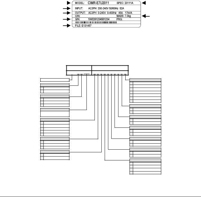
Drive Nameplate Information
A nameplate is also attached to the right side of the Drive inside the Bypass enclosure. The following nameplate is an example for a standard Drive.
Drive Model Number |
|
|
|
Drive Enclosure and |
|
|
|
Revision Code |
|
|
|
|
|
Input Power Specifications
Output Power Specifications
Weight
Serial Number
UL File Number
Fig 1.2 Drive Nameplate
(Example)
Bypass Unit Model Numbers
The model number on the nameplate of the Bypass unit indicates the enclosure, voltage, Drive rated current and options of the Bypass unit in alphanumeric codes.
E7BVB096RSL
BASE NUMBER |
OPTIONS |
|
|
E 7 B
E7 3-Contactor Bypass
Enclosure
V NEMA 1
B NEMA 12
Voltage
D 208V
A230/240V
B480V
Current
NEC Rated Amps (Ex.: “096” = 96A)
Motor Control
T Touchpad & LED
Y Touchpad & LCD
0 22mm Operators & LCD
D 2 Motor “OR” (4)
A 2 Motor “AND” (4)
Input Filter
0 None (leave blank) N Cap Filter
E RFI Filter
Input Fuses
0 None (leave blank)
FFuses
(1)3% and 5% Bus Reactors are only available as an option on base numbers up to E7B_D074, A068, and B040; larger drives have a Bus Reactor as standard.
(2)3% Input Reactor, when combined with the standard Bus Reactor (available on base numbers E7B_D088, A080, and B052 and above), yields a total of 5% input impedance.
(3)Serial Comm options (J), (L), (U) or (V) cannot be ordered if both (S) and (P) are combined.
(4)2 Motor “OR” and 2 Motor “AND” options (D) and (A) are only available with 22mm operators option (0).
(5)Options (M) and (S) are not available with options (T) or (Y) - 4-20mA output is standard with options (T) or (Y).
(6)Not available with options (T) or (Y).
Communications (3)
0 Not Enabled (leave blank)
2EtherNet/IP (6) L LonWorks
J Enable METASYS N2 U Enable APOGEE FLN V Enable Modbus
3BACnet
4-20mA Output
0 None (leave blank) M 4-20 mA Output (5)
3-15 PSI Transducer (3)
0 None (leave blank)
P 3-15 PSI Transducer
Speed Pot (3)
0 None (leave blank)
S Speed Pot (5)
Custom Nameplates
0 None (leave blank) W Custom Nameplates
Load Reactor
0 None (leave blank) K 5% Load Reactor
Line Impedance
0 None (leave blank)
X 3% Bus Reactor (1)
Z 5% Bus Reactor (1)
R 3% Input Reactor (2)
Fig 1.3 Bypass Unit Model Number
Bypass Unit Enclosures
All Bypass units are intended for non-hazardous locations. Various enclosure types are provided to protect against the application environmental conditions:
Nema Type 1 Enclosures are constructed for indoor use to provide a degree of protection against incidental contact with enclosed electrical equipment and falling dust or dirt.
NEMA Type 12 FVFF Enclosures. NEMA provides for both non-ventilated and ventilated NEMA 12 enclosures. When ventilated, a suffix to the type number defines the ventilation method. A NEMA 12 FVFF enclosure has Forced Ventilation with inlet air Filter and outlet air Filter. The internal pressure is positive with respect to the ambient pressure. UL does not recognize NEMA 12 ventilated enclosures, therefore, these enclosures are designated NEMA 1 for UL purposes.
Physical Installation 1 - 8
Bypass Product Options
Option A - Two motor “AND” control: Allows the operation of two motors from one Drive or Bypass. Pump #1 “AND” pump #2 are operated at the same speed via the output from one Drive or Bypass. The motors are always operated simultaneously therefore, no transfer switch is involved. With the 2 motor “AND” option, motor OverLoad Relays and fuses are provided for each motor and the Drive’s internal motor overload function is disabled.
The two motors can be of different capacity if this capacity difference was considered in the ordering process. The factory needs to know the FLA value of each motor controlled in order to select the correct motor overload devices and fuses. (Specifying different capacity motors results in longer, non-standard lead times).
Option D - Two motor “OR” control: A MTR #1/AUTO/MTR #2 selector switch is provided to allow local or remote motor operation selection, between two identical motors, for control by either the Drive or the Bypass (for example, Pump #1 “OR” AUTO “OR” Pump #2). In the AUTO position a contact closure from a BAS, at TB1 terminals 23 and 24, can switch between the two motors. The two motors must be the same horsepower and current draw.
Option E - RFI/EMI Filter: Filters to further attenuate possible VFD generated noise. Radio frequency interference/electro magnetic interference filters reduce conducted noise on the Drive input power leads and therefore, radiated noise from those leads. This option is installed on the input power side of the Drive, between the input contactor and the Drive.
Option F - Drive Input Fuses: Fuses capable of protecting semiconductor devices, rated at 200 kAIC are connected to the line side of the Drive, between the input contactor and the Drive, to protect the Drive semiconductors when motor or output conductor short circuit faults occur.
Option J - Enable Embedded Serial Communications: A no cost option. The Drive in a Bypass unit is capable of network communication via one of 3 embedded protocols. Specifying option J and the protocol to be employed (Metasys, APOGEE or Modbus) will provide the necessary parameter settings and wiring (jumpers) to be network ready when delivered (Project specific H5-0X parameters are setup by the user).
Option K - 5% Output Reactor: Employed on the output side of the Drive for reduction of peak voltages applied to the driven motor. In long Drive to motor lead length situations, high carrier frequency and reflected waves can cause high voltage spikes at the motor. An output reactor provides motor protection in these long motor lead length situations. This option is installed on the output power side of the Drive, between the output contactor and the Drive.
Option L - Serial Communication, Echelon LonWorks: An isolated RS-422/485 circuit board provides LonTalk protocol for network communication to a BAS. This option plugs into the CN2 connection on the Drive control circuit board.
Option M - 4 to 20 mA Output: Provides two programmable 0 to 10 VDC analog outputs or two programmable 4 to 20 mA analog outputs.
Option N - Input Capacitive Network Radio Frequency Interference Filter: Electronic equipment can be sensitive to low levels of voltage distortion and electrical noise. This passive wye-delta capacitve filter is intended for installation on the VFD input in order to protect other sensitive electronic loads, it provides attenuation of conducted RFI and EMI.
Option P - Pressure to Electrical Transducer: This transducer is employed when converting a pneumatic signal to an electrical signal for use as the Drive speed command input. The need for this option comes up on retrofit applications when the pneumatic signal that formerly controlled the pneumatic actuator on Inlet Guide Vanes (IGV), for example, is now to be used to control the fan speed via the Drive. This option is wired to Drive terminals +V, A2 and AC, parameters H3-10 and
H3-11 are used for final field calibration of this input if there is jobsite variation from the typical 3 to 15 PSIG pneumatic signal input range.
Physical Installation 1 - 9
Option R - 3% Input Line Reactor: Employed on the input side of the Drive for Total Harmonic Distortion (THD) suppression. A line reactor also minimizes the potential for Drive input diode damage from line transients and reduces voltage peaks on the DC bus capacitors. This option is installed on the input power side of the Drive, between the input contactor and the Drive.
Option S - Speed Potentiometer: A door mounted single turn potentiometer for manual control of Drive output and motor speed. This option is wired to Drive terminals +V, A1 and AC and is used as the local speed command input to the Drive instead of the keypad up and down arrows. Parameters for use of this option in conjunction with other input signals are detailed in Table 5.2.
Option W - Engraved Plastic Nameplate: An enclosure identification nameplate to carry the controlled equipment “tag number”.
Option X - 3% DC Bus Reactor: Attenuates harmonic distortion by limiting the rate of rise of the input current. The bus reactor is wired to the Drive (+1) and (+2) DC bus terminals to provide the equivalent impedance of a 3% input reactor. This option is only used on the low end of the horsepower range where DC bus reactors are not a standard Drive component (25 HP and below @ 208 VAC, 25 HP and below @ 240 VAC, and 30 HP and below @ 480 VAC.)
Option Z - 5% DC Bus Reactor: Attenuates harmonic distortion by limiting the rate of rise of the input current. The bus reactor is wired to the Drive (+) and (-) DC bus terminals to provide the equivalent impedance of a 5% input reactor. This option is only used on the low end of the horsepower range where DC bus reactors are not a standard Drive component (25 HP and below @ 208 VAC, 25 HP and below @ 240 VAC, and 30 HP and below @ 480 VAC.)
Physical Installation 1 - 10
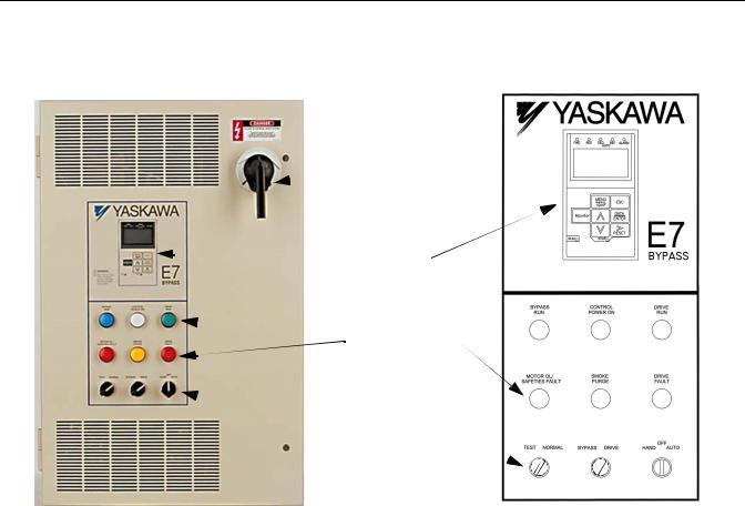
Bypass Component Descriptions
Bypass Unit Front Control Panel
The external appearance, component names, and terminal arrangement of the Bypass unit is shown in Figures 1.4 through 1.8.
MCP
 Disconnect
Keypad
Operator
 Indicating Lights

 Selector Switches
Fig 1.4 E7 Bypass Unit Appearance
Keypad Operator
In a Bypass unit the keypad operator is mounted flush with the hinged door of the enclosure. The addition of a HAND/ OFF/AUTO selector switch for the Bypass logic circuit makes the Hand, Off and Auto keys on the standard Drive keypad operator redundant. In this Bypass configuration the keypad Hand, Off and Auto keys are disabled in the Drive firmware and a mask (membrane) is placed over the keypad operator to cover these keys, avoiding the potential for confusion. The membrane over the Drive keypad is non-removable on these Bypass units (In order to use the keypad copy function on a Bypass unit - order a separate keypad, part number CDR001115).
Indicating Lights
On the enclosure door just below the digital operator are six 22 mm, 24 VAC LED indicating lights for: “Control Power”, “Drive Run”, “Bypass Run”, “Motor OL/Safeties Fault “Drive Fault” and “Smoke Purge”. LED type indicating lights are provided to improve the reliability well beyond that of incandescent bulbs. LED’s have a MTBF of 100K hours, eliminating any need for “push to test” type pilot lights.
Physical Installation 1 - 11
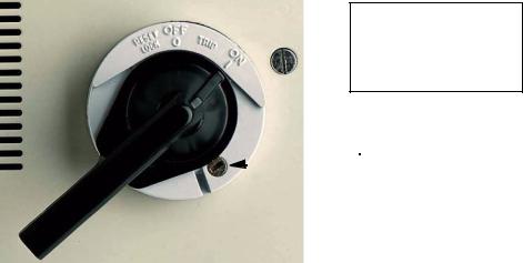
HAND/OFF/AUTO Selector Switch
A three position rotary switch employed to control the source of the motor start and speed commands in either the Drive or Bypass operating modes.
Hand Position – Drive Mode: The Drive input and output contactors are energized and the Drive is given a run command. Operation is via the local speed input from the keypad or optional speed potentiometer.
Hand Position – Bypass Mode: The Bypass contactor is energized causing the motor to run at full speed directly across-the- line.
Off Position: No power is applied to the Bypass circuit. The Drive input and output contactors are energized and the Drive is stopped (run command removed). The Off position takes precedence over a serial communication run command.
Auto Position – Drive Mode: The Drive input and output contactors are energized. The Drive is enabled to receive a run command contact closure and speed input analog signal from a Building Automation System (BAS).
Auto Position – Bypass Mode: The motor full speed across-the-line run/stop is controlled by a BAS contact closure, energizing the Bypass contactor.
The H/O/A switch must be in the AUTO position if serial communication is to be used for Drive run, stop and speed control.
DRIVE/BYPASS Selector Switch
A two position rotary switch selecting motor operation from the Drive or directly across-the-line. When transferring from Drive operation to Bypass operation, the logic circuit will require the Bypass unit to stop the motor before completing the transfer to full speed across-the-line operation.
NORMAL/TEST Selector Switch
A two position rotary switch, test position is used to energize the Drive input contactor while operating in the Bypass mode (via the HAND or AUTO switch position). In Drive mode switching from NORMAL to TEST position will remove the power from the Drive and the motor will stop. In Bypass mode the test position powers the Drive for programming or other “tests” while keeping it isolated from the motor.
MCP Motor Circuit Protector Circuit Breaker/Disconnect
Electrically located on the input power side of the Bypass unit, the MCP adjustable, instantaneous trip circuit breaker
provides protection from short circuits for the motor power cables. The Bypass three phase input power connection is made to the input terminals of the MCP. The door mounted rotary operating mechanism is a convenient means of disconnecting the Bypass unit from line power for equipment maintenance. The MCP must be in the OFF position in order to open the enclosure door. Service and troubleshooting personnel are provided with a means to defeat this door interlock. The rotary handle provides trip indication and can be padlocked in the OFF position.
CAUTION
Only qualified service personnel should use the defeater feature.
Defeater
Fig 1.5 MCP Handle Positions – RESET/LOCK, OFF, TRIP, ON Shown in the “ON” position
Physical Installation 1 - 12
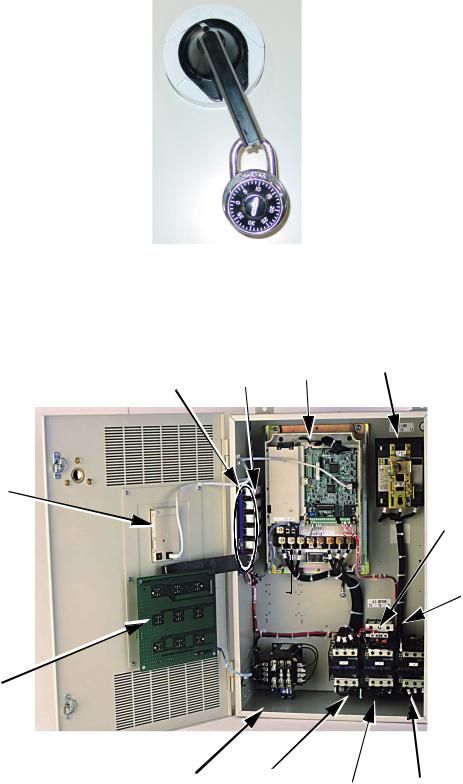
Fig 1.6 MCP Handle Positions – Shown OFF, With Padlock
Internal Bypass Panel
Customer Wiring
Terminal Strip (TB1)
Digital Operator 
PCB A3 
Control Power
Transformer
|
Line |
PCB A2 Drive |
Connections |
|
Motor Circuit

 Protector
Load
 Connections
Overload
Relay
Input |
|
Output |
Contactor |
Bypass |
|
(K1) |
Contactor |
Contactor |
|
(K3) |
(K2) |
Fig 1.7 Internal Bypass Panel
Physical Installation 1 - 13
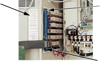
TB1 Label Defining |
|
|
Customer Control |
|
|
Circuit Connection |
TB1 with Terminal Numbers |
|
Points |
||
Printed on the PCB |
||
|
|
Slide Switches for switch |
|
selectable functions (Auto |
|
Transfer, Remote Transfer and |
Fig 1.8 Control Terminal Strip |
Smoke Purge) are behind this |
ribbon cable connector. See |
|
|
Fig. 1.9 for details. |
Contactors
The Bypass is a “3 contactor Bypass” circuit employing IEC rated contactors in an electrically interlocked arrangement to allow mutually exclusive operation in Drive or Bypass modes. To minimize enclosure space requirements, they are mounted in a 3 contactor assembly.
The control logic and “soft start” characteristic of the Drive limit the Drive input and output contactors to motor FLA current or less. For this reason, the Drive input and output contactors have lower current ratings than the Bypass contactor. The Bypass contactor is exposed to motor inrush current (LRA) when starting the motor across-the-line and therefore requires a higher current rating.
OverLoad Relay
The OverLoad Relay (OLR) is mounted to the contactor assembly or back panel (depending on rating), just above the Bypass contactor (see Figure 1.7). Electrically on the output power side of the Bypass unit, the adjustable thermal OLR provides overload protection for the motor in both the Drive and Bypass operating modes. The Bypass three phase output power connection to the motor is made to the output terminals of the overload relay. The OLR is set up in the factory to be a manual reset device, requiring operator attention if an overload trip-out is experienced.
Control Power Transformer
A Control Power Transformer (CPT) is provided to power the Bypass 120 VAC control circuit. The VA capacity is determined by the control circuit and optional functions specified for the unit. 100 VA of extra transformer capacity for customer control logic is provided in the standard unit and additional capacity is available as an “engineered” or “custom” option. The CPT primary is fused in both legs, the secondary is fused when required by NEC (above 350 VA). One side of the transformer secondary is grounded to the Bypass enclosure.
Relay and Selector Switch Logic
Operating elements such as indicating lights and selector switches, as well as the control relay logic, have been incorporated into a PCB assembly to eliminate the potential for loose wires after shipment and to control factory costs.
The operating elements are located on PCB A3, mounted to the inside of the enclosure door and ribbon cable connected to the control relay logic PCB A2.
The control relay logic PCB A2 is mounted to the left hand side of the enclosure and contains the control circuit field wiring terminal strip (TB1).
Drive/Bypass logic interlocks explained
The Bypass 120 VAC relay logic circuit is interconnected with the Drive multi-function digital input terminals and multifunction digital output terminals to allow a single customer interface to control both Drive and Bypass circuits. Some of these terminals are therefore not available for other field use.
Physical Installation 1 - 14
Drive Multi-function input terminals:
Terminal S1 receives the Drive run command from the 120 VAC relay logic circuit. Terminal S3 receives the Drive run enable signal from the 120 VAC relay logic circuit.
Terminal S5 receives the Drive local/remote command from the 120 VAC relay logic circuit via the HAND/OFF/ AUTO and NORMAL/TEST selector switch.
Drive Multi-function output terminals:
Terminals M1 and M2 are a normally open Drive run relay contact used to communicate the Drive operational mode to the 120 VAC relay logic circuit.
Terminals M3 and M4 are a normally open serial com. run status relay contact used to communicate the Drive operational state to the 120 VAC relay logic circuit.
Terminals MA and MC are a normally open Drive fault relay contact used to communicate the Drive fault status to the 120 VAC relay logic circuit.
PCB Jumpers explained
The S101 “Berg pin” jumper on the control relay logic PCB A2 is not for field use. It is employed only in the factory to enable the 2 motor “OR” configured option. It is removed when this option is present and must be in place when this option is not part of the unit specification (See Figure 1.9).
The S102 “Berg pin” jumper on the control relay logic PCB A2 is not for field use. It is employed only in the factory to enable the Run/Stop Push Button (3 wire control) configured option. It is removed when this option is present and must be in place when this option is not part of the unit specification (See Figure 1.9).
TB1 terminals 1 and 2 are jumpered (J1) as the unit is shipped from the factory. If a customer supplied series circuit of NC safety devices is to be used, this jumper is removed and the safety circuit connected between terminals 1 and 2.
TB1 terminals 5 and 6 are jumpered (J2) as the unit is shipped from the factory. If a customer supplied Drive NO enabling contacts are to be used (such as a damper end switch or occupied cycle timer), this jumper is removed and the enabling contacts wired between terminals 5 and 6.
Physical Installation 1 - 15
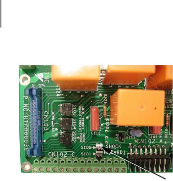
Switch Selectable Functions:
The slide switches used to select these functions are located on the relay controller Printed Circuit Board (PCB) A2 (See Figure 1.9). The factory default is for these functions to be de-selected.
Smoke Purge: When enabled (switch S105) this function allows a contact closure, between terminals 17 and 18 of TB1, to transfer motor operation to bypass for a maximum capacity smoke control function. When in smoke purge mode, during emergency fire/smoke situations, the motor overloads and safety interlock circuit are overridden to shift the priority to protecting people rather than equipment.
Auto Transfer to Bypass: If enabled (switch S103), the E7 Bypass unit will automatically transfer the motor operation from Drive to Bypass in the event of a Drive fault. When the Drive fault condition has cleared, this function is reset by moving the circuit breaker to the OFF position, waiting for the keypad to go blank, then switching back to the DRIVE position.
Before selecting this function in fan applications, care must be taken to ensure that the duct-work is IMPORTANT designed to handle the pressure resulting from full speed operation with the VAV terminal unit dampers at
minimum position or closed.
Remote Transfer to Bypass: When selected (switch S104) this function allows a contact closure from a BAS, between terminals 25 and 26 of TB1, to transfer motor operation from Drive mode to Bypass mode. This remote tranfer to Bypass function overrides the DRIVE/BYPASS manual switch.
Slide Switches 

 PCB Jumpers
Fig 1.9 Printed Circuit Board A2
Physical Installation 1 - 16
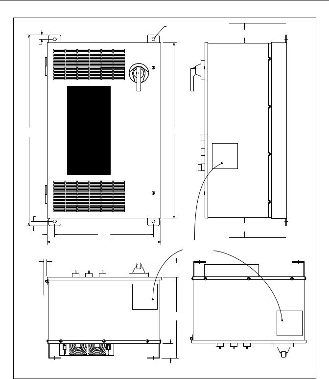
Exterior and Mounting Dimensions
Bypass Unit 30 HP and Below, 480 VAC; 15 HP and Below, 208V/240V
|
|
|
|
Ø0.50(4PLS) |
|
|
|
|
|
(Ø12.7) |
|
|
|
|
|
|
MIN. 6 |
|
|
|
|
|
(152.4) |
0.75 |
|
|
|
|
|
(19) |
|
|
|
|
|
|
|
MENU |
ESC |
|
|
|
|
Monitor |
DATA |
|
|
|
|
ENTER |
|
|
|
|
|
|
RESET |
|
|
32.00 |
|
|
|
DRIVE |
29.48 |
(812.8) |
|
|
|
RUN |
(748.8) |
|
|
|
|
||
|
|
|
|
|
|
MOTOR OL/ |
SMOKE |
|
DRIVE |
|
|
SAFETIES FAULT |
PURGE |
|
FAULT |
|
|
TEST |
NORMAL |
|
|
OFF |
|
BYPASS DRIVE |
HAND AUTO |
|
|||
0.75 |
|
|
|
|
|
(19) |
|
|
|
|
|
|
|
|
|
|
MIN. 6 |
|
|
|
|
|
(152.4) |
1.29 |
|
|
|
16.50 |
|
|
|
|
(419.1) |
|
|
(32.8) |
|
|
|
|
|
|
|
|
|
19.06 |
RECOMMENDED |
|
|
|
|
(484.1) |
|
|
|
|
|
|
CONDUIT |
|
|
|
|
|
ENTRANCE AREA |
|
|
|
|
|
TOP, BOTTOM |
|
|
|
|
|
AND SIDE |
MIN. 1.50 |
|
|
|
|
|
(3.81) |
|
|
|
|
2.37 |
|
|
|
|
|
|
|
|
|
|
|
(60.2) |
|
|
|
|
|
13.66 |
|
|
|
|
|
(347) |
|
|
|
|
2.50 |
|
|
|
|
|
(63.5) |
|
|
|
|
|
|
TOP VIEW |
DIMENSIONS IN INCHES (MM), FOR REFERENCE ONLY
Fig 1.10 Enclosure 1 for up to 30HP, 480 VAC
NEMA 1 and NEMA 12 FVFF Enclosures
Physical Installation 1 - 17

Bypass Unit 30 HP and Below, 480 VAC; 15 HP and Below, 208V/240V With Add-On Box
|
|
|
|
|
|
19.06 |
|
|
|
1.29 |
|
16.50 |
|
|
(484.1) |
|
|
|
|
|
|
|
|
|
|
|
|||
(32.8) |
|
(419.1) |
|
|
|
Ø0.50(4PLS) |
|
|
|
|
|
|
|
|
|
|
(Ø12.7) |
MIN. 6 |
|
|
|
|
|
|
|
|
|
|
|
|
|
|
|
|
|
|
|
(152.4) |
|
0.75 |
|
|
|
|
|
|
|
|
|
(19) |
|
|
|
|
|
|
|
|
|
32.00 |
|
|
|
|
|
|
29.48 |
|
|
(812.8) |
BYPASS |
CONTROL |
|
DRIVE |
|
(748.8) |
|
|
|
|
RUN |
POWER ON |
|
RUN |
|
|
|
|
|
|
MOTOR OL/ |
SMOKE |
|
DRIVE |
|
|
|
|
|
|
SAFETIES FAULT |
PURGE |
|
FAULT |
|
|
|
|
|
|
TEST NORMAL |
BYPASS DRIVE |
|
OFF |
AUTO |
|
|
|
|
|
HAND |
|
|
|
|
||||
44.60 |
|
|
|
|
|
|
|
|
|
(1132.8) |
|
|
|
|
|
|
43.35 |
|
|
|
|
|
|
|
|
|
(1,101.2) |
|
|
0.75 |
|
|
|
|
|
|
|
|
|
(19) |
|
|
|
|
|
|
|
|
|
|
|
|
|
|
|
|
13.87 |
|
|
12.60 |
|
|
|
|
|
|
(3.81) |
|
|
(317.5) |
|
|
|
|
|
|
|
|
|
|
|
13.50 |
|
|
|
5.37 |
|
9.1 |
3.375 |
|
|
|
|
|
|
(231.1) |
(85.7) |
||
|
|
(342.9) |
|
|
|
(136.4) |
RECOMMENDED |
||
|
|
|
|
|
|
|
|||
|
|
|
|
|
|
|
|
|
|
|
|
|
|
|
|
|
CONDUIT |
|
|
|
|
|
|
|
|
|
ENTRANCE AREA |
|
|
|
|
|
|
|
|
|
TOP, BOTTOM |
|
|
|
|
|
|
|
|
|
AND SIDE |
|
|
|
MIN. 1.50 |
|
|
|
|
|
|
|
|
|
(3.81) |
|
|
|
|
|
2.37 |
|
|
|
|
|
|
|
|
|
|
|
|
|
|
|
|
|
|
|
(60.2) |
|
|
|
|
|
|
|
|
|
13.66 |
|
|
|
|
|
|
|
|
|
(347) |
|
|
|
|
|
|
|
|
|
2.50 |
|
|
|
|
|
|
|
|
|
(63.5) |
|
|
|
|
|
|
|
|
|
|
TOP VIEW |
|
DIMENSIONS IN INCHES (MM), FOR REFERENCE ONLY
Fig 1.11 Enclosure 1, with Options Extension, for up to 30HP, 480 VAC
NEMA 1 and NEMA 12 FVFF Enclosures
Physical Installation 1 - 18
Loading...