


 Loading...
YASKAWA AC Drive V1000
Compact Vector Control Drive
Quick Start Guide
Type: CIMR-VA 
 , CIMR-VT

Models: 200 V Class, Three-Phase Input: 0.1 to 18.5 kW 200 V Class, Single-Phase Input: 0.1 to 3.7 kW 400 V Class, Three-Phase Input: 0.2 to 18.5 kW
To properly use the product, read this manual thoroughly and retain for easy reference, inspection, and maintenance. Ensure the end user receives this manual.
Receiving
Mechanical
Installation
Electrical
Installation
Start-Up Programming
& Operation
Troubleshooting
Specifications
Parameter List
Standards
Compliance
1
2
3
4
5
6
7
8
MANUAL NO. TOEP C710606 12B

2 |
YASKAWA ELECTRIC TOEP C710606 12B YASKAWA AC Drive V1000 Quick Start Guide |

|
Table of |
|
|
Contents |
|
i. PREFACE & GENERAL SAFETY .................................. |
7 |
|
|
i.1 Preface. . . . . . . . . . . . . . . . . . . . . . . . . . . . . . . . . . . . |
8 |
|
Applicable Documentation . . . . . . . . . . . . . . . . . . . . . . . . . |
. 8 |
|
i.2 General Safety . . . . . . . . . . . . . . . . . . . . . . . . . . . . . |
9 |
|
Supplemental Safety Information . . . . . . . . . . . . . . . . . . . . |
. 9 |
|
Safety Messages . . . . . . . . . . . . . . . . . . . . . . . . . . . . . . . . |
11 |
|
Drive Label Warnings . . . . . . . . . . . . . . . . . . . . . . . . . . . . . |
14 |
1. |
RECEIVING ................................................................... |
15 |
|
1.1 Model Number and Nameplate Check . . . . . . . . . |
16 |
|
Nameplate . . . . . . . . . . . . . . . . . . . . . . . . . . . . . . . . . . . . . |
16 |
2. |
MECHANICAL INSTALLATION ................................... |
19 |
2.1 Mechanical Installation . . . . . . . . . . . . . . . . . . . . . 20
Installation Environment . . . . . . . . . . . . . . . . . . . . . . . . . . . 20
Installation Orientation and Spacing . . . . . . . . . . . . . . . . . . 21
Exterior and Mounting Dimensions . . . . . . . . . . . . . . . . . . . 23
YASKAWA ELECTRIC TOEP C710606 12B YASKAWA AC Drive V1000 Quick Start Guide |
3 |

3.
4.
4
ELECTRICAL INSTALLATION..................................... |
29 |
3.1 Standard Connection Diagram . . . . . . . . . . . . . . . 30
3.2 Main Circuit Wiring . . . . . . . . . . . . . . . . . . . . . . . . 33
Main Circuit Terminal Functions . . . . . . . . . . . . . . . . . . . . . 33
Wire Gauges and Tightening Torque . . . . . . . . . . . . . . . . . 33
Main Circuit Terminal Power Supply and Motor Wiring . . . 36
Control Circuit Terminal Block Functions . . . . . . . . . . . . . . 38
Removable Terminal Block Configuration . . . . . . . . . . . . . 41
Wiring Procedure . . . . . . . . . . . . . . . . . . . . . . . . . . . . . . . . 43
3.3 I/O Connections . . . . . . . . . . . . . . . . . . . . . . . . . . . 45
Sinking/Sourcing Mode Switch . . . . . . . . . . . . . . . . . . . . . . 45
3.4 Main Frequency Reference . . . . . . . . . . . . . . . . . . 47
Terminal A2 Switch . . . . . . . . . . . . . . . . . . . . . . . . . . . . . . 47
3.5 Wiring Checklist. . . . . . . . . . . . . . . . . . . . . . . . . . . 49
START-UP PROGRAMMING & OPERATION ............. |
51 |
4.1 Using the Digital LED Operator . . . . . . . . . . . . . . 52
Keys, Displays, and LEDs . . . . . . . . . . . . . . . . . . . . . . . . . 52 LED Screen Displays . . . . . . . . . . . . . . . . . . . . . . . . . . . . . 54 LO/RE LED and RUN LED Indications . . . . . . . . . . . . . . . . 54 Menu Structure for Digital LED Operator . . . . . . . . . . . . . . 55
4.2 The Drive and Programming Modes . . . . . . . . . . 56
Changing Parameter Settings or Values . . . . . . . . . . . . . . 56 Switching Between LOCAL and REMOTE . . . . . . . . . . . . . 57 Parameters Available in the Setup Group . . . . . . . . . . . . . 58
4.3 Start-up Flowcharts . . . . . . . . . . . . . . . . . . . . . . . . 59
Flowchart A: Basic Start-Up and Motor Tuning . . . . . . . . . 59 Subchart A1: Simple Motor Set-Up with Energy Savings
or Speed Search using V/f Mode . . . . . . . . . . . . . . . . . . . . 61 Subchart A2: High Performance Operation Using
Open Loop Vector Motor Control . . . . . . . . . . . . . . . . . . . . 62
YASKAWA ELECTRIC TOEP C710606 12B YASKAWA AC Drive V1000 Quick Start Guide

Subchart A3: Operation with Permanent Magnet Motors . 63
4.4 Application Presets . . . . . . . . . . . . . . . . . . . . . . . .64
Application Preset Function (APPL) . . . . . . . . . . . . . . . . . 64 Application Presets: A1-06 . . . . . . . . . . . . . . . . . . . . . . . . 64
4.5 Basic Drive Setup Adjustments. . . . . . . . . . . . . . .66
Control Mode Selection: A1-02 . . . . . . . . . . . . . . . . . . . . . 66 Initialize Parameter Values: A1-03 . . . . . . . . . . . . . . . . . . 66 Frequency Reference Source: b1-01 . . . . . . . . . . . . . . . . 67 Run Command Input Selection: b1-02 . . . . . . . . . . . . . . . 69 Drive Duty Mode and Carrier Frequency Selection:
C6-01 and C6-02 . . . . . . . . . . . . . . . . . . . . . . . . . . . . . . . 71 Drive Input Voltage Setting: E1-01 . . . . . . . . . . . . . . . . . . 72
4.6 Test Run. . . . . . . . . . . . . . . . . . . . . . . . . . . . . . . . . .73
Powering Up the Drive and Operation Status Display . . . 73 Auto-Tuning . . . . . . . . . . . . . . . . . . . . . . . . . . . . . . . . . . . 73 Operating with the Load Connected . . . . . . . . . . . . . . . . . 78
4.7 Test Run Checklist . . . . . . . . . . . . . . . . . . . . . . . . .79
5. TROUBLESHOOTING .................................................. |
81 |
5.1 Drive Alarms, Faults, and Errors . . . . . . . . . . . . . . |
82 |
Types of Alarms, Faults, and Errors . . . . . . . . . . . . . . . . . |
82 |
5.2 Fault Detection . . . . . . . . . . . . . . . . . . . . . . . . . . . .83
Fault Displays, Causes, and Possible Solutions . . . . . . . . 83
5.3 Alarm Detection . . . . . . . . . . . . . . . . . . . . . . . . . . .96
Alarm Codes, Causes, and Possible Solutions . . . . . . . . . 96
5.4 Operator Programming Errors. . . . . . . . . . . . . . . .99 oPE Codes, Causes, and Possible Solutions . . . . . . . . . . 99
5.5 Auto-Tuning Fault Detection . . . . . . . . . . . . . . . .100
Auto-Tuning Codes, Causes, and Possible Solutions . . 100
5.6 Diagnosing and Resetting Faults . . . . . . . . . . . .103
Fault Reset Methods . . . . . . . . . . . . . . . . . . . . . . . . . . . . 103
YASKAWA ELECTRIC TOEP C710606 12B YASKAWA AC Drive V1000 Quick Start Guide |
5 |

6.
7.
8.
6
SPECIFICATIONS....................................................... |
105 |
6.1 Heavy Duty and Normal Duty Ratings . . . . . . . . 106 6.2 Single/Three-Phase 200 V Class Drive. . . . . . . . 107 6.3 Three-Phase 400 V Class Drives . . . . . . . . . . . . 110
PARAMETER LIST ..................................................... |
113 |
7.1 Parameter Table . . . . . . . . . . . . . . . . . . . . . . . . . . |
114 |
STANDARDS COMPLIANCE ..................................... |
143 |
8.1 European Standards . . . . . . . . . . . . . . . . . . . . . . 144
CE Low Voltage Directive Compliance . . . . . . . . . . . . . . . 144
EMC Guidelines Compliance . . . . . . . . . . . . . . . . . . . . . . 146
8.2 UL Standards . . . . . . . . . . . . . . . . . . . . . . . . . . . . 151
UL Standards Compliance . . . . . . . . . . . . . . . . . . . . . . . . 151
Drive Motor Overload Protection . . . . . . . . . . . . . . . . . . . 154
8.3 Safe Disable Input Precautions . . . . . . . . . . . . . 156
Safe Disable Function Description . . . . . . . . . . . . . . . . . . 156
Installation . . . . . . . . . . . . . . . . . . . . . . . . . . . . . . . . . . . . 156
YASKAWA ELECTRIC TOEP C710606 12B YASKAWA AC Drive V1000 Quick Start Guide

i
Preface &
General Safety
This section provides safety messages pertinent to this product, that, if not heeded, may result in fatality, personal injury, or equipment damage. Yaskawa is not responsible for the consequences of ignoring these instructions.
I.1 PREFACE . . . . . . . . . . . . . . . . . . . . . . . . . . . . . . . . . . . . . . . 8 I.2 GENERAL SAFETY. . . . . . . . . . . . . . . . . . . . . . . . . . . . . . . . 9
YASKAWA ELECTRIC TOEP C710606 12B YASKAWA AC Drive V1000 Quick Start Guide |
7 |
i.1 Preface
i.1 Preface
This manual is designed to ensure correct and suitable application of variable V1000-Series Inverters. Read this manual before attempting to install, operate, maintain, or inspect an inverter and keep it in a safe, convenient location for future reference. Understand all precautions and safety information before attempting application.
Applicable Documentation
The following manuals are available for V1000 series drives:


 STOP
STOP
V1000
|
(Hz) |
|
|
|
(Hz) |
|
(A) |
|
(V) |
|
|
|
|
|
|
|
|
|
|
5
400V
V1000 Series AC Drive Installation & Start-Up Manual
Read this manual first.
This manual describes installation, wiring, operation procedures, functions, troubleshooting, maintenance, and inspections to perform before operation.
V1000 Series AC Drive Technical Manual
Read this manual for detailed information about parameter usage. Contact a Yaskawa representative to order this manual.
V1000 Series AC Drive Quick Start Guide
This guide is packaged together with the product. It contains basic information required to install and wire the drive. This guide provides basic programming and simple set-up and adjustment. Refere to the V1000 Technical Manual for complete descriptions of drive features and functions.
8 |
YASKAWA ELECTRIC TOEP C710606 12B YASKAWA AC Drive V1000 Quick Start Guide |
i.2 General Safety
i.2 General Safety
Supplemental Safety Information
General Precautions
•The diagrams in this manual may be indicated without covers or safety shields to show details. Restore covers or shields before operating the drive and run the drive according to the instructions described in this manual.
•Any illustrations, photographs, or examples used in this manual are provided as examples only and
may not apply to all products to which this manual is applicable.
•The products and specifications described in this manual or the content and presentation of the manual may be changed without notice to improve the product and/or the manual.
•When ordering a new copy of the manual due to damage or loss, contact your Yaskawa representative or the nearest Yaskawa sales office and provide the manual number shown on the front cover.
•If nameplate becomes worn or damaged, order a replacement from your Yaskawa representative or the nearest Yaskawa sales office.
Preface & General Safety
i
 WARNING
Read and understand this manual before installing, operating or servicing this drive. The drive must be installed according to this manual and local codes.
The following conventions are used to indicate safety messages in this manual. Failure to heed these messages could result in serious or possibly even fatal injury or damage to the products or to related equipment and systems.
 DANGER
Indicates a hazardous situation, which, if not avoided, will result in death or serious injury.
YASKAWA ELECTRIC TOEP C710606 12B YASKAWA AC Drive V1000 Quick Start Guide |
9 |
i.2 General Safety
 WARNING
Indicates a hazardous situation, which, if not avoided, could result in death or serious injury.
WARNING! will also be indicated by a bold key word embedded in the text followed by an italicized safety message.
 CAUTION
Indicates a hazardous situation, which, if not avoided, could result in minor or moderate injury.
CAUTION! will also be indicated by a bold key word embedded in the text followed by an italicized safety message.
NOTICE
Indicates a property damage message.
NOTICE: will also be indicated by a bold key word embedded in the text followed by an italicized safety message.
10 |
YASKAWA ELECTRIC TOEP C710606 12B YASKAWA AC Drive V1000 Quick Start Guide |
i.2 General Safety
Safety Messages
 DANGER
Heed the safety messages in this manual.
Failure to comply will result in death or serious injury.
The operating company is responsible for any injuries or equipment damage resulting from failure to heed the warnings in this manual.
Electrical Shock Hazard
Do not connect or disconnect wiring while the power is on.
Failure to comply will result in death or serious injury.
Before servicing, disconnect all power to the equipment. The internal capacitor remains charged even after the power supply is turned off. The charge indicator LED will extinguish when the DC bus voltage is below 50 Vdc. To prevent electric shock, wait at least five minutes after all indicators are OFF and measure the DC bus voltage level to confirm safe level.
 WARNING
Sudden Movement Hazard
System may start unexpectedly upon application of power, resulting in death or serious injury.
Clear all personnel from the drive, motor and machine area before applying power. Secure covers, couplings, shaft keys and machine loads before applying power to the drive.
When using DriveWorksEZ to create custom programming, the drive I/O terminal functions change from factory settings and the drive will not perform as outlined in this manual.
Unpredictable equipment operation may result in death or serious injury.
Take special note of custom I/O programming in the drive before attempting to operate equipment.
Preface & General Safety
i
YASKAWA ELECTRIC TOEP C710606 12B YASKAWA AC Drive V1000 Quick Start Guide |
11 |
i.2 General Safety
 WARNING
Electrical Shock Hazard
Do not attempt to modify or alter the drive in any way not explained in this manual.
Failure to comply could result in death or serious injury.
Yaskawa is not responsible for any modification of the product made by the user. This product must not be modified.
Do not allow unqualified personnel to use equipment.
Failure to comply could result in death or serious injury.
Maintenance, inspection, and replacement of parts must be performed only by authorized personnel familiar with installation, adjustment and maintenance of AC drives.
Do not remove covers or touch circuit boards while the power is on.
Failure to comply could result in death or serious injury.
Fire Hazard
Do not use an improper voltage source.
Failure to comply could result in death or serious injury by fire.
Verify that the rated voltage of the drive matches the voltage of the incoming power supply before applying power.
 CAUTION
Crush Hazard
Do not carry the drive by the front cover.
Failure to comply may result in minor or moderate injury from the main body of the drive falling.
12 |
YASKAWA ELECTRIC TOEP C710606 12B YASKAWA AC Drive V1000 Quick Start Guide |

i.2 General Safety
NOTICE
Observe proper electrostatic discharge procedures (ESD) when handling the drive and circuit boards.
Failure to comply may result in ESD damage to the drive circuitry.
Never connect or disconnect the motor from the drive while the drive is outputting voltage.
Improper equipment sequencing could result in damage to the drive.
Do not perform a withstand voltage test on any part of the drive.
Failure to comply could result in damage to the sensitive devices within the drive.
Do not operate damaged equipment.
Failure to comply could result in further damage to the equipment.
Do not connect or operate any equipment with visible damage or missing parts.
Install adequate branch circuit short circuit protection per applicable codes.
Failure to comply could result in damage to the drive.
The drive is suitable for circuits capable of delivering not more than 30,000 RMS symmetrical Amperes, 240 Vac maximum
(200V Class) and 480 Vac maximum (400V Class).
Do not expose the drive to halogen group disinfectants.
Failure to comply may cause damage to the electrical components in the drive.
Do not pack the drive in wooden materials that have been fumigated or sterilized.
Do not sterilize the entire package after the product is packed.
Preface & General Safety
i
YASKAWA ELECTRIC TOEP C710606 12B YASKAWA AC Drive V1000 Quick Start Guide |
13 |
i.2 General Safety
Drive Label Warnings
Always heed the warning information listed in Figure i.1 in the position shown in
Figure i.2.
 WARNING Risk of electric shock.
 Read manual before installing.
 Wait 5 minutes for capacitor discharge after disconnecting power supply.
 To conform to
 requirements, make sure to ground the supply neutral for 400V class.
Figure i.1 Warning Information


 STOP
STOP
V1000
|
(Hz) |
|
|
|
(Hz) |
|
(A) |
|
(V) |
|
|
|
|
|
|
|
|
|
|
5
400V
Warning
Display
Figure i.2 Warning Information Position
14 |
YASKAWA ELECTRIC TOEP C710606 12B YASKAWA AC Drive V1000 Quick Start Guide |

1
Receiving
This chapter describes the proper inspections to perform after receiving the drive and illustrates the different enclosure types and components.
1.1 MODEL NUMBER AND NAMEPLATE CHECK. . . . . . . . .16
YASKAWA ELECTRIC TOEP C710606 12B YASKAWA AC Drive V1000 Quick Start Guide |
15 |
1.1 Model Number and Nameplate Check
1.1Model Number and Nameplate Check
Please perform the following tasks after receiving the drive:
•Inspect the drive for damage.
If the drive appears damaged upon receipt, contact the shipper immediately.
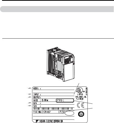
•Verify receipt of the correct model by checking the information on the nameplate.
•If you have received the wrong model or the drive does not function properly, contact your supplier.
Nameplate
Normal Duty Amps/Heavy Duty Amps
AC drive model |
%+/4 8# #$## |
|
|
/#: #22.+ /1614 M9 M9 4'8 # |
|
Input specifications |
#% 2* 8 *\ # |
|
Output specifications |
#% 2* 8 *\ # # |
|
Lot number |
|
|
|
Software version |
|
Serial number |
|
|
|
Enclosure Type |
|
|
|
|
|
+056#..#6+10 %#6')14;++ PASS |
|
|
/#&' +0 ,#2#0 |
RoHS |
Figure 1.1 Nameplate Information
16 |
YASKAWA ELECTRIC TOEP C710606 12B YASKAWA AC Drive V1000 Quick Start Guide |
1.1 Model Number and Nameplate Check
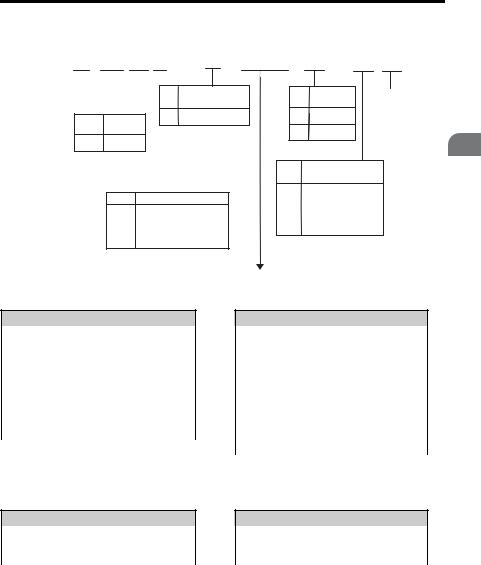
C I M R - V U 2 |
A 0 0 0 1 B |
A A |
|||||||||||||
|
|
|
|
|
|
|
|
|
|
|
|
|
|
|
|
Drive |
V1000 |
|
|
|
No. |
Customized |
No. |
Enclosure |
Design |
||||||
|
|
|
Series |
|
|
|
|
Specifications |
|
Type |
Revision |
||||
|
|
|
|
|
|
|
|
|
|
A |
Standard model |
B |
IP20 |
Order |
|
|
|
No. |
|
|
Region |
|
|
||||||||
|
|
|
|
|
|
|
|||||||||
|
|
|
|
|
|
|
|
|
|
|
|
||||
|
|
|
|
Code |
|
|
|
|
|
F |
NEMA1 |
|
|||
|
|
|
|
|
|
|
|
|
|
|
|||||
|
|
A |
|
|
|
Japan |
|
|
|
|
|
|
|||
|
|
|
|
|
|
|
|
|
|
|
|
|
|||
|
|
T |
|
|
|
Asia |
|
|
|
|
|
|
Environmental |
||
|
|
|
|
|
|
|
|
|
|
|
|
|
No. |
||
|
|
|
|
|
|
|
|
|
|
|
|
|
|||
|
|
|
|
|
|
|
|
|
|
|
|
|
Specification * |
||
|
|
|
|
|
|
|
|
|
|
|
|
|
|
||
|
|
|
|
|
|
No. |
|
|
Voltage Class |
A |
Standard |
|
|||
|
|
|
|
|
|
|
|
|
|||||||
|
|
|
|
|
|
|
|
M |
Humidityand |
||||||
|
|
|
|
|
|
B |
1-phase, 200-240 Vac |
|
|
dust-resistant |
|||||
|
|
|
|
|
|
N |
Oil-resistant |
|
|||||||
|
|
|
|
2 |
|
3-phase, 200-240 Vac |
|
|
|||||||
|
|
|
|
S |
Vibration-resistant |
||||||||||
|
|
|
4 |
|
3-phase, 380-480 Vac |
|
|
|
|||||||
Single-Phase 200 V
Normal Duty
No. |
Max. Motor |
Rated Output |
|
Capacity kW |
Current A |
||
|
|||
|
|
|
|
0001 |
0.2 |
1.2 |
|
|
|
|
|
0002 |
0.4 |
1.9 |
|
0003 |
0.75 |
3.3 |
|
|
|
|
|
0006 |
1.1 |
6 |
|
|
|
|
|
0010 |
2.2 |
9.6 |
|
0012 |
3.0 |
12 |
Heavy Duty
No. |
Max. Motor |
Rated Output |
|
Capacity kW |
Current A |
||
|
|||
|
|
|
|
0001 |
0.1 |
0.8 |
|
|
|
|
|
0002 |
0.2 |
1.6 |
|
0003 |
0.4 |
3 |
|
|
|
|
|
0006 |
0.75 |
5 |
|
|
|
|
|
0010 |
1.5 |
8 |
|
0012 |
2.2 |
11 |
|
|
|
|
|
0018 |
3.7 |
17.5 |
Note: CIMR-V BA0018 is available with a Heavy Duty rating only.
Three-Phase 200 V
Normal Duty
No. |
Max. Motor |
Rated Output |
|
Capacity kW |
Current A |
||
|
|||
|
|
|
|
0001 |
0.2 |
1.2 |
|
|
|
|
Heavy Duty
No. |
Max. Motor |
Rated Output |
|
Capacity kW |
Current A |
||
|
|||
|
|
|
|
0001 |
0.1 |
0.8 |
|
|
|
|
Receiving
1
YASKAWA ELECTRIC TOEP C710606 12B YASKAWA AC Drive V1000 Quick Start Guide |
17 |

1.1 Model Number and Nameplate Check
Normal Duty
0002 |
0.4 |
1.9 |
0004 |
0.75 |
3.5 |
|
|
|
0006 |
1.1 |
6 |
0008 |
1.5 |
8.0 |
0010 |
2.2 |
9.6 |
|
|
|
0012 |
3.0 |
12 |
0018 |
3.7 |
17.5 |
0020 |
5.5 |
19.6 |
|
|
|
0030 |
7.5 |
30 |
0040 |
11 |
40 |
0056 |
15 |
56 |
|
|
|
0069 |
18.5 |
69 |
Three-Phase 400 V
Heavy Duty
0002 |
0.2 |
1.6 |
0004 |
0.4 |
3 |
|
|
|
0006 |
0.75 |
5 |
0008 |
1.1 |
6.9 |
0010 |
1.5 |
8 |
|
|
|
0012 |
2.2 |
11 |
0018 |
3.0 |
14.0 |
0020 |
3.7 |
17.5 |
|
|
|
0030 |
5.5 |
25 |
0040 |
7.5 |
33 |
0056 |
11 |
47 |
|
|
|
0069 |
15 |
60 |
Normal Duty
No. |
Max. Motor |
Rated Output |
|
Capacity kW |
Current A |
||
|
|||
0001 |
0.4 |
1.2 |
|
0002 |
0.75 |
2.1 |
|
|
|
|
|
0003 |
1.5 |
4.1 |
|
0004 |
2.2 |
5.4 |
|
0005 |
3.0 |
6.9 |
|
|
|
|
|
0007 |
3.7 |
8.8 |
|
0011 |
5.5 |
11.1 |
|
0018 |
7.5 |
17.5 |
|
|
|
|
|
0023 |
11 |
23 |
|
0031 |
15 |
31 |
|
0038 |
18.5 |
38 |
Heavy Duty
No. |
Max. Motor |
Rated Output |
|
Capacity kW |
Current A |
||
|
|||
0001 |
0.2 |
1.2 |
|
0002 |
0.4 |
1.8 |
|
|
|
|
|
0003 |
0.75 |
3.4 |
|
0004 |
1.5 |
4.8 |
|
0005 |
2.2 |
5.5 |
|
|
|
|
|
0007 |
3.0 |
7.2 |
|
0011 |
3.7 |
9.2 |
|
0018 |
5.5 |
14.8 |
|
|
|
|
|
0023 |
7.5 |
18 |
|
0031 |
11 |
24 |
|
0038 |
15 |
31 |
* Drives with these specifications do not guarantee complete protection for the specified environmental condition.
18 |
YASKAWA ELECTRIC TOEP C710606 12B YASKAWA AC Drive V1000 Quick Start Guide |

2
Mechanical
Installation
This chapter explains how to properly mount and install the drive.
2.1 MECHANICAL INSTALLATION. . . . . . . . . . . . . . . . . . . . .20
YASKAWA ELECTRIC TOEP C710606 12B YASKAWA AC Drive V1000 Quick Start Guide |
19 |

2.1 Mechanical Installation
2.1Mechanical Installation
This section outlines specifications, procedures, and environment for proper mechanical installation of the drive.
Installation Environment
To help prolong the optimum performance life of the drive, install the drive in the proper environment. The table below provides description of the appropriate environment for the drive.
Table 2.1 Installation Environment
Environment |
Conditions |
|
Installation Area |
Indoors |
|
|
-10 °C to +40 °C (IP20/NEMA Type 1) |
|
Ambient |
-10 °C to +50 °C (IP20/Open-Chassis) |
|
Drive reliability improves in enviroments without wide temperature fluctuations. |
||
Temperature |
When using an enclosure panel, install a cooling fan or air conditioner in the area to ensure |
|
|
that the air temperature inside the enclosure does not exceed the specified levels. |
|
|
Do not allow ice to develop on the drive. |
|
Humidity |
95% RH or less and free of condensation |
|
Storage Temperature |
-20 °C to +60 °C |
|
|
|
|
|
• Install the drive in an area free from: |
|
|
• oil mist and dust |
|
|
• metal shavings, oil, water or other foreign materials |
|
Surrounding Area |
• radioactive materials |
|
• combustible materials (e.g., wood) |
||
|
• harmful gases and liquids |
|
|
• excessive vibration |
|
|
• chlorides |
|
|
• direct sunlight. |
|
Altitude |
1000 m or lower |
|
Vibration |
10 to 20 Hz at 9.8 m/s2 |
|
20 to 55 Hz at 5.9 m/s2 |
||
|
||
Orientation |
Install the drive vertically to maintain maximum cooling effects. |
NOTICE: Prevent foreign matter such as metal shavings or wire clippings from falling into the drive during installation and project construction. Failure to comply could result in damage to the drive. Place a temporary cover over the top of the drive during installation. Remove the temporary cover before start-up, as the cover will reduce ventilation and cause the drive to overheat.
20 |
YASKAWA ELECTRIC TOEP C710606 12B YASKAWA AC Drive V1000 Quick Start Guide |
2.1 Mechanical Installation
Installation Orientation and Spacing
Install the drive upright as illustrated in Figure 2.1 to maintain proper cooling.
A B B
A – Correct |
B – Incorrect |
Figure 2.1 Correct Installation Orientation
■Single Drive Installation
To maintain sufficient space for airflow and wiring, refer to Figure 2.2. Install the heatsink against a closed surface to avoid diverting cooling air around the heatsink.
Side Clearance |
Top/Bottom Clearance |
A A
C
C
A– 30 mm minimum
B– Airflow direction
|
B |
C |
– 100 mm minimum |
D |
– |
Figure 2.2 Correct Installation Spacing
Note: IP20/NEMA Type 1 and IP20/Open-Chassis models require the same amount of space above and below the drive for installation.
Mechanical Installation
2
YASKAWA ELECTRIC TOEP C710606 12B YASKAWA AC Drive V1000 Quick Start Guide |
21 |
2.1 Mechanical Installation
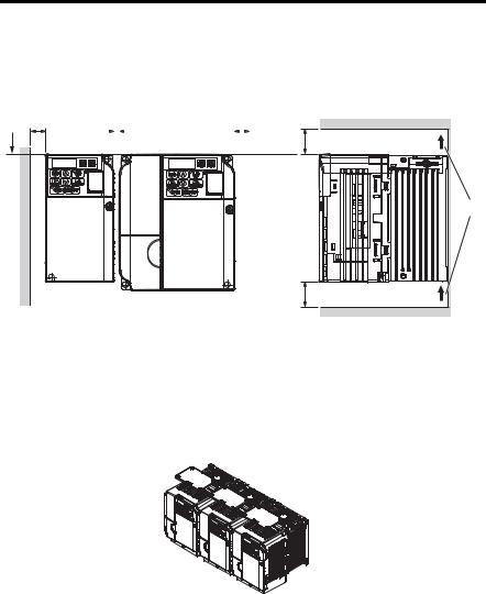
■Multiple Drive Installation
When installing multiple drives into the same enclosure panel, mount the drives according to Figure 2.2. When mounting drives with a minimum side-by-side clearance of 2 mm according to Figure 2.3, derating must be considered and parameter L8-35 must be set.
Refer to Parameter List on page 113.
A B
A
B
2 mm |
|
|
|
|
B |
|
||
|
|
|
|
|
|
|
|
|
|
|
|
|
|
|
|
|
|
|
|
|
|
|
|
|
|
|
–Line up the tops of the drives.
–30 mm minimum
|
C |
|
D |
|
C |
C |
– 100 mm minimum |
D |
– Airflow direction |
Figure 2.3 Space Between Drives (Side-by-Side Mounting)
Note: When installing drives of different sizes into the same enclosure panel, the tops of the drives should line up. Leave space between the top and bottom of stacked drives for cooling fan replacement if required. Using this method, it is possible to replace the cooling fans later.
NOTICE: When drives with IP20/NEMA Type 1 enclosures are mounted side-by-side, the top covers of all drives must be removed as shown in the figure below.
Figure 2.4 IP20/NEMA 1 Side-by-Side Mounting in Enclosure
22 |
YASKAWA ELECTRIC TOEP C710606 12B YASKAWA AC Drive V1000 Quick Start Guide |
2.1 Mechanical Installation
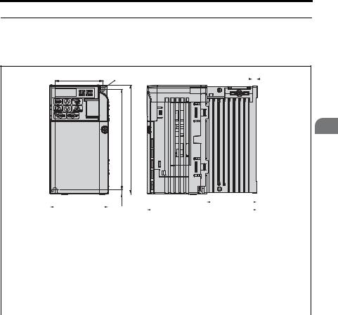
Exterior and Mounting Dimensions
■IP20/Open-Chassis Drives
Table 2.2 IP20/Open-Chassis (without an EMC filter)
W1 |
2-M4 |
t1 |
|
|
|
|
|
|
|
H
H1
|
|
W |
|
H2 |
|
|
|
|
|
|
D1 |
|
|
|
|
|
|
|
|
|
|
|
|
|
|
|
|
||||
|
|
|
|
|
|
|
D |
|
|
|
|
|
|||
|
|
|
|
|
|
|
|
|
|
|
|
|
|||
|
|
|
|
|
|
|
|
|
|
|
|
|
|
||
|
|
|
|
|
|
|
|
|
|
|
|
|
|
|
|
Voltage Class |
Drive Model |
|
|
|
|
|
Dimensions (mm) |
|
|
|
|||||
CIMR-V |
|
W1 |
|
H1 |
W |
H |
D |
t1 |
|
H2 |
D1 |
Weight |
|||
|
|
|
|
|
|||||||||||
|
|
|
|
|
|
|
|
|
|
|
|
|
|
|
(kg) |
Single-Phase |
BA0001B |
56 |
118 |
68 |
128 |
76 |
3 |
|
5 |
6.5 |
0.6 |
||||
BA0002B |
56 |
118 |
68 |
128 |
76 |
3 |
|
5 |
6.5 |
0.6 |
|||||
200 V Class |
|
||||||||||||||
|
|
|
|
|
|
|
|
|
|
|
|
|
|
||
BA0003B |
56 |
118 |
68 |
128 |
118 |
5 |
|
5 |
38.5 |
1.0 |
|||||
|
|
|
|||||||||||||
|
|
2A0001B |
56 |
118 |
68 |
128 |
76 |
3 |
|
5 |
6.5 |
0.6 |
|||
Three-Phase |
2A0002B |
56 |
118 |
68 |
128 |
76 |
3 |
|
5 |
6.5 |
0.6 |
||||
200 V Class |
2A0004B |
56 |
118 |
68 |
128 |
108 |
5 |
|
5 |
38.5 |
0.9 |
||||
|
|
2A0006B |
56 |
118 |
68 |
128 |
128 |
5 |
|
5 |
58.5 |
1.1 |
|||
Mechanical Installation
2
YASKAWA ELECTRIC TOEP C710606 12B YASKAWA AC Drive V1000 Quick Start Guide |
23 |
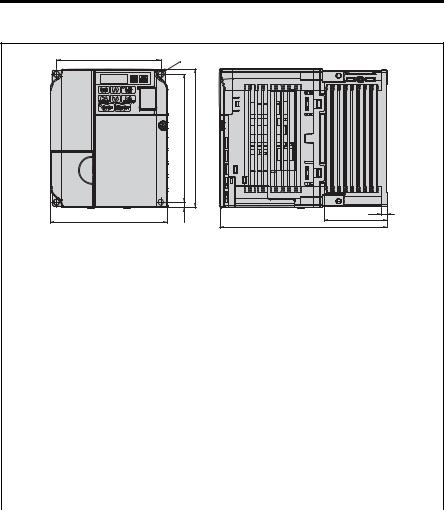
2.1 Mechanical Installation
Table 2.3 IP20/Open-Chassis (without an EMC filter)
W1
W
4-M4
H1 |
H |
H2
t1
D1
D
Voltage Class |
Drive Model |
|
|
|
Dimensions (mm) |
|
|
|
|||
CIMR-V |
W1 |
H1 |
W |
H |
D |
t1 |
|
H2 |
D1 |
Weight |
|
|
|
||||||||||
|
|
|
|
|
|
|
|
|
|
|
(kg) |
|
BA0006B |
96 |
118 |
108 |
128 |
137.5 |
5 |
|
5 |
58 |
1.7 |
Single-Phase |
BA0010B |
96 |
118 |
108 |
128 |
154 |
5 |
|
5 |
58 |
1.8 |
200 V Class |
BA0012B |
128 |
118 |
140 |
128 |
163 |
5 |
|
5 |
65 |
2.4 |
|
BA0018B |
158 |
118 |
170 |
128 |
180 |
5 |
|
5 |
65 |
3.0 |
|
2A0008B |
96 |
118 |
108 |
128 |
129 |
5 |
|
5 |
58 |
1.7 |
Three-Phase |
2A0010B |
96 |
118 |
108 |
128 |
129 |
5 |
|
5 |
58 |
1.7 |
200 V Class |
2A0012B |
96 |
118 |
108 |
128 |
137.5 |
5 |
|
5 |
58 |
1.7 |
|
2A0018B |
128 |
118 |
140 |
128 |
143 |
5 |
|
5 |
65 |
2.4 |
|
2A0020B |
128 |
118 |
140 |
128 |
143 |
5 |
|
5 |
65 |
2.4 |
|
4A0001B |
96 |
118 |
108 |
128 |
81 |
5 |
|
5 |
10 |
1.0 |
|
4A0002B |
96 |
118 |
108 |
128 |
99 |
5 |
|
5 |
28 |
1.2 |
Three-Phase |
4A0004B |
96 |
118 |
108 |
128 |
137.5 |
5 |
|
5 |
58 |
1.7 |
4A0005B |
96 |
118 |
108 |
128 |
154 |
5 |
|
5 |
58 |
1.7 |
|
400 V Class |
|
||||||||||
4A0007B |
96 |
118 |
108 |
128 |
154 |
5 |
|
5 |
58 |
1.7 |
|
|
|
||||||||||
|
4A0009B |
96 |
118 |
108 |
128 |
154 |
5 |
|
5 |
58 |
1.7 |
|
4A0011B |
128 |
118 |
140 |
128 |
143 |
5 |
|
5 |
65 |
2.4 |
24 |
YASKAWA ELECTRIC TOEP C710606 12B YASKAWA AC Drive V1000 Quick Start Guide |
2.1 Mechanical Installation
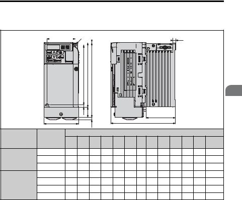
■IP20/NEMA Type 1 Drives
Table 2.4 IP20/NEMA Type 1 (without an EMC filter)
|
W1 |
|
|
2-M4 |
H6 |
|
|
|
|
|
|
|
|
|
|
|
t1 |
||||
|
|
|
|
|
|
|
|
|
|
|
|
|
|
|
|
|
|
|
|
|
|
|
|
|
|
|
|
|
|
|
|
|
|
|
|
|
|
|
|
|
|
|
|
|
|
|
|
|
|
|
|
|
|
|
|
|
|
|
|
|
|
|
|
|
|
|
|
|
|
|
|
|
|
|
|
|
|
|
|
|
|
|
|
|
|
|
|
|
|
|
|
|
|
|
|
|
|
|
|
|
|
|
|
|
|
|
|
|
|
|
|
|
|
|
|
|
|
|
|
|
|
|
|
|
|
|
|
|
|
|
|
|
|
|
|
|
|
|
|
|
|
|
|
|
|
|
|
|
|
|
|
|
|
H
H1
H2
|
|
|
H5 |
H4 |
|
|
|
|
|
|
D1 |
|
|
|
|
|
|
|
|
|
|
|
|
|
|
|
|
|
|
|
|
||
|
W |
|
|
|
H3 |
|
|
|
D |
|
|
|
|
|
|
|
|
|
|
|
|
|
|
|
|
|
|
|
|
|
|
||
Voltage Class |
Drive Model |
|
|
|
|
|
|
Dimensions (mm) |
|
|
|
|
||||
W1 |
H2 |
W |
H1 |
D |
t1 |
H5 |
D1 |
H |
H4 |
H3 |
H6 |
Weight |
||||
|
CIMR-V |
|||||||||||||||
|
|
|
|
|
|
|
|
|
|
|
|
|
|
|
(kg) |
|
Single-Phase |
BA0001F |
56 |
118 |
68 |
129.5 |
76 |
3 |
5 |
6.5 |
149.5 |
20 |
4 |
1.5 |
0.8 |
||
BA0002F |
56 |
118 |
68 |
129.5 |
76 |
3 |
5 |
6.5 |
149.5 |
20 |
4 |
1.5 |
0.8 |
|||
200 V Class |
||||||||||||||||
BA0003F |
56 |
118 |
68 |
129.5 |
118 |
5 |
5 |
39 |
149.5 |
20 |
4 |
1.5 |
1.2 |
|||
|
||||||||||||||||
|
2A0001F |
56 |
118 |
68 |
129.5 |
76 |
3 |
5 |
6.5 |
149.5 |
20 |
4 |
1.5 |
0.8 |
||
Three-Phase |
2A0002F |
56 |
118 |
68 |
129.5 |
76 |
3 |
5 |
6.5 |
149.5 |
20 |
4 |
1.5 |
0.8 |
||
200 V Class |
2A0004F |
56 |
118 |
68 |
129.5 |
108 |
5 |
5 |
39 |
149.5 |
20 |
4 |
1.5 |
1.1 |
||
|
2A0006F |
56 |
118 |
68 |
129.5 |
128 |
5 |
5 |
59 |
149.5 |
20 |
4 |
1.5 |
1.3 |
||
Mechanical Installation
2
YASKAWA ELECTRIC TOEP C710606 12B YASKAWA AC Drive V1000 Quick Start Guide |
25 |
2.1 Mechanical Installation
Table 2.5 IP20/NEMA Type 1 (without an EMC filter)
W1
W
4-M4 |
H6 |
|
H2 |
|
H1 |
H |
|
|||
|
|
|
|
|
|
|
|
H5 |
H4 |
|
|
H3
t1
D1
D
Voltage Class |
Drive Model |
|
|
|
|
|
Dimensions (mm) |
|
|
|
|
||||
W1 |
H2 |
W |
H1 |
D |
t1 |
H5 |
D1 |
H |
H4 |
H3 |
H6 |
Weight |
|||
|
CIMR-V |
||||||||||||||
|
|
|
|
|
|
|
|
|
|
|
|
|
|
(kg) |
|
|
BA0006F |
96 |
118 |
108 |
129.5 |
137.5 |
5 |
5 |
58 |
149.5 |
20 |
4 |
1.5 |
1.9 |
|
|
|
|
|
|
|
|
|
|
|
|
|
|
|
|
|
Single-Phase |
BA0010F |
96 |
118 |
108 |
129.5 |
154 |
5 |
5 |
58 |
149.5 |
20 |
4 |
1.5 |
2.0 |
|
200 V Class |
BA0012F |
128 |
118 |
140 |
133 |
163 |
5 |
5 |
65 |
153 |
20 |
4.8 |
5 |
2.6 |
|
|
BA0018F |
158 |
118 |
170 |
133 |
180 |
5 |
5 |
65 |
171 |
38 |
4.8 |
5 |
3.3 |
|
|
2A0008F |
96 |
118 |
108 |
129.5 |
129 |
5 |
5 |
58 |
149.5 |
20 |
4 |
1.5 |
1.9 |
|
Three-Phase |
2A0010F |
96 |
118 |
108 |
129.5 |
129 |
5 |
5 |
58 |
149.5 |
20 |
4 |
1.5 |
1.9 |
|
200 V Class |
2A0012F |
96 |
118 |
108 |
129.5 |
137.5 |
5 |
5 |
58 |
149.5 |
20 |
4 |
1.5 |
1.9 |
|
|
|
|
|
|
|
|
|
|
|
|
|
|
|
|
|
|
2A0018F |
128 |
118 |
140 |
133 |
143 |
5 |
5 |
65 |
153 |
20 |
4.8 |
5 |
2.6 |
|
|
2A0020F |
128 |
118 |
140 |
133 |
143 |
5 |
5 |
65 |
153 |
20 |
4.8 |
5 |
2.6 |
|
|
4A0001F |
96 |
118 |
108 |
129.5 |
81 |
5 |
5 |
10 |
149.5 |
20 |
4 |
1.5 |
1.2 |
|
|
|
|
|
|
|
|
|
|
|
|
|
|
|
|
|
|
4A0002F |
96 |
118 |
108 |
129.5 |
99 |
5 |
5 |
28 |
149.5 |
20 |
4 |
1.5 |
1.4 |
|
Three-Phase |
4A0004F |
96 |
118 |
108 |
129.5 |
137.5 |
5 |
5 |
58 |
149.5 |
20 |
4 |
1.5 |
1.9 |
|
4A0005F |
96 |
118 |
108 |
129.5 |
154 |
5 |
5 |
58 |
149.5 |
20 |
4 |
1.5 |
1.9 |
||
400 V Class |
|||||||||||||||
|
|
|
|
|
|
|
|
|
|
|
|
|
|
||
4A0007F |
96 |
118 |
108 |
129.5 |
154 |
5 |
5 |
58 |
149.5 |
20 |
4 |
1.5 |
1.9 |
||
|
|||||||||||||||
|
4A0009F |
96 |
118 |
108 |
129.5 |
154 |
5 |
5 |
58 |
149.5 |
20 |
4 |
1.5 |
1.9 |
|
|
4A0011F |
128 |
118 |
140 |
133 |
143 |
5 |
5 |
65 |
153 |
20 |
4.8 |
5 |
2.6 |
|
26 |
YASKAWA ELECTRIC TOEP C710606 12B YASKAWA AC Drive V1000 Quick Start Guide |

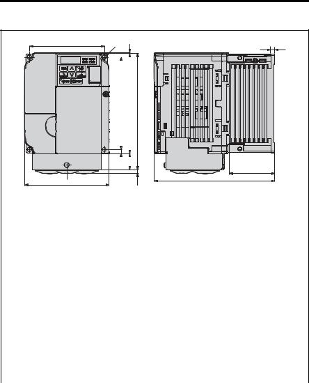
2.1 Mechanical Installation
Table 2.6 IP20/NEMA Type 1 (without an EMC filter)
W1 4-d
|
H6 |
|
Installation |
H2 |
H1 |
H |
Mechanical |
2
|
|
|
|
H5 |
H4 |
H3 |
|
|
|
|
|
t1 |
|
|
|
|
|
|
W |
|
|
|
|
|
|
|
D1 |
|
|
|
|
||||
|
|
|
|
|
|
|
|
|
|
|
|
|
|
|
|||
|
|
|
|
|
|
|
|
|
|
|
D |
|
|
|
|
|
|
Voltage Class |
Drive Model |
|
|
|
|
|
|
Dimensions (mm) |
|
|
|
|
|
||||
W1 |
H2 |
W |
H1 |
D |
t1 |
H5 |
D1 |
H |
H4 |
H3 |
H6 |
d |
Weight |
||||
|
CIMR-V |
||||||||||||||||
|
|
|
|
|
|
|
|
|
|
|
|
|
|
|
|
(kg) |
|
|
2A0030B |
122 |
248 |
140 |
234 |
140 |
5 |
13 |
55 |
254 |
13 |
6 |
1.5 |
M5 |
3.8 |
||
Three-Phase |
2A0040B |
122 |
248 |
140 |
234 |
140 |
5 |
13 |
55 |
254 |
13 |
6 |
1.5 |
M5 |
3.8 |
||
200 V Class |
2A0056B |
160 |
284 |
180 |
270 |
163 |
5 |
13 |
75 |
290 |
15 |
6 |
1.5 |
M5 |
5.5 |
||
|
2A0069B |
192 |
336 |
220 |
320 |
187 |
5 |
22 |
78 |
350 |
15 |
7 |
1.5 |
M6 |
9.2 |
||
|
4A0018B |
122 |
248 |
140 |
234 |
140 |
5 |
13 |
55 |
254 |
13 |
6 |
1.5 |
M5 |
3.8 |
||
Three-Phase |
4A0023B |
122 |
248 |
140 |
234 |
140 |
5 |
13 |
55 |
254 |
13 |
6 |
1.5 |
M5 |
3.8 |
||
400 V Class |
4A0031B |
160 |
284 |
180 |
270 |
143 |
5 |
13 |
55 |
290 |
15 |
6 |
1.5 |
M5 |
5.2 |
||
|
4A0038B |
160 |
284 |
180 |
270 |
163 |
5 |
13 |
75 |
290 |
13 |
6 |
1.5 |
M5 |
5.5 |
||
YASKAWA ELECTRIC TOEP C710606 12B YASKAWA AC Drive V1000 Quick Start Guide |
27 |

2.1 Mechanical Installation
28 |
YASKAWA ELECTRIC TOEP C710606 12B YASKAWA AC Drive V1000 Quick Start Guide |

3
Electrical
Installation
This chapter explains proper procedures for wiring the control circuit terminals, motor and power supply.
3.1 STANDARD CONNECTION DIAGRAM. . . . . . . . . . . . . . .30 3.2 MAIN CIRCUIT WIRING . . . . . . . . . . . . . . . . . . . . . . . . . . .33 3.3 I/O CONNECTIONS . . . . . . . . . . . . . . . . . . . . . . . . . . . . . .45 3.4 MAIN FREQUENCY REFERENCE . . . . . . . . . . . . . . . . . .47 3.5 WIRING CHECKLIST . . . . . . . . . . . . . . . . . . . . . . . . . . . . .49
YASKAWA ELECTRIC TOEP C710606 12B YASKAWA AC Drive V1000 Quick Start Guide |
29 |

3.1 Standard Connection Diagram
3.1Standard Connection Diagram
Connect the drive and peripheral devices as shown in Figure 3.1. It is possible to run the drive via the digital operator without connecting digital I/O wiring. This section does not discuss drive operation; Refer to Start-Up Programming & Operation on page 51 for instructions on operating the drive.
NOTICE: Inadequate branch short circuit protection could result in damage to the drive. Install adequate branch circuit short circuit protection per applicable codes. The drive is suitable for circuits capable of delivering not more than 30,000 RMS symmetrical amperes, 240 Vac maximum (200 V Class) and 480 Vac maximum (400 V Class).
NOTICE: When the input voltage is 480 V or higher or the wiring distance is greater than 100 meters, pay special attention to the motor insulation voltage or use an inverter duty motor. Failure to comply could lead to motor insulation breakdown.
NOTICE: Do not connect the AC control circuit ground to the drive enclosure. Improper drive grounding can cause the control circuit to malfunction.
NOTICE: The minimum load for the multi-function relay output MA-MB-MC is 10 mA (reference value). If a circuit requires less than 10 mA, connect it to a photocoupler output (P1, P2, PC). Improper application of peripheral devices could result in damage to the photocoupler output of the drive.
30 |
YASKAWA ELECTRIC TOEP C710606 12B YASKAWA AC Drive V1000 Quick Start Guide |
Loading...