


 Loading...
A1000 6-Phase/12-Pulse Input
Flange Mount and Non-Flange Mount
Installation Manual
Type: CIMR-AU4T 
 A and CIMR-AU4T
 U
U
Models: 400 V Class: 30 to 355 kW (40 to 550 HP ND)
To properly use the product, read this manual thoroughly and retain for easy reference, inspection, and maintenance. Ensure the end user receives this manual.
MANUAL NO. TOEP YAIA1U 02A
Copyright © 2015 YASKAWA AMERICA, INC. All rights reserved.
No part of this publication may be reproduced, stored in a retrieval system, or transmitted, in any form or by any means, mechanical, electronic, photocopying, recording, or otherwise, without the prior written permission of Yaskawa. No patent liability is assumed with respect to the use of the information contained herein. Moreover, because Yaskawa is constantly striving to improve its high-quality products, the information contained in this manual is subject to change without notice. Every precaution has been taken in the preparation of this manual. Yaskawa assumes no responsibility for errors or omissions. Neither is any liability assumed for damages resulting from the use of the information contained in this publication.

Preface
1 PREFACE |
.................................................................................................................4 |
YASKAWA TOEP YAIA1U 02A YASKAWA AC Drive – A1000 6-Phase/12-Pulse Input Installation Manual |
3 |
1Preface
1Preface
Yaskawa manufactures products used as components in a wide variety of industrial systems and equipment. The selection and application of Yaskawa products remain the responsibility of the equipment manufacturer or end user. Yaskawa accepts no responsibility for the way its products are incorporated into the final system design. Under no circumstances should any Yaskawa product be incorporated into any product or design as the exclusive or sole safety control. Without exception, all controls should be designed to detect faults dynamically and fail safely under all circumstances. All systems or equipment designed to incorporate a product manufactured by Yaskawa must be supplied to the end user with appropriate warnings and instructions as to the safe use and operation of that part. Any warnings provided by Yaskawa must be promptly provided to the end user. Yaskawa offers an express warranty only as to the quality of its products in conforming to standards and specifications published in the Yaskawa manual. NO OTHER WARRANTY, EXPRESS OR IMPLIED, IS OFFERED. Yaskawa assumes no liability for any personal injury, property damage, losses, or claims arising from misapplication of its products.
This manual is designed to ensure correct and suitable application of A1000-Series Drives with 6-Phase/12-Pulse rectification. Read this manual before attempting to install or operate a drive and keep it in a safe, convenient location for future reference. Be sure you understand all precautions and safety information before attempting application.
Use this manual as the primary reference to install and wire A1000 drives with 6-Phase/12-Pulse rectification together with the A1000 Quick Start Guide and Technical Manual.
u Product Overview
The A1000 6-Phase/12-Pulse drive design matches an isolation transformer with a tuned input reactor to provide a phase shift that reduces harmonic distortion for cleaner power.
u Applicable Documentation
The following manuals are available for A1000 series drives:
A1000 Series AC Drive 6-Phase/12-Pulse Input Installation Manual (TOEPYAIA1U02)
This guide is packaged together with the product and contains information required to install and wire the drive with 6-Phase/12-Pulse rectification. This manual is available for download on our documentation website, www.yaskawa.com.
A1000 Series AC Drive Quick Start Guide (TOEPC71061641)
This guide contains basic information required to install and wire the 3-Phase/6-Pulse drive and gives an overview of fault diagnostics, maintenance, and parameter settings for 3-Phase/6-Pulse and 6-Phase/12- Pulse drives. The purpose of this guide is to prepare the drive for a trial run with an application and for basic operation. This manual is available for download on our documentation website, www.yaskawa.com.
A1000 Series AC Drive Technical Manual (SIEPC71061641)
This manual provides detailed information on 3-Phase/6-Pulse and 6-Phase/12-Pulse parameter settings, drive functions, and MEMOBUS/Modbus specifications. Use this manual to expand drive functionality and to take advantage of higher performance features. This manual is available for download on our documentation website, www.yaskawa.com.
u Supplemental Safety Information
General Precautions
•The diagrams in this manual may be indicated without covers or safety shields to show details. Replace the covers or shields before operating the drive and run the drive according to the instructions described in this manual.
•Any illustrations, photographs, or examples used in this manual are provided as examples only and may not apply to all products to which this manual is applicable.
•The products and specifications described in this manual or the content and presentation of the manual may be changed without notice to improve the product and/or the manual.
•When ordering a new copy of the manual due to damage or loss, contact your Yaskawa representative or the nearest Yaskawa sales office and provide the manual number shown on the front cover.
•If nameplate becomes worn or damaged, order a replacement from your Yaskawa representative or the nearest Yaskawa sales office.
 WARNING
Read and understand this manual before installing, operating or servicing this drive. The drive must be installed according to this manual and local codes.
4 |
YASKAWA TOEP YAIA1U 02A YASKAWA AC Drive – A1000 6-Phase/12-Pulse Input Installation Manual |

1 Preface
 WARNING
The following conventions are used to indicate safety messages in this manual. Failure to heed these messages could result in serious or fatal injury or damage to the products or to related equipment and systems.
 DANGER
Indicates a hazardous situation, which, if not avoided, will result in death or serious injury.
 WARNING
Indicates a hazardous situation, which, if not avoided, could result in death or serious injury.
WARNING! may also be indicated by a bold key word embedded in the text followed by an italicized safety message.
 CAUTION
Indicates a hazardous situation, which, if not avoided, could result in minor or moderate injury.
CAUTION! may also be indicated by a bold key word embedded in the text followed by an italicized safety message.
NOTICE
Indicates a property damage message.
NOTICE: may also be indicated by a bold key word embedded in the text followed by an italicized safety message.
u Safety Messages
 DANGER
Heed the safety messages in this manual.
Failure to comply will result in death or serious injury.
The operating company is responsible for any injuries or equipment damage resulting from failure to heed the warnings in this manual.
Electrical Shock Hazard
Before servicing, disconnect all power to the equipment.
The capacitor for the control power supply remains charged even after the power supply is turned off. The charge indicator LED will extinguish when the control power supply voltage is below 50 Vdc. To prevent electric shock, wait for at least the time specified on the warning label, once all indicators are OFF, measure for unsafe voltages to confirm the drive is safe prior to servicing.
Failure to comply will result in death or serious injury.
 WARNING
Sudden Movement Hazard
System may start unexpectedly upon application of power, resulting in death or serious injury.
Clear all personnel from the drive, motor and machine area before applying power. Secure covers, couplings, shaft keys and machine loads before applying power to the drive.
YASKAWA TOEP YAIA1U 02A YASKAWA AC Drive – A1000 6-Phase/12-Pulse Input Installation Manual |
5 |

1 Preface
 WARNING
Electrical Shock Hazard
Do not attempt to modify or alter the drive in any way not explained in this manual.
Failure to comply could result in death or serious injury.
Yaskawa is not responsible for any modification of the product made by the user. This product must not be modified.
Do not allow unqualified personnel to use equipment.
Failure to comply could result in death or serious injury.
Installation, maintenance, inspection, and service must be performed only by authorized personnel familiar with installation, adjustment and maintenance of AC drives.
Do not remove covers or touch circuit boards while the power is on.
Failure to comply could result in death or serious injury.
Make sure the protective earthing conductor complies with technical standards and local safety regulations.
Because the leakage current exceeds 3.5 mA in models 4o0302 and larger, IEC/EN 61800-5-1 states that either the power supply must be automatically disconnected in case of discontinuity of the protective earthing conductor or a protective earthing conductor with a cross-section of at least 10 mm2 (Cu) or 16 mm2 (Al) must be used. Failure to comply may result in death or serious injury.
Always use appropriate equipment for Ground Fault Circuit Interrupters (GFCIs).
The drive can cause a residual current with a DC component in the protective earthing conductor. Where a residual current operated protective or monitoring device is used for protection in case of direct or indirect contact, always use a type B GFCI according to IEC/EN 60755.
Fire Hazard
Do not use an improper voltage source.
Failure to comply could result in death or serious injury by fire.
Verify that the rated voltage of the drive matches the voltage of the incoming power supply before applying power.
Install adequate branch circuit protection according to applicable local codes and this Installation Manual. Failure to comply could result in fire and damage to the drive or injury to personnel.
The device is suitable for use on a circuit capable of delivering not more than 100,000 RMS symmetrical amperes, 480 Vac maximum (400 V class), when protected by branch circuit protection devices specified in this manual.
Crush Hazard
Do not use this drive in lifting applications without installing external safety circuitry to prevent accidental dropping of the load.
The drive does not possess built-in load drop protection for lifting applications.
Failure to comply could result in death or serious injury from falling loads.
Install electrical and/or mechanical safety circuit mechanisms independent of drive circuitry.
 CAUTION
Crush Hazard
Do not carry the drive by the front cover.
Failure to comply may result in minor or moderate injury from the main body of the drive falling.
6 |
YASKAWA TOEP YAIA1U 02A YASKAWA AC Drive – A1000 6-Phase/12-Pulse Input Installation Manual |
1 Preface
NOTICE
Observe proper electrostatic discharge procedures (ESD) when handling the drive and circuit boards. Failure to comply may result in ESD damage to the drive circuitry.
Do not perform a withstand voltage test on any part of the drive.
Failure to comply could result in damage to the sensitive devices within the drive.
Do not operate damaged equipment.
Failure to comply could result in further damage to the equipment. Do not connect or operate any equipment with visible damage or missing parts.
If a fuse is blown or a Ground Fault Circuit Interrupter (GFCI) is tripped, check the wiring and the selection of the peripheral devices.
Contact your supplier if the cause cannot be identified after checking the above.
Do not restart the drive immediately operate the peripheral devices if a fuse is blown or a GFCI is tripped.
Check the wiring and the selection of peripheral devices to identify the cause. Contact your supplier before restarting the drive or the peripheral devices if the cause cannot be identified.
Do not expose the drive to halogen group disinfectants.
Failure to comply may cause damage to the electrical components in the drive.
Do not pack the drive in wooden materials that have been fumigated or sterilized. Do not sterilize the entire package after the product is packed.
n General Application Precautions
Selection
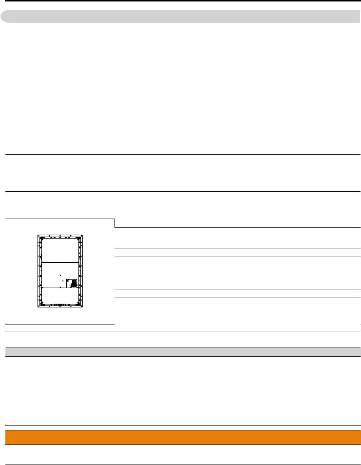
Installing a Transformer
Install a 6-Phase/12-Pulse isolation transformer with each of the output windings phase shifted by 30 electrical degrees or install a Hybrid 6-Phase topology on the power supply.
Installing a Reactor
Use an AC reactor or DC link choke in the following situations:
•to suppress harmonic current.
•to smooth peak current that results from capacitor switching.
•when the power supply is above 600 kVA.
•when the drive is running from a power supply system with thyristor converters.
Power Supply
Capacity (kVA)
4000 |
Power supply harmonics |
|
|
reactor required |
|
600 |
Reactor |
|
|
|
|
|
unnecessary |
|
0 |
60 |
400 |
|
Drive Capacity (kVA)
Figure Installing a Reactor
Inspection and Maintenance
WARNING! Electrical Shock Hazard. Capacitors for the control power supply do not immediately discharge after shutting off the power. Wait for at least the amount of time specified on the drive before touching any components after shutting off the power. Failure to comply may cause injury to personnel from electrical shock.
YASKAWA TOEP YAIA1U 02A YASKAWA AC Drive – A1000 6-Phase/12-Pulse Input Installation Manual |
7 |
1 Preface
WARNING! Electrical Shock Hazard. When a drive is running a PM motor, voltage continues to be generated at the motor terminals after the drive is shut off while the motor coasts to stop. Take the precautions described below to prevent shock and injury:
∙In applications where the machine can still rotate after the drive has fully stopped a load, install a switch to the drive output side to disconnect the motor and the drive.
∙Do not allow an external force to rotate the motor beyond the maximum allowable speed or to rotate the motor when the drive has been shut off.
∙Wait for at least the time specified on the warning label after opening the load switch on the output side before inspecting the drive or performing any maintenance.
∙Do not open and close the load switch while the motor is running.
∙If the motor is coasting, make sure the power to the drive is turned on and the drive output has completely stopped before closing the load switch.
WARNING! Burn Hazard. Because the heatsink can get very hot during operation, take proper precautions to prevent burns. When replacing the cooling fan, shut off the power and wait at least 15 minutes to be sure that the heatsink has cooled down. Failure to comply may cause burn injury to personnel.
Wiring
All wire ends should use ring terminals for UL/cUL compliance. Use only the tools recommended by the terminal manufacturer for crimping.
Transporting the Drive
NOTICE: Never steam clean the drive. During transport, keep the drive from coming into contact with salts, fluorine, bromine, phthalate ester, and other such harmful chemicals.
u Drive Label Warning Example
Always heed the warning information listed in Figure .
 WARNING
Risk of electric shock.
● Read manual before installing. ● Wait 5 minutes for capacitor
discharge after disconnecting power supply.
● To conform to requirements, make sure to ground the supply neutral for 400V class.
●After opening the manual switch between the drive and motor, please wait 5 minutes before inspecting, performing maintenance or wiring the drive.
Hot surfaces
●Top and Side surfaces may become hot. Do not touch.
Figure Warning Information Example
u Warranty Information n Restrictions
The drive is not designed or manufactured for use in devices or systems that may directly affect or threaten human lives or health.
Customers who intend to use the product described in this manual for devices or systems relating to transportation, health care, space aviation, atomic power, electric power, or in underwater applications must first contact their Yaskawa representatives or the nearest Yaskawa sales office.
WARNING! Injury to Personnel. This product has been manufactured under strict quality-control guidelines. However, if this product is to be installed in any location where failure of this product could involve or result in a life-and-death situation or loss of human life or in a facility where failure may cause a serious accident or physical injury, safety devices must be installed to minimize the likelihood of any accident.
8 |
YASKAWA TOEP YAIA1U 02A YASKAWA AC Drive – A1000 6-Phase/12-Pulse Input Installation Manual |

Installation Manual
1 |
RECEIVING............................................................................................................ |
10 |
2 |
MECHANICAL INSTALLATION............................................................................. |
13 |
3 |
ELECTRICAL INSTALLATION.............................................................................. |
15 |
4 |
START-UP PROGRAMMING & OPERATION....................................................... |
26 |
5 |
TROUBLESHOOTING............................................................................................ |
27 |
6 |
DRIVE OPTIONS AND PERIPHERAL DEVICES.................................................. |
29 |
7 |
PERIODIC INSPECTION & MAINTENANCE......................................................... |
35 |
8 |
SPECIFICATIONS.................................................................................................. |
38 |
9 |
PARAMETER TABLE............................................................................................ |
77 |
10 |
STANDARDS COMPLIANCE................................................................................ |
81 |
YASKAWA TOEP YAIA1U 02A YASKAWA AC Drive – A1000 6-Phase/12-Pulse Input Installation Manual |
9 |
1Receiving
1Receiving
u Model Number and Nameplate Check
Please perform the following tasks after receiving the drive:
•Inspect the drive for damage.
If the drive appears damaged upon receipt, contact the shipper immediately.
•Verify receipt of the correct model by checking the information on the nameplate.
•If you have received the wrong model or the drive does not function properly, contact your supplier.
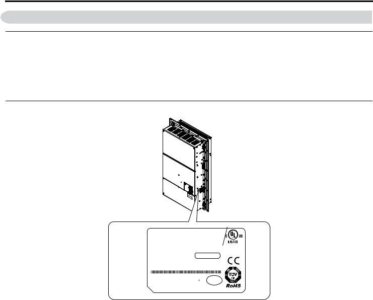
u Nameplate
A
I |
|
|
MODEL |
: CIMR-AU4T0675UAA REV:A |
|
|
|
|
|
|
|
|
|
||||||||
|
|
|
|
|
|
|
|
|
|
||||||||||||
H |
|
|
|
C/C CIMR-AU4T0675UAA |
|
|
|
|
|
|
|
|
|
|
|||||||
|
|
INPUT |
: AC6PH(12P) 380-480V 50/60Hz 603A/511A |
IND.CONT.EQ. |
|
|
|||||||||||||||
|
|
|
|||||||||||||||||||
G |
|
|
|
OUTPUT : AC3PH 0-480V 0-400Hz 675A/605A |
|
|
|||||||||||||||
|
|
|
7J48 |
|
B |
||||||||||||||||
F |
|
|
|
MASS |
: 220kg |
PRG : 1010 |
|
|
|
||||||||||||
|
|
|
|
|
|
|
|
|
|
|
|
|
|||||||||
|
|
|
O / N |
: |
|
|
|
|
|
|
|
|
|
|
|
|
|
|
|||
|
|
|
|
|
|
|
|
|
|
|
|
|
|
|
|
|
|||||
E |
|
|
|
S / N |
: |
|
|
PASS |
|
|
|
|
|
|
|
|
|
||||
|
|
|
|
|
|
|
|
|
|
|
|
|
|||||||||
D |
|
|
|
FILE NO |
: E131457 |
IP00 |
|
|
|
|
|
|
|
|
|
||||||
|
|
|
|
|
|
|
|
|
|
|
|
|
|||||||||
|
|
|
|
|
|
|
|
|
|
|
|
|
|
|
|
|
|||||
|
|
|
|
|
YASKAWA ELECTRIC CORPORATION |
MADE IN JAPAN |
|
|
|
|
|
|
|
|
|
C |
|||||
|
|
|
|
|
|
2-1 Kurosaki-shiroishi, Yahatanishi-ku, Kitakyushu 806-0004 Japan |
|
|
|||||||||||||
|
|
|
|
|
|
|
|
|
|||||||||||||
A – Normal Duty / Heavy Duty Amps B – Software version
C – Address <1>
D – Enclosure type E – Serial number
F – Lot number
G – Output specifications H – Input specifications
I – AC drive model
Figure 1 Nameplate Information Example
<1> The address of the head office of Yaskawa Electric Corporation (responsible for product liability) is shown on the nameplate.
10 |
YASKAWA TOEP YAIA1U 02A YASKAWA AC Drive – A1000 6-Phase/12-Pulse Input Installation Manual |
1 Receiving
|
|
CIMR |
|
- A U 4 |
T |
0675 |
|
U |
|
|
A |
|
A |
|||||||||||||||||||||||
|
|
|
|
|
|
|
|
|
|
|
|
|
|
|
|
|
|
|
|
|
|
|
|
|
|
|
|
|
|
|
|
|
|
|
|
|
|
|
|
|
|
|
|
|
A1000 |
|
|
|
|
|
|
|
|
|
|
|
|
|
|
|
|
|
|
|
|
Design |
|||||||
|
|
|
Drive |
|
Series |
|
|
|
|
|
|
|
|
|
|
|
|
|
|
|
|
|
|
|
|
Revision |
||||||||||
|
|
|
|
|
|
|
|
|
|
|
|
|
|
|
|
|
|
|
|
|
|
|
|
|
|
|
|
|
|
|
|
|
Order |
|||
|
|
|
|
|
|
|
|
|
|
|
|
|
|
|
|
|
|
|
|
|
|
|
|
|
|
|
|
|
|
|
|
|
|
|
|
|
Letter |
Region |
|
|
|
No. |
Voltage Class |
|
Customized |
|
|
|
Letter |
Enclosure |
|
Letter |
Environmental |
||||||||||||||||||||
Code |
|
|
|
4 |
380-480 Vac |
|
Specification |
|
|
|
Type |
|
Specification <2> |
|||||||||||||||||||||||
|
|
|
|
|
|
|
|
|
|
|
|
|
||||||||||||||||||||||||
U |
USA |
|
|
|
|
|
|
|
|
|
|
|
6-Phase/ |
|
|
|
|
|
|
A |
Open Type |
|
|
A |
Standard |
|||||||||||
|
|
|
|
|
|
|
|
|
|
|
|
|
|
|
|
|
|
|
||||||||||||||||||
|
|
|
|
|
|
|
|
|
|
|
|
|
|
12-Pulse Input |
|
|
|
|
(Non-Flange) |
|
|
|
|
|
|
|
|
|||||||||
|
|
|
|
|
|
|
|
|
|
|
|
|
|
|
|
|
|
|
|
|
|
|
|
|
|
|
|
|
|
|
|
|
|
|
|
|
|
|
|
|
|
|
|
|
|
|
|
|
|
|
|
|
|
|
|
|
|
|
|
|
U |
Flange Type |
|
|
|
|
|
|
|
|
|||
|
|
|
|
|
|
|
|
|
|
|
|
|
|
|
|
|
|
|
|
|
|
|
|
<1> |
|
|
|
|
|
|
|
|
|
|||
|
|
|
|
|
|
|
|
|
|
|
|
|
|
|
|
|
|
|
|
|
|
|
|
|
|
|
|
|
|
|
|
|
|
|||
|
|
|
|
|
|
|
|
|
|
|
|
|
|
|
|
|
|
|
|
|
|
|
|
|
|
|
|
|
|
|
|
|
|
|
|
|
Refer to the tables below
<1> Provides method of mounting drive with backside (heatsink) external to enclosure with NEMA 12 integrity.
<2> Drives with these specifications do not guarantee complete protection for the environmental conditions indicated. n 6-Phase/12-Pulse 400 V Class Rated Output
Table 1 Model Number and Specifications (400 V Class)
|
Normal Duty (ND) |
|
|
Heavy Duty (HD) |
|
|||
|
C6-01 = 1 |
|
|
C6-01 = 0 |
|
|||
Drive Model |
Max. Motor Capacity |
Rated Output |
Drive Model |
Max. Motor Capacity |
Rated Output |
|||
kW (HP) |
Current A |
kW (HP) |
Current A |
|||||
|
|
|||||||
4T0058o |
30 |
(40) |
58 |
4T0058o |
22 (25-30) |
45 |
||
4T0072o |
37 |
(50) |
72 |
4T0072o |
30 |
(40) |
60 |
|
4T0088o |
45 |
(60) |
88 |
4T0088o |
37 (50-60) |
75 |
||
4T0103o |
55 |
(75) |
103 |
4T0103o |
45 (50-60) |
91 |
||
4T0139o |
75 (100) |
139 |
4T0139o |
55 |
(75) |
112 |
||
4T0165o |
90 (125) |
165 |
4T0165o |
75 (100) |
150 |
|||
4T0208o |
110 |
(150) |
208 |
4T0208o |
90 (125-150) |
180 |
||
4T0250o |
132 |
(200) |
250 |
4T0250o |
110 |
(150) |
216 |
|
4T0296o |
160 |
(250) |
296 |
4T0296o |
132 |
(200) |
260 |
|
4T0362o |
185 |
(300) |
362 |
4T0362o |
160 |
(250) |
304 |
|
4T0414o |
220 |
(350) |
414 |
4T0414o |
185 |
(300) |
370 |
|
4T0515o |
250 (400-450) |
515 |
4T0515o |
220 |
(350) |
450 |
||
4T0675o |
355 (500-550) |
675 |
4T0675o |
315 |
605 |
|||
(400-450-500) |
||||||||
|
|
|
|
|
|
|||
YASKAWA TOEP YAIA1U 02A YASKAWA AC Drive – A1000 6-Phase/12-Pulse Input Installation Manual |
11 |
1 Receiving
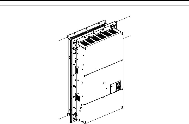
u 6-Phase/12-Pulse Component Names
A
B
D
C 


D |
|
A – Installation hole |
C – Mounting flange <1> |
B – 6-Phase/12-Pulse Drive |
D – Shipping package attachment (to |
be removed before installation) Figure 2 Flange Type Enclosure Example (Models 4TooooU)
<1> Provides method of mounting drive with backside (heatsink) external to enclosure with NEMA 12 integrity. 4TooooU models only.
NOTICE: Remove the shipping package attachments before installing. The shipping package attachments will interfere with the cutting of the panel when installing the drive.
12 |
YASKAWA TOEP YAIA1U 02A YASKAWA AC Drive – A1000 6-Phase/12-Pulse Input Installation Manual |

2 Mechanical Installation
2Mechanical Installation
This section outlines specifications, procedures, and the environment for proper mechanical installation of the drive.
u Installation Environment
Install the drive in an environment matching the specifications in Table 2 to help prolong the optimum performance life of the drive.
|
|
Table 2 Installation Environment |
|
Environment |
|
Conditions |
|
Installation Area |
Indoors |
||
|
Flange Type Enclosure: -10 °C to +40 °C (14 °F to 104 °F) |
||
|
Non-Flange Type Enclosure: -10 °C to +50 °C (14 °F to 122 °F) |
||
Ambient Temperature |
Drive reliability improves in environments without wide temperature fluctuations. |
||
When using the drive in an enclosure panel, install a cooling fan or air conditioner in the area to ensure that the air |
|||
|
|||
|
temperature inside the enclosure does not exceed the specified levels. |
||
|
Do not allow ice to develop on the drive. |
||
Humidity |
95% RH or less and free of condensation |
||
Storage Temperature |
-20 °C to +60 °C |
||
|
Install the drive in an area free from: |
||
|
• oil mist and dust |
||
|
• metal shavings, oil, water, or other foreign materials |
||
|
• |
radioactive materials |
|
Surrounding Area |
• combustible materials (e.g., wood) |
||
|
• harmful gases and liquids |
||
|
• |
excessive vibration |
|
|
• |
chlorides |
|
|
• |
direct sunlight. |
|
Altitude |
Up to 1000 m without derating, up to 3000 m with output current and voltage derating. |
||
Vibration |
10 Hz to 20 Hz at 9.8 m/s2 |
||
20 Hz to 55 Hz at 5.9 m/s2 (Models 4T0058o to 4T0165o) or 2.0 m/s2 (Models 4T0208o to 4T0675o) |
|||
|
|||
Orientation |
Install the drive vertically to maintain maximum cooling effects. |
||
NOTICE: Avoid placing drive peripheral devices, transformers, or other electronics near the drive as the noise created can lead to erroneous operation. If such devices must be used in close proximity to the drive, take proper steps to shield the drive from noise.
NOTICE: Damage to Equipment. Drive heatsink air outlet temperature may be over 80 °C. Do not install components above the air outlet that may be damaged by 80 °C air temperature.
NOTICE: Damage to Equipment. Prevent foreign matter such as metal shavings and wire clippings from falling into the drive during installation. Failure to comply could result in damage to the drive. Place a temporary cover over the top of the drive during installation. Remove the temporary cover before drive start-up, as the cover will reduce ventilation and cause the drive to overheat.
YASKAWA TOEP YAIA1U 02A YASKAWA AC Drive – A1000 6-Phase/12-Pulse Input Installation Manual |
13 |

2 Mechanical Installation
u Removing the Shipping Package Attachments
Remove the shipping package attachments before installation.
Note: The number of screws varies in accordance with the drive model.
Top Side |
Bottom Side |
Shipping Package
Attachment


 Screws
Figure 3 Removing the Shipping Package Attachments
Shipping Package
Attachment
Screws
u Exterior and Mounting Dimensions
Refer to External Mounting and Panel Cutout Dimensions on page 44 for 6-phase/12-pulse exterior and mounting dimensions.
u Weights
Table 3 Drive Weights
Drive |
4T0058o |
4T0072o |
4T0088o |
4T0103o |
4T0139o |
4T0165o |
4T0208o |
4T0250o |
4T0296o |
4T0362o |
4T0414o |
4T0515o |
4T0675o |
|
Model |
||||||||||||||
|
|
|
|
|
|
|
|
|
|
|
|
|
||
Drive |
21 (46.2) |
24 (52.8) |
35 (77.0) |
35 (77.0) |
39 (85.8) |
40 (88.2) |
78 (172) |
90 (198) |
95 (209) |
97 (214) |
127 (280) |
210 (463) |
215 (474) |
|
Weight |
||||||||||||||
kg (lb) |
|
|
|
|
|
|
|
|
|
|
|
|
|
14 |
YASKAWA TOEP YAIA1U 02A YASKAWA AC Drive – A1000 6-Phase/12-Pulse Input Installation Manual |

3 Electrical Installation
3Electrical Installation
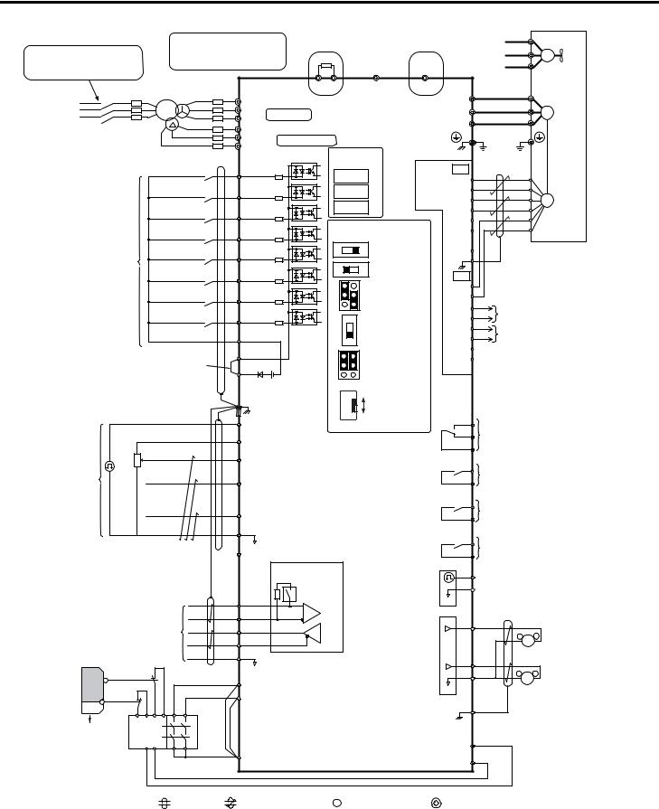
u Standard Connection Diagram
Connect the drive and peripheral devices as shown in Figure 4. It is possible to set and run the drive via the digital operator without connecting digital I/O wiring.
WARNING! Fire Hazard - Drive Short-Circuit Current Rating. Install adequate branch circuit protection according to applicable local codes and this manual. Failure to comply could result in fire and damage to the drive or injury to personnel. The device is suitable for use on a circuit capable of delivering not more than 100,000 RMS symmetrical amperes, 480 Vac maximum (400 V class), when protected by branch circuit protection devices specified in this manual.
NOTICE: Route motor leads U/T1, V/T2, and W/T3 separate from all other leads to reduce possible interference related issues. Failure to comply may result in abnormal operation of drive and nearby equipment.
NOTICE: Equipment Hazard. Standard motors used with PWM drives may experience winding failures due to surge voltages when input line voltage is greater than 480 V or motor wire distance is greater than 100 meters. Select a motor design with insulation tolerant of surge voltages, such as drive-rated motor for use with PWM drives. Failure to comply could lead to motor winding failure.
Note: The minimum load for the relay outputs M1-M2, M3-M4, M5-M6, and MA-MB-MC is 10 mA.
YASKAWA TOEP YAIA1U 02A YASKAWA AC Drive – A1000 6-Phase/12-Pulse Input Installation Manual |
15 |
3 Electrical Installation
|
|
|
|
|
|
Models 4T0058 and 4T0072 |
Models 4T0088 to 4T0675 |
|
<15> |
|
|||||
|
|
|
Terminals B1, B2, -, and +3, B1 |
Dynamic braking resistor |
CDBR dynamic braking unit |
|
|
||||||||
|
|
|
FU |
|
|
||||||||||
|
|
|
(option) <1> <2> |
|
|
(option) <1> <2> |
|
|
|
||||||
Wiring sequence should shut off |
are for power option connections. |
|
|
|
|
|
|||||||||
Never connect power supply lines |
|
|
|
|
|
|
|
FV |
|
M |
|||||
power to the drive when a fault |
to these terminals |
|
|
|
|
|
|
|
|
|
FW |
|
Cooling fan |
||
output is triggered. |
|
|
|
|
|
|
|
|
|
|
|
||||
|
|
|
|
|
|
|
|
|
|
|
|
|
|
||
Three-Phase |
Main |
<16> |
<17> |
|
|
|
B1 B2 |
|
- |
+3 |
|
|
U |
|
|
Switch |
BCP |
U1 Fuse |
R/L1 |
|
|
|
|
|
|
U/T1 |
|
|
|||
Power Supply |
R |
|
V1 |
|
|
|
|
|
|
|
V |
|
|||
380 to 480 V |
S |
|
S/L2 |
Main Circuit |
|
|
|
|
V/T2 |
|
M |
||||
T |
|
W1 |
T/L3 |
Drive |
|
|
W |
||||||||
50/60 Hz |
|
U2 |
|
|
|
W/T3 |
|
|
|||||||
|
|
|
|
|
|
|
|
|
|||||||
|
|
R1/L11 |
|
|
|
|
|
|
|
|
|
||||
|
|
|
|
|
|
|
|
|
|
|
|
|
|
||
|
|
|
V2 |
S1/L21 |
|
Control Circuit |
<3> |
|
|
|
|
|
|
|
|
|
|
|
W2 |
T1/L31 |
|
|
|
|
|
|
|
|
|||
|
|
|
|
|
|
|
Option board |
|
Ground |
|
|
||||
|
|
|
|
|
|
|
|
|
|
|
|||||
|
|
|
Forward Run / Stop |
S1 |
|
|
|
connectors |
|
TB1 |
|
|
|
||
|
|
|
|
|
|
CN5-C |
|
PG- X3 |
|
|
|
||||
|
|
|
|
|
|
|
|
|
|
|
(option) |
A+ |
|
|
|
|
|
|
|
S2 |
|
|
|
CN5-B |
|
A- |
|
|
|
||
|
|
|
Reverse Run / Stop |
|
|
|
|
<6> |
|
|
PG |
||||
|
|
|
|
|
|
|
|
CN5-A |
|
|
B+ |
|
|
||
|
|
|
External fault |
S3 |
|
|
|
|
|
B- |
|
|
|
||
|
|
|
|
|
|
|
|
|
|
Z+ |
|
|
|
||
|
|
|
|
|
|
|
|
Terminal board |
|
|
|
|
|||
|
|
|
|
S4 |
|
|
|
|
Z- |
|
|
|
|||
|
|
|
Fault reset |
|
|
|
jumpers and switches |
|
|
|
|||||
|
|
|
|
|
|
|
|
|
|
||||||
|
|
|
|
S5 |
|
|
|
V |
I |
DIP Switch S1 |
SD |
|
|
|
|
|
Multi-function |
Multi-speed step 1 |
|
|
|
|
|
A2 Volt/Curr. Sel |
FE |
|
|
|
|||
|
digtial inputs |
|
|
|
|
|
|
|
DIP Switch S2 |
|
|
|
|
||
|
(default setting) |
|
|
|
|
|
Off |
On |
|
|
|
|
|||
|
|
|
Multi-speed step 2 |
S6 |
|
|
|
|
|
Term. Res. On/Off |
TB2 |
|
|
|
|
|
|
|
|
|
|
|
|
|
|
Jumper S3 |
IP |
|
|
|
|
|
|
|
Jog speed |
S7 |
|
|
|
|
|
H1, H2 |
|
IG |
|
|
|
|
|
|
|
|
|
|
|
|
|
Sink/Source Sel. |
a+ |
|
|
|
|
|
|
|
External Baseblock |
S8 |
|
|
|
|
|
|
|
A track monitor |
|||
|
|
|
|
|
|
PTC |
|
DIP Switch S4 |
a- |
||||||
|
|
|
|
|
|
|
|
|
|
||||||
|
|
|
|
SN |
|
|
|
|
|
A3 Analog/PTC |
b+ |
B track monitor |
|||
|
|
|
|
|
|
|
AI |
|
Input Sel |
b- |
|||||
|
|
|
|
|
|
|
|
|
|
|
|||||
|
|
Sink / Source mode |
SC |
|
|
|
|
|
Jumper S5 |
z+ |
|
|
|
||
|
|
|
|
|
|
V |
z- |
|
|
|
|||||
|
|
selection wire link |
SP |
|
|
|
|
AM/FM Volt./Curr. |
|
|
|
||||
|
|
(default: Sink) <4> |
|
|
|
|
I |
Selection |
|
|
|
|
|||
|
|
|
+24 V <5> |
FM AM |
|
|
|
|
|
|
|
|
|
N.O. |
|
|
|
|
|
|
|
|
Shield ground |
Slide Switch S6 |
|
|
|
|
|
|
|
|
DM+, DM- |
|
|
|
|
|
|
|
|
|
terminal |
|
|
|
|
|
|
|
|
|
N.C./N.O. Selection |
MA |
|
|
|
||
|
|
RP |
Pulse Train Input |
N.C. |
<7> |
Fault relay output |
|||
|
<6> |
|
(max 32 kHz) |
|
|
MB |
250 Vac, max. 1 A |
||
|
+V Power supply +10.5 Vdc, max. 20 mA |
|
MC |
30 Vdc, max 1 A |
|||||
|
2 kΩ |
|
|
|
|
(min. 5 Vdc, 10 mA) |
|||
|
A1 |
Analog Input 1 (Frequency Reference Bias) |
|
|
|
|
|
||
|
|
|
M1 |
Multi-function relay output (During Run) |
|||||
Multi-function |
|
|
-10 to +10 Vdc (20 kΩ) |
|
|
||||
|
|
|
|
|
M2 |
250 Vac, max. 1 A |
|||
analog/pulse |
|
A2 Analog Input 2 (Frequency Reference Bias) |
|
30 Vdc, max 1 A |
|||||
train inputs |
|
|
|
||||||
|
|
-10 to +10 Vdc (20 kΩ) |
|
|
|
(min. 5 Vdc, 10 mA) |
|||
|
|
|
0 or 4 to 20 mA (250 Ω ) <8> |
|
M3 |
Multi-function relay output (Zero Speed) |
|||
|
|
A3 |
Analog Input 3 / PTC Input (Aux. frequency |
|
M4 |
250 Vac, max. 1 A |
|||
|
|
|
30 Vdc, max 1 A |
||||||
|
|
|
reference) |
|
|
|
(min. 5 Vdc, 10 mA) |
||
|
|
AC |
-10 to +10 Vdc (20 kΩ) |
<9> |
|
|
|||
|
|
|
M5 |
Multi-function relay output (Speed Agree 1) |
|||||
|
|
|
0 V |
|
|
||||
|
|
-V Power supply, -10.5 Vdc, max. 20 mA |
|
M6 |
250 Vac, max. 1 A |
||||
|
<6> |
|
30 Vdc, max 1 A |
||||||
|
|
|
Termination resistor |
|
|
|
(min. 5 Vdc, 10 mA) |
||
|
|
|
|
|
MP |
Multi-function pulse train output |
|||
|
|
|
(120 Ω, 1/2 W) |
|
|
||||
|
|
|
|
|
AC |
(Output frequency) |
|||
|
|
|
|
|
|
||||
|
|
|
DIP |
|
|
0 to 32 kHz (2.2 kΩ) |
|||
|
|
|
|
|
|
||||
|
|
R+ |
Switch S2 |
|
|
0 V |
|
|
|
|
|
|
|
|
|
|
|
||
MEMOBUS/Modbus comm. |
R- |
<10> |
|
FM |
|
|
Multi-function analog output 1 |
||
S+ |
|
|
|
|
|
||||
|
RS-422/RS-485 |
|
|
|
|
|
|||
|
max. 115.2 kBps |
S- |
|
|
|
|
FM |
+ (Output frequency) |
|
|
|
|
|
|
|
-10 to +10 Vdc (2mA) |
|||
|
|
|
|
|
|
|
|||
Safety |
|
IG |
|
|
<14> |
AM |
|
|
or 4 to 20 mA <13> |
switch |
|
|
|
|
|
|
Multi-function analog output 2 |
||
S2 |
|
|
|
|
|
AC |
|
|
|
Safe Disable inputs |
H1 <11> |
|
|
|
AM |
+ (Output current) |
|||
|
|
|
|
|
-10 to +10 Vdc (2mA) |
||||
|
|
|
0 V |
|
|
||||
S1 |
|
H2 |
|
|
|
|
|
or 4 to 20 mA <13> |
|
|
|
|
|
|
|
|
|||
|
|
|
|
|
|
E (G) |
|
|
|
Open |
Wire |
|
|
|
|
|
EDM (Safety Electronic Device Monitor) |
||
Safety relay / |
jumper |
|
|
|
|
DM+ |
|||
<12> |
|
|
|
|
|
|
|
||
controller |
HC |
|
|
|
DM |
|
|
|
|
|
|
|
|
|
|
|
|
||
|
|
|
|
|
|
|
|
|
|
|
shielded line |
twisted-pair shielded line |
control circuit terminal |
main circuit terminal |
|
|
|||
Figure 4 Drive Standard Connection Diagram
16 |
YASKAWA TOEP YAIA1U 02A YASKAWA AC Drive – A1000 6-Phase/12-Pulse Input Installation Manual |

3 Electrical Installation
<1> Set up a thermal relay sequence to disconnect drive main power in the event of an overheat condition on the dynamic braking option.
<2> Set L8-55 to 0 to disable the protection function of the built-in braking transistor of the drive when using an optional regenerative converter or dynamic braking option. Leaving L8-55 enabled may cause a braking resistor fault (rF). Additionally, disable Stall Prevention (L3-04 = 0) when using an optional regenerative converter, regenerative or braking units, or dynamic braking option. Leaving If L3-04 enabled may prevent the drive from stopping within the specified deceleration time.
<3> Supplying power to the control circuit separately from the main circuit requires 24 V power supply (option).
<4> This figure illustrates an example of a sequence input to S1 through S8 using a non-powered relay or an NPN transistor. Install the wire link between terminals SC-SP for Sink mode, between SC-SN for Source mode, or leave the link out for external power supply. Never short terminals SP and SN, as it will damage the drive.
<5> This voltage source supplies a maximum current of 150 mA when not using a digital input card DI-A3.
<6> The maximum output current capacity for the +V and -V terminals on the control circuit is 20 mA. Never short terminals +V, -V, and AC, as it can cause erroneous operation or damage the drive.
<7> Slide switch S6 selects N.C. or N.O. as the state of the DM+ and DMterminals for EDM output. Slide switch S6 is available on terminal board ETC74030o.
<8> Set DIP switch S1 to select between a voltage or current input signal to terminal A2. The default setting is for current input.
<9> Set DIP switch S4 to select between analog or PTC input for terminal A3.
<10> Set DIP switch S2 to the ON position to enable the termination resistor in the last drive in a MEMOBUS/Modbus network. <11> Use jumper S3 to select between Sink mode, Source mode, and external power supply for the Safe Disable inputs. <12> Disconnect the wire jumper between H1 - HC and H2 - HC when utilizing the Safe Disable input.
<13> Monitor outputs work with devices such as analog frequency meters, ammeters, voltmeters, and wattmeters. They are not intended for use as a feedback-type signal.
<14> Use jumper S5 to select between voltage or current output signals at terminals AM and FM. Set parameters H4-07 and H4-08 accordingly.
<15> Self-cooling motors do not require the same wiring necessary for motors with cooling fans.
<16> Refer to local codes for proper branch circuit protection (BCP) on the primary side of the 6-Phase/12-Pulse transformer. <17> Fuse selection for the secondary side is of the 6-Phase/12-Pulse transformer is shown in Table 13 and Table 14.
WARNING! Sudden Movement Hazard. Do not close the wiring for the control circuit unless the multifunction input terminal parameters are properly set. Improper sequencing of run/stop circuitry could result in death or serious injury from moving equipment.
WARNING! Sudden Movement Hazard. Ensure start/stop and safety circuits are wired properly and in the correct state before energizing the drive. Failure to comply could result in death or serious injury from moving equipment. When programmed for 3-Wire control, a momentary closure on terminal S1 may cause the drive to start.
WARNING! Sudden Movement Hazard. When using a 3-Wire sequence, set the drive to 3-Wire sequence prior to wiring the control terminals and set parameter b1-17 to 0 so the drive will not accept a Run command at power up (default). If the drive is wired for a 3-Wire sequence but set up for a 2-Wire sequence (default), and parameter b1-17 is set to 1 so the drive accepts a Run command at power up, the motor will rotate in reverse direction at drive power up and may cause injury.
WARNING! Sudden Movement Hazard. Confirm the drive I/O signals and external sequence before executing the application preset function. Executing the application preset function or setting A1-06 ≠ 0 will change the drive I/O terminal functions and may cause unexpected equipment operation. Failure to comply may cause death or serious injury.
NOTICE: When using the automatic fault restart function with wiring designed to shut off the power supply upon drive fault, make sure the drive does not trigger a fault output during fault restart (L5-02 = 0, default). Failure to comply will prevent the automatic fault restart function from working properly.
YASKAWA TOEP YAIA1U 02A YASKAWA AC Drive – A1000 6-Phase/12-Pulse Input Installation Manual |
17 |

3 Electrical Installation
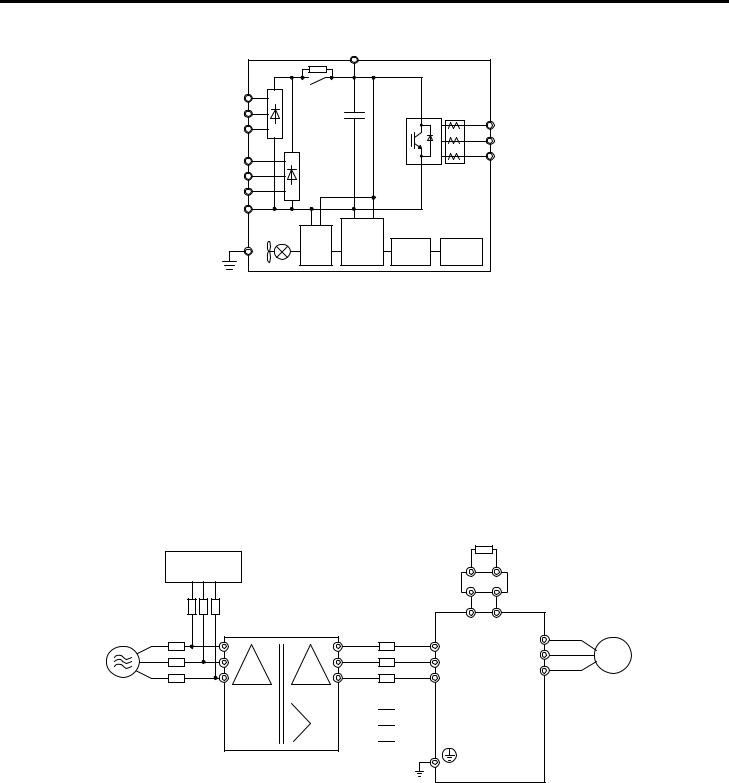
u Main Circuit Connection Diagram
Refer to Figure 5, Figure 6, and Figure 7 when wiring the main circuit of the drive. Connections may vary based on drive capacity.
NOTICE: Do not use the negative DC bus terminal “ ” as a ground terminal. This terminal is at high DC voltage potential. Improper wiring connections could damage the drive.
n 6-Phase/12-Pulse Input 400 V Class Models 4T0058o and 4T0072o
|
B1 |
B2 |
Relay |
|
|
R/L1 |
|
Current |
S/L2 |
|
Sensor |
T/L3 |
|
U/T1 |
|
|
V/T2 |
R1/L11 |
|
W/T3 |
|
|
|
S1/L21 |
|
|
T1/L31 |
|
|
– |
|
|
Gate |
|
|
Board |
Control |
Operator |
|
||
|
Board |
|
|
|
Figure 5 Connecting Main Circuit Terminals
n 6-Phase/12-Pulse Input 400 V Class Models 4T0088o to 4T0139o
|
+3 |
|
|
|
Relay |
|
|
R/L1 |
|
|
Current |
S/L2 |
|
|
Sensor |
T/L3 |
|
|
U/T1 |
|
|
|
V/T2 |
R1/L11 |
|
|
W/T3 |
|
|
|
|
S1/L21 |
|
|
|
T1/L31 |
|
|
|
– |
|
|
|
|
Gate |
|
|
|
Board |
Control |
Operator |
|
|
||
|
|
Board |
|
|
|
|
Figure 6 Connecting Main Circuit Terminals
18 |
YASKAWA TOEP YAIA1U 02A YASKAWA AC Drive – A1000 6-Phase/12-Pulse Input Installation Manual |
3 Electrical Installation
n 6-Phase/12-Pulse Input 400 V Class Models 4T0165o to 4T0675o
|
|
+3 |
|
|
R/L1 |
Relay |
|
|
Current |
|
+ |
|
||
S/L2 |
|
|
Sensor |
|
|
|
|
||
T/L3 |
|
|
|
U/T1 |
|
|
|
|
V/T2 |
R1/L11 |
|
|
|
W/T3 |
|
|
|
|
|
S1/L21 |
|
|
|
|
T1/L31 |
|
|
|
|
|
|
|
|
|
|
24 V |
Gate |
|
|
|
Power |
Control |
|
|
|
Board |
Operator |
||
|
Supply |
|
Board |
|
|
|
|
Figure 7 Connecting Main Circuit Terminals
n 6-Phase/12-Pulse Rectification
Installing a Transformer
Install a 6-Phase/12-Pulse isolation transformer with output windings phase-shifted by 30 electrical degrees or install a Hybrid 6-Phase topology on the power supply.
Installing a 3-Phase Line Monitor
Yaskawa requires installation of a 3-Phase line monitor to protect the drive in the event of an input line phase loss.
The 3-Phase line monitor must be installed on the primary circuit of the 6-Phase/12-Pulse transformer and connected to the drive to remove the Run command when a phase loss condition occurs.
The drive power circuit may be damaged during a phase-loss condition if a 3-Phase line monitor is not properly installed. Contact a Yaskawa representative for help selecting the optimum 3-Phase line monitor and fuses.
Connection Diagram
|
3-Phase Line Monitor |
|
|
Dynamic braking resistor |
||
|
|
|
|
|
(option) <1> |
|
|
|
|
|
|
CDBR dynamic braking unit |
|
|
|
|
|
|
(option) <2> |
|
|
|
Fuse |
|
|
|
|
Main Circuit |
<3> |
6-Phase/12-Pulse |
<4> |
+3 |
|
|
Isolation Transformer |
|
|||||
Power Supply |
BCP |
|
Fuse |
R/L1 |
U/T1 |
|
|
|
|
|
|
||
|
|
|
|
V/T2 |
Motor |
|
|
|
|
|
S/L2 |
||
|
|
|
|
W/T3 |
|
|
|
|
|
|
T/L3 |
|
|
|
|
|
|
|
|
|


 R1/L11


 S1/L21


 T1/L31
Figure 8 Main Circuit Terminal Connections
<1> A dynamic braking resistor can be connected to the B1 and B2 terminals on models 4T0058o and 4T0072o. <2> A CDBR dynamic braking unit cannot be connected to models 4T0058o or 4T0072o.
<3> Refer to local codes for proper branch circuit protection (BCP) on the primary side of the 6-Phase/12-Pulse transformer. <4> Fuse selection for the secondary side is of the 6-Phase/12-Pulse transformer is shown in Table 13 and Table 14
YASKAWA TOEP YAIA1U 02A YASKAWA AC Drive – A1000 6-Phase/12-Pulse Input Installation Manual |
19 |

3 Electrical Installation
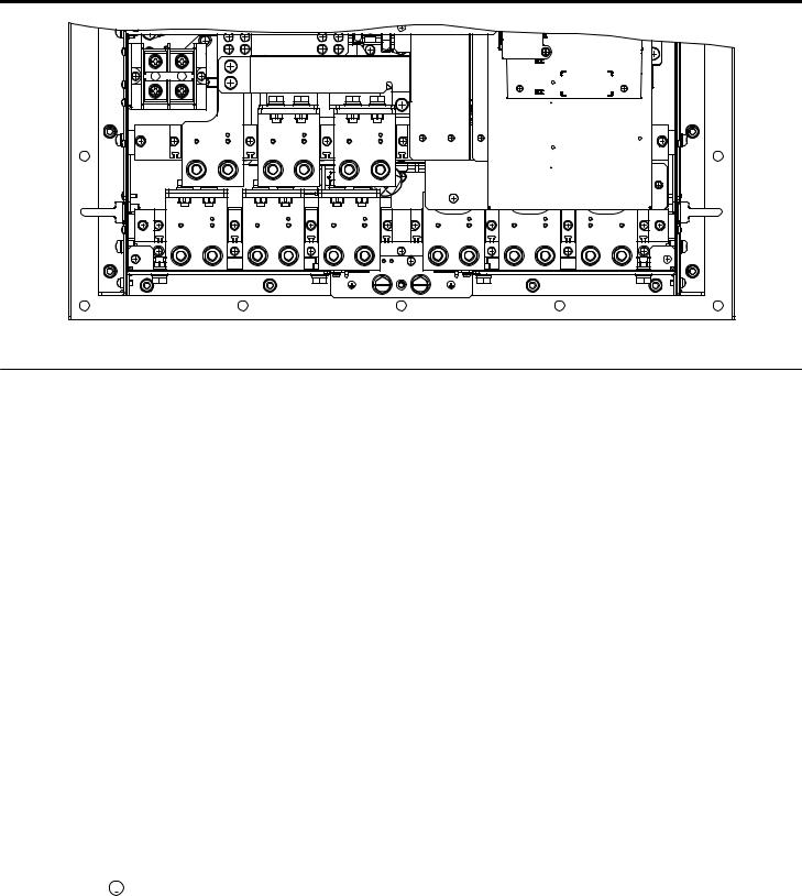
u Terminal Specifications
Figure 9 to Figure 15 show the different terminal arrangements for the drive capacities.
B1 |
B2 |
|
|
|
|
|
|
|
R1/L11 |
|
S1/L21 |
T1/L31 |
|
|
R/L1 |
S/L2 |
T/L3 |
U/T1 |
V/T2 |
W/T3 |
Figure 9 Model 4T0058o and 4T0072o Terminals |
||||||
3 |
|
|
|
|
|
|
R/L1 |
S/L2 |
T/L3 |
R1/L11 S1/L21 T1/L31 |
U/T1 |
V/T2 |
W/T3 |
|
Figure 10 |
Models 4T0088o and 4T0103o Terminals |
|
||
R/L1 |
S/L2 T/L3 R1/L11 S1/L21 T1/L31 |
U/T1 |
V/T2 |
W/T3 |
|
3 |
|
|
|||
|
Figure 11 |
Models 4T0139o and 4T0165o Terminals |
|
||
20 |
YASKAWA TOEP YAIA1U 02A YASKAWA AC Drive – A1000 6-Phase/12-Pulse Input Installation Manual |
3 Electrical Installation
|
3 |
|
|
|
|
R1/L11 |
S1/L21 |
T1/L31 |
|
|
|
R/L1 |
S/L2 |
T/L3 |
U/T1 |
V/T2 |
W/T3 |
Figure 12 Model 4T0208o Terminals
|
+3 |
|
|
|
|
|
|
|
R1/L11 |
S1/L21 |
T1/L31 |
|
|
|
R/L1 |
S/L2 |
T/L3 |
U/T1 |
V/T2 |
W/T3 |
|
Figure 13 Models 4T0250o to 4T0362o Terminals |
|||||
|
+3 |
|
|
|
|
|
|
|
R1/L11 |
S1/L21 |
T1/L31 |
|
|
|
R/L1 |
S/L2 |
T/L3 |
U/T1 |
V/T2 |
W/T3 |
Figure 14 Model 4T0414o Terminals
YASKAWA TOEP YAIA1U 02A YASKAWA AC Drive – A1000 6-Phase/12-Pulse Input Installation Manual |
21 |
3 Electrical Installation
|
+3 |
|
|
|
|
|
|
R1/L11 |
S1/L21 |
T1/L31 |
|
|
|
|
R/L1 |
S/L2 |
T/L3 |
U/T1 |
V/T2 |
W/T3 |
|
|
Figure 15 Models 4T0515o and 4T0675o Terminals |
|
|||
u Main Circuit Wiring
This section describes the functions, specifications, and procedures required to safely and properly wire the main circuit in the drive.
NOTICE: Do not solder the ends of wire connections to the drive. Soldered wiring connections can loosen over time. Improper wiring practices could result in drive malfunction due to loose terminal connections.
NOTICE: Do not switch the drive input to start or stop the motor. Frequently switching the drive on and off shortens the life of the DC bus charge circuit and the DC bus capacitors, and can cause premature drive failures. For the full performance life, refrain from switching the drive on and off more than once every 30 minutes.
n Main Circuit Terminal Functions
|
|
|
|
|
Table 4 Main Circuit Terminal Functions |
|
||
|
Terminal |
|
Type |
Function |
||||
|
Model |
4T0058o and 4T0072o |
4T0088o to 4T0675o |
|||||
|
|
|||||||
|
R/L1 |
|
|
|
|
|||
|
S/L2 |
|
|
|
|
|||
|
T/L3 |
Main circuit power supply input Not available |
Connects line power to the drive |
|||||
|
R1/L11 |
|||||||
|
|
|
|
|
||||
|
S1/L21 |
|
|
|
|
|||
|
T1/L31 |
|
|
|
|
|||
|
U/T1 |
|
|
|
|
|||
|
V/T2 |
|
Drive output |
Connects to the motor |
||||
|
W/T3 |
|
|
|
|
|||
|
B1 |
Braking resistor |
|
Not available |
Available for connecting a braking resistor or a |
|||
|
B2 |
|
braking resistor unit option |
|||||
|
|
|
|
|||||
|
|
|
Not available |
|
Braking unit connection |
Only for connecting dynamic braking options |
||
|
3 |
|
( 3 and ) |
|||||
|
|
|
|
|||||
|
|
|
|
|
|
10 Ω or less |
Grounding terminal |
|
|
|
|
|
|
|
|||
Note: |
Note: DC power supply input is not available for 6-Phase/12-Pulse Input models. |
|
||||||
n Main Circuit Fuses
The 6-Phase/12-Pulse drive requires fuses to be installed on each of the 6 input phases between the 6-Phase/12- Pulse transformer and the drive. Select fuses from Table 13 or Table 14 according to drive model to maintain standards compliance.
22 |
YASKAWA TOEP YAIA1U 02A YASKAWA AC Drive – A1000 6-Phase/12-Pulse Input Installation Manual |

3 Electrical Installation
u Wire Gauges and Tightening Torques
Use the tables in this section to select the appropriate wires and crimp terminals. Gauges listed in the tables are for use in the United States.
Note: |
1. Wire gauge recommendations based on drive continuous current ratings (ND) using 75 °C 600 Vac vinyl-sheathed wire assuming ambient |
|
temperature within 40 °C and wiring distance shorter than 100 m. |
2.Terminals 3 and are for connecting optional power devices. Use caution to connect only approved devices to the correct terminal(s).
•Consider the amount of voltage drop when selecting wire gauges. Increase the wire gauge when the voltage drop is greater than 2% of motor rated voltage. Ensure the wire gauge is suitable for the terminal block. Use the following formula to calculate the amount of voltage drop:
Line drop voltage (V) =  3 × wire resistance (Ω/km) × wire length (m) × current (A) × 10-3
•Refer to CDBR manual TOBP C720600 00/TOBP C720600 01 for dynamic braking wire gauges.
•Use terminals 3 and when connecting a CDBR dynamic braking unit.
•Do not connect a regenerative converter or a regenerative unit to the 6-Phase/12-Pulse drive.
•Refer to UL Standards on page 84 for information on UL compliance.
Yaskawa recommends using closed-loop crimp terminals on all drive models. UL/cUL approval requires the use of closedloop crimp terminals when wiring the drive main circuit terminals. Use only the tools recommended by the terminal manufacturer for crimping. Refer to Closed-Loop Crimp Terminal Size on page 86 for closed-loop crimp terminal recommendations.
The wire gauges listed in Table 5 are Yaskawa recommendations and are based on the 6-Phase input current ratings specified in Table 14. Refer to local codes for proper wire gauge selections.
Table 5 Wire Gauge and Torque Specifications
Drive Model |
|
|
|
Terminal |
Wire Range |
Screw |
Tightening Torque |
|
|
|
|
AWG, kcmil |
Size |
N·m (lb.in.) |
|||
|
|
|
|
|
||||
|
R/L1, S/L2, T/L3 |
|
|
9 to 11 |
||||
|
R1/L11, S1/L21, T1/L31 |
10 to 1/0 (5.3 to 53.5) |
M8 |
|||||
|
(79.7 to 97.4) |
|||||||
4T0058o |
U/T1, V/T2, W/T3 |
|
|
|||||
|
|
|
||||||
B1, B2 |
22 to 10 (0.3 to 5.3) |
M4 |
1.2 (10.6) |
|||||
|
||||||||
|
|
|
|
|
Refer to applicable codes for wire size |
M8 |
9 to 11 |
|
|
|
|
|
|
(79.7 to 97.4) |
|||
|
|
|
|
|
|
|
||
|
R/L1, S/L2, T/L3 |
|
|
9 to 11 |
||||
|
R1/L11, S1/L21, T1/L31 |
10 to 3/0 (5.3 to 85.0) |
M8 |
|||||
|
(79.7 to 97.4) |
|||||||
4T0072o |
U/T1, V/T2, W/T3 |
|
|
|||||
|
|
|
||||||
B1, B2 |
22 to 10 (0.3 to 5.3) |
M4 |
1.2 (10.6) |
|||||
|
||||||||
|
|
|
|
|
Refer to applicable codes for wire size |
M8 |
9 to 11 |
|
|
|
|
|
|
(79.7 to 97.4) |
|||
|
|
|
|
|
|
|
||
|
R/L1, S/L2, T/L3 |
|
|
|
||||
4T0088o |
R1/L11, S1/L21, T1/L31 |
6 to 250 (13.3 to 127) |
M8 |
9 to 11 (79.7 to 97.4) |
||||
U/T1, V/T2, W/T3 |
|
|
|
|||||
4T0103o |
|
|
|
|||||
, 3 |
22 to 1/0 (0.3 to 53.5) |
M6 |
2.5 to 3.0 (22.1 to 26.6) |
|||||
|
||||||||
|
|
|
|
|
Refer to applicable codes for wire size |
M8 |
9 to 11 (79.7 to 97.4) |
|
|
|
|
|
|
||||
|
R/L1, S/L2, T/L3 |
|
|
2.5 to 3.0 |
||||
|
R1/L11, S1/L21, T1/L31 |
22 to 1/0 (0.3 to 53.5) |
M6 |
|||||
|
(22 to 1/0) |
|||||||
4T0139o |
, 3 |
|
|
|||||
|
|
|
||||||
4T0165o |
|
|
|
|
|
|
|
|
U/T1, V/T2, W/T3 |
6 to 250 (13.3 to 127) |
M8 |
15.0 (132.8) |
|||||
|
||||||||
|
|
|
|
|
Refer to applicable codes for wire size |
M10 |
18 to 23 |
|
|
|
|
|
|
(159.3 to 203.6) |
|||
|
|
|
|
|
|
|
||
|
R/L1, S/L2, T/L3 |
|
|
18 to 23 |
||||
|
R1/L11, S1/L21, T1/L31 |
Refer to applicable codes for wire size |
M10 |
|||||
|
(159.3 to 203.6) |
|||||||
4T0208o |
U/T1, V/T2, W/T3 |
|
|
|||||
|
|
|
||||||
, 3 |
22 to 1/0 (0.3 to 53.5) |
M6 |
2.5 to 3.0 |
|||||
|
||||||||
|
(22.1 to 26.6) |
|||||||
|
|
|
|
|
|
|
||
|
|
|
|
|
Refer to applicable codes for wire size |
M10 |
18 to 23 |
|
|
|
|
|
|
(159.3 to 203.6) |
|||
|
|
|
|
|
|
|
||
YASKAWA TOEP YAIA1U 02A YASKAWA AC Drive – A1000 6-Phase/12-Pulse Input Installation Manual |
23 |

3 Electrical Installation
Drive Model |
|
|
|
Terminal |
Wire Range |
Screw |
Tightening Torque |
|
|
|
|
AWG, kcmil |
Size |
N·m (lb.in.) |
|||
|
|
|
|
|
||||
|
R/L1, S/L2, T/L3 |
|
|
18 to 23 |
||||
|
R1/L11, S1/L21, T1/L31 |
Refer to applicable codes for wire size |
M10 |
|||||
|
(159.3 to 203.6) |
|||||||
4T0250o |
U/T1, V/T2, W/T3 |
|
|
|||||
|
|
|
||||||
, 3 |
22 to 1/0 (0.3 to 53.5) |
M6 |
2.5 to 3.0 |
|||||
|
||||||||
|
(22.1 to 26.6) |
|||||||
|
|
|
|
|
|
|
||
|
|
|
|
|
Refer to applicable codes for wire size |
M10 |
18 to 23 |
|
|
|
|
|
|
(159.3 to 203.6) |
|||
|
|
|
|
|
|
|
||
|
R/L1, S/L2, T/L3 |
|
M10 |
18 to 23 |
||||
|
R1/L11, S1/L21, T1/L31 |
Refer to applicable codes for wire size |
(159.3 to 203.6) |
|||||
|
|
|||||||
|
U/T1, V/T2, W/3 |
M12 |
32 to 40 |
|||||
|
|
|||||||
4T0296o |
|
(283.2 to 354.0) |
||||||
|
|
|
|
|
|
|||
, 3 |
22 to 1/0 (0.3 to 53.5) |
M6 |
2.5 to 3.0 |
|||||
|
||||||||
|
(22.1 to 26.6) |
|||||||
|
|
|
|
|
|
|
||
|
|
|
|
|
Refer to applicable codes for wire size |
M12 |
32 to 40 |
|
|
|
|
|
|
(283.2 to 354.0) |
|||
|
|
|
|
|
|
|
||
|
R/L1, S/L2, T/L3 |
|
M10 |
18 to 23 |
||||
|
R1/L11, S1/L21, T1/L31 |
Refer to applicable codes for wire size |
(159.3 to 203.6) |
|||||
|
|
|||||||
|
U/T1, V/T2, W/T3 |
M12 |
32 to 40 |
|||||
|
|
|||||||
4T0362o |
|
(283.2 to 354.0) |
||||||
|
|
|
|
|
|
|||
, 3 |
22 to 1/0 (0.3 to 53.5) |
M6 |
2.5 to 3.0 |
|||||
|
||||||||
|
(22.1 to 26.6) |
|||||||
|
|
|
|
|
|
|
||
|
|
|
|
|
Refer to applicable codes for wire size |
M12 |
32 to 40 |
|
|
|
|
|
|
(283.2 to 354.0) |
|||
|
|
|
|
|
|
|
||
|
R/L1, S/L2, T/L3 |
|
|
32 to 40 |
||||
|
R1/L11, S1/L21, T1/L31 |
Refer to applicable codes for wire size |
M12 |
|||||
|
(283.2 to 354.0) |
|||||||
4T0414o |
U/T1, V/T2, W/T3 |
|
|
|||||
|
|
|
||||||
, 3 |
22 to 1/0 (0.3 to 53.5) |
M6 |
2.5 to 3.0 |
|||||
|
||||||||
|
(22.1 to 26.6) |
|||||||
|
|
|
|
|
|
|
||
|
|
|
|
|
Refer to applicable codes for wire size |
M12 |
32 to 40 |
|
|
|
|
|
|
(283.2 to 354.0) |
|||
|
|
|
|
|
|
|
||
|
R/L1, S/L2, T/L3 |
|
|
32 to 40 |
||||
|
R1/L11, S1/L21, T1/L31 |
Refer to applicable codes for wire size |
M12 |
|||||
|
(283.2 to 354.0) |
|||||||
4T0515o |
U/T1, V/T2, W/T3 |
|
|
|||||
|
|
|
||||||
, 3 |
13.3 to 127 (6 to 250) |
M8 |
13.5 to 15 |
|||||
|
||||||||
|
(119.5 to 132.8) |
|||||||
|
|
|
|
|
|
|
||
|
|
|
|
|
Refer to applicable codes for wire size |
M12 |
32 to 40 |
|
|
|
|
|
|
(283.2 to 354.0) |
|||
|
|
|
|
|
|
|
||
|
R/L1, S/L2, T/L3 |
|
|
32 to 40 |
||||
|
R1/L11, S1/L21, T1/L31 |
Refer to applicable codes for wire size |
M12 |
|||||
|
(283.2 to 354.0) |
|||||||
4T0675o |
U/T1, V/T2, W/T3 |
|
|
|||||
|
|
|
||||||
, 3 |
13.3 to 127 (6 to 250) |
M8 |
13.5 to 15 |
|||||
|
||||||||
|
(119.5 to 132.8) |
|||||||
|
|
|
|
|
|
|
||
|
|
|
|
|
Refer to applicable codes for wire size |
M12 |
32 to 40 |
|
|
|
|
|
|
(283.2 to 354.0) |
|||
|
|
|
|
|
|
|
||
u Wiring Checklist
|
No. |
Item |
Page(s) |
|
|
|
|
|
|
Drive, Peripherals, Option Cards |
|
|
1 |
Check drive model number to ensure receipt of correct model. |
10 |
|
|
|
|
|
2 |
Make sure you have the correct braking resistors, DC link chokes, noise filters, and other peripheral devices. |
|
|
|
|
|
|
3 |
Check the option card model number. |
|
|
|
|
|
|
|
Installation Area and Physical Setup |
|
|
4 |
Ensure that the area surrounding the drive complies with specifications. |
13 |
|
|
|
|
|
|
Power Supply Voltage, Output Voltage |
|
24 |
YASKAWA TOEP YAIA1U 02A YASKAWA AC Drive – A1000 6-Phase/12-Pulse Input Installation Manual |
3 Electrical Installation
|
No. |
Item |
Page(s) |
|
|
|
|
5 |
The voltage from the power supply should be within the input voltage specification range of the drive. |
– |
|
|
|
|
|
6 |
The voltage rating for the motor should match the drive output specifications. |
10 |
|
|
|
|
|
|
|
|
|
7Verify that the drive is properly sized to run the motor.
Main Circuit Wiring
8 |
Confirm proper branch circuit protection as specified by national and local codes. |
15 |
|
|
Properly wire the power supply to drive terminals R/L1, S/L2, T/L3, R1/L11, S1/L21, and T1/L31. |
|
|
9 |
Note: |
Confirm that a 6-Phase/12-Pulse isolation transformer with each of the output windings phase-shifted |
18 |
|
|
by 30 electrical degrees or a Hybrid 6-Phase topology is installed on the power supply. |
|
10 |
Properly wire the drive and motor together. |
– |
|
The motor lines and drive output terminals U/T1, V/T2, and W/T3 should match in order to produce the desired phase |
|||
|
order. If the phase order is incorrect, the drive will rotate in the opposite direction. |
|
|
11 |
Use 600 Vac vinyl-sheathed wire for the power supply and motor lines. |
23 |
|
|
|
|
|
|
Use the correct wire gauges for the main circuit. |
|
|
|
• Consider the amount of voltage drop when selecting wire gauges. Increase the wire gauge when the voltage drop is |
|
|
12 |
greater than 2% of motor rated voltage. Ensure the wire gauge is suitable for the terminal block. Use the following |
23 |
|
formula to calculate the amount of voltage drop: |
|||
Line drop voltage (V) =  3 × wire resistance (Ω/km) × wire length (m) × current (A) × 10-3
|
|
• If the cable between the drive and motor exceeds 50 m, adjust the carrier frequency set to C6-02 accordingly. |
|
||||||||||||||||
13 |
Properly ground the drive. |
|
|
|
|
|
|
|
|
|
|
|
|
|
|
– |
|||
|
|
|
|
|
|
|
|
|
|
||||||||||
14 |
Tighten control circuit and grounding terminal screws. |
|
|
|
|
|
|
23 |
|||||||||||
|
|
|
|
||||||||||||||||
|
|
Set up overload protection circuits when running multiple motors from a single drive. |
|
||||||||||||||||
|
|
|
Power supply |
|
|
|
|
|
|
|
|
|
|
|
|
|
|
|
|
|
|
|
Drive |
|
|
|
|
|
MC1 |
OL1 |
|
|
|
||||||
|
|
|
|
|
|
|
|
|
|
|
|
|
|||||||
|
|
|
|
|
|
|
|
|
|
|
|
|
|
|
|
M1 |
|
|
|
|
|
|
|
|
|
|
|
|
|
|
|
|
|
|
|
|
|
||
15 |
|
|
|
|
|
|
|
|
|
MC2 |
OL2 |
MC1 - MCn |
... magnetic contactor |
– |
|||||
|
|
|
|
|
|
|
|
|
|
|
|
|
|
|
|
M2 |
OL 1 - OL n |
... thermal relay |
|
|
|
|
|
|
|
|
|
|
|
|
|
|
|
|
|
|
|||
|
|
|
|
|
|
|
|
|
|
|
MCn |
OLn |
|
|
|
||||
|
|
Note: |
|
|
|
|
|
|
|
|
|
|
|
|
|
Mn |
|
|
|
|
|
Close MC1 – MCn before operating the drive. MC1 – MCn cannot be switched off during run. |
|
||||||||||||||||
16 |
Install a magnetic contactor when using a dynamic braking option. Properly install the resistor and ensure that overload |
– |
|||||||||||||||||
protection shuts off the power supply using the magnetic contactor. |
|
|
|||||||||||||||||
|
|
|
|
|
|||||||||||||||
17 |
Verify phase advancing capacitors, input noise filters, or GFCIs are NOT installed on the output side of the drive. |
– |
|||||||||||||||||
|
|
|
|
|
|
|
|
|
|||||||||||
|
|
|
|
|
Control Circuit Wiring |
|
|
|
|||||||||||
|
18 |
Use twisted-pair line for all drive control circuit wiring. |
|
|
|
|
|
|
– |
||||||||||
|
|
|
|
|
|
|
|
|
|
|
|
|
|
|
|||||
|
19 |
Ground the shields of shielded wiring to the GND |
|
|
|
|
terminal. |
|
|
|
|
|
|
– |
|||||
|
|
|
|
|
|
|
|
|
|
||||||||||
|
|
|
|
||||||||||||||||
|
20 |
For 3-Wire sequence, set parameters for multi-function contact input terminals S1 – S8, and wire control circuits. |
– |
||||||||||||||||
|
|
|
|
|
|
|
|
|
|
|
|
|
|
|
|
|
|
||
|
21 |
Properly wire any option cards. |
|
|
|
|
|
|
|
|
|
|
|
|
|
|
– |
||
|
|
|
|
|
|||||||||||||||
|
22 |
Check for any other wiring mistakes. Only use a multimeter to check wiring. |
|
– |
|||||||||||||||
|
|
|
|
|
|
|
|
|
|
|
|
||||||||
|
23 |
Properly fasten drive control circuit terminal screws. |
|
|
|
|
|
|
|
|
23 |
||||||||
|
|
|
|
|
|
|
|
|
|
|
|
|
|
|
|
|
|
||
|
24 |
Pick up all wire clippings. |
|
|
|
|
|
|
|
|
|
|
|
|
|
|
– |
||
|
|
|
|
||||||||||||||||
|
25 |
Ensure that no frayed wires on the terminal block are touching other terminals or connections. |
– |
||||||||||||||||
|
|
|
|
|
|
||||||||||||||
|
26 |
Properly separate control circuit wiring and main circuit wiring. |
|
|
– |
||||||||||||||
|
|
|
|
|
|
|
|
|
|
|
|
||||||||
|
27 |
Analog signal line wiring should not exceed 50 m. |
|
|
|
|
|
|
|
|
– |
||||||||
|
|
|
|
|
|
|
|
|
|
|
|
||||||||
|
28 |
Safe Disable input wiring should not exceed 30 m. |
|
|
|
|
|
|
|
|
– |
||||||||
|
|
|
|
|
|
|
|
|
|
|
|
|
|
|
|
|
|
|
|
YASKAWA TOEP YAIA1U 02A YASKAWA AC Drive – A1000 6-Phase/12-Pulse Input Installation Manual |
25 |

4Start-Up Programming & Operation
4Start-Up Programming & Operation
u Powering Up the Drive
Review the following checklist before applying power.
Item to Check |
Description |
|
|
6-Phase/12-Pulse Isolated 380 to 480 Vac 50/60 Hz, 30 electrical degrees phase-shifted each phase |
|
Power supply |
Properly wire the power supply input terminals (R/L1, S/L2, T/L3, R1/L11, S1/L21, T1/L31). <1> |
|
|
Check for proper grounding of drive and motor. |
|
Drive output terminals and |
Properly wire drive output terminals U/T1, V/T2, and W/T3 with motor terminals U, V, and W. |
|
motor terminals |
||
|
||
Control circuit terminals |
Check control circuit terminal connections. |
|
Drive control terminal status |
Open all control circuit terminals (off). |
|
Status of the load and connected |
Decouple the motor from the load. |
|
machinery |
|
<1> Install a 6-Phase/12-Pulse isolation transformer with each of the output windings phase-shifted by 30 electrical degrees or use a Hybrid 6-Phase topology.
26 |
YASKAWA TOEP YAIA1U 02A YASKAWA AC Drive – A1000 6-Phase/12-Pulse Input Installation Manual |

5 Troubleshooting
5Troubleshooting
NOTICE
Refer to the A1000 Technical Manual SIEP C710616 41 for information on Troubleshooting and complete product instructions necessary for proper installation, set-up, troubleshooting and maintenance.
The A1000 Technical Manual is posted on the Yaskawa website, www.yaskawa.com.
 WARNING
Electrical Shock Hazard
Do not connect or disconnect wiring while the power is on.
Failure to comply could result in death or serious injury.
Before servicing, disconnect all power to the equipment. The internal capacitor remains charged even after the power supply is turned off. The charge indicator LED will extinguish when the DC bus voltage is below 50 Vdc. To prevent electric shock, wait for at least the time specified on the warning label; after all indicators are OFF, measure for unsafe voltages to confirm the drive is safe prior to servicing.
Do not operate equipment with covers removed.
Failure to comply could result in death or serious injury.
The diagrams in this section may illustrate drives without covers or safety shields to display details. Be sure to reinstall covers or shields before operating the drives and run the drives according to the instructions described in this manual.
Do not touch terminals before the capacitors have fully discharged.
Failure to comply could result in death or serious injury.
Before servicing, disconnect all power to the equipment. The internal capacitor remains charged even after the power supply is turned off. The charge indicator LED will extinguish when the DC bus voltage is below 50 Vdc. To prevent electric shock, wait for at least the time specified on the warning label; after all indicators are OFF, measure for unsafe voltages to confirm the drive is safe prior to servicing.
After blowing a fuse or tripping a GFCI, do not attempt to restart the drive or operate peripheral devices until five minutes pass and CHARGE lamp is OFF.
Failure to comply could result in death, serious injury, and damage to the drive. Check wiring and peripheral device ratings to identify the cause of trips. Contact your supplier if the cause cannot be identified.
Installation, maintenance, inspection and servicing must be performed only by authorized personnel familiar with installation, adjustment and maintenance of AC drives.
Do not perform work on the drive while wearing loose clothing, jewelry, or without eye protection.
Failure to comply could result in death or serious injury.
Do not remove covers or touch circuit boards while the power is on.
Failure to comply could result in death or serious injury.
YASKAWA TOEP YAIA1U 02A YASKAWA AC Drive – A1000 6-Phase/12-Pulse Input Installation Manual |
27 |

5 Troubleshooting
u Fault Reset Methods
When a fault occurs, the cause of the fault must be removed and the drive must be restarted. The table below lists the different ways to restart the drive.
After the Fault Occurs |
|
Procedure |
|
|
|
|
|
|
|
|
|
|
ALM |
|
|
|
|
|
- MODE - |
DRV |
|
|
|
|
|
oC |
|
Fix the cause of the fault, restart the drive, and |
|
|
|
|
Overcurrent |
|
Press |
on the digital operator when the error code |
|
|
FWD RESET |
||
reset the fault |
|
|
F1 |
F2 |
||
is displayed. |
RESET |
|
ESC |
|
||
|
|
RE |
||||
|
|
|
|
|
|
LO |
|
|
|
|
|
RESET |
ENTER |
|
|
|
|
|
RUN |
STOP |
|
Close then open the fault signal digital input via |
Fault Reset Switch |
Drive |
|||
Resetting via Fault Reset Digital Input S4 |
S4 Fault Reset Digital Input |
|||||
terminal S4. S4 is set for “Fault Reset” as default |
|
|
SC Digital Input Common |
|||
|
(H1-04 = 14). |
|
|
|||
|
|
|
|
|
||
|
|
|
2 |
ON |
|
|
Turn off the main power supply if the above methods do not reset the fault. Reapply power after the |
|
|
|
|
||
digital operator display has turned off. |
|
|
|
|
|
|
|
|
|
1 OFF |
|
||
Note: If the Run command is present, the drive will disregard any attempts to reset the fault. Remove the Run command before attempting to clear a fault situation.
28 |
YASKAWA TOEP YAIA1U 02A YASKAWA AC Drive – A1000 6-Phase/12-Pulse Input Installation Manual |
Loading...