


 Loading...
YASKAWA
Machine Controller MP900 Series
260IF DeviceNet System
USER’S MANUAL
YASKAWA |
MANUAL NO. SIEZ-C887-5.2 |

Safety Information
Safety Information
The following conventions are used to indicate precautions in this manual. Failure to heed precautions provided in this manual can result in serious or possibly even fatal injury or damage to the products or to related equipment and systems.
WARNING |
Indicates precautions that, if not heeded, could possibly result in loss of life or seri- |
|
ous injury. |
Caution |
Indicates precautions that, if not heeded, could result in relatively serious or minor |
|
injury, damage to the product, or faulty operation. |
In some situations, the precautions indicated could have serious consequences if not heeded.


 Prohibited

 Mandatory
Indicates prohibited actions that must not be performed. For example, this symbol would be used to indicate that fire is prohibited as follows: 
 .
.
Indicates compulsory actions that must be performed. For example, this symbol would be used as follows to indicate that grounding is compulsory:
 .
.
iii
Safety Information
Visual Aids
The following aids are used to indicate certain types of information for easier reference.
Indicates important information that should be memorized.
Also, indicates low-level precautions that, if not heeded, may cause an alarm to sound but will not result in the device being damaged.
INFO |
Indicates additional information or information that is useful to have memorized. |
Describes technical terms that are difficult to understand, or appear in the text without an explanation being given.
Copyright © Yaskawa Electric Corporation, 2000.
All rights reserved. No part of this publication may be reproduced, stored in a retrieval system, or transmitted, in any form, or by any means, mechanical, electronic, photocopying, recording, or otherwise, without the prior written permission of Yaskawa. No patent liability is assumed with respect to the use of the information contained herein. Moreover, because Yaskawa is constantly striving to improve its high-quality products, the information contained in this manual is subject to change without notice. Every precaution has been taken in the preparation of this manual. Nevertheless, Yaskawa assumes no responsibility for errors or omissions. Neither is any liability assumed for damages resulting from the use of the information contained in this publication.
iv

CONTENTS
CONTENTS
Safety Information - - - - - - - - - - - - - - - - - - - - - - - - - - - - - - - - - - - - - - iii Visual Aids - - - - - - - - - - - - - - - - - - - - - - - - - - - - - - - - - - - - - - - - - - - iv About This Manual - - - - - - - - - - - - - - - - - - - - - - - - - - - - - - - - - - - - - - ix Related Manuals - - - - - - - - - - - - - - - - - - - - - - - - - - - - - - - - - - - - - - - x Using This Manual - - - - - - - - - - - - - - - - - - - - - - - - - - - - - - - - - - - - - - xi Registered Trademark - - - - - - - - - - - - - - - - - - - - - - - - - - - - - - - - - - - xi Safety Precautions - - - - - - - - - - - - - - - - - - - - - - - - - - - - - - - - - - - - xii
1 Outline - - - - - - - - - - - - - - - - - - - - - - - - - - - - - - - - - - - - - - -1-1
1.1 Outline of Configuration and Functions - - - - - - - - - - - - - - - - 1-2
1.1.1 System Configuration - - - - - - - - - - - - - - - - - - - - - - - - - - - - - - - - - - -1-2
1.1.2 Master Mode - - - - - - - - - - - - - - - - - - - - - - - - - - - - - - - - - - - - - - - - -1-3
1.1.3 Slave Mode - - - - - - - - - - - - - - - - - - - - - - - - - - - - - - - - - - - - - - - - - -1-4
1.1.4 Functional Outline - - - - - - - - - - - - - - - - - - - - - - - - - - - - - - - - - - - - - -1-4
2 Basic Specifications - - - - - - - - - - - - - - - - - - - - - - - - - - - - - -2-1
2.1 Specifications - - - - - - - - - - - - - - - - - - - - - - - - - - - - - - - - - - 2-2
2.2 External Appearance - - - - - - - - - - - - - - - - - - - - - - - - - - - - 2-3
2.2.1 260IF Module - - - - - - - - - - - - - - - - - - - - - - - - - - - - - - - - - - - - - - - - -2-3
2.3 Switch Specifications - - - - - - - - - - - - - - - - - - - - - - - - - - - - 2-4
2.4 LED Indicator Specifications - - - - - - - - - - - - - - - - - - - - - - - 2-5
3 Network Specifications - - - - - - - - - - - - - - - - - - - - - - - - - - - -3-1
3.1 Network Configuration - - - - - - - - - - - - - - - - - - - - - - - - - - - 3-2
3.1.1 Basic Network Configuration - - - - - - - - - - - - - - - - - - - - - - - - - - - - - -3-2
3.1.2 Branching Methods - - - - - - - - - - - - - - - - - - - - - - - - - - - - - - - - - - - - -3-3
3.1.3 Network Configuration Restrictions - - - - - - - - - - - - - - - - - - - - - - - - - -3-6
4 System Startup and Setup - - - - - - - - - - - - - - - - - - - - - - - - -4-1
4.1 Basic Use of the 260IF Module - - - - - - - - - - - - - - - - - - - - - 4-2
4.1.1 Master Mode - - - - - - - - - - - - - - - - - - - - - - - - - - - - - - - - - - - - - - - - -4-2 4.1.2 Slave Mode - - - - - - - - - - - - - - - - - - - - - - - - - - - - - - - - - - - - - - - - - -4-3 4.1.3 Basic System Design Procedure - - - - - - - - - - - - - - - - - - - - - - - - - - -4-4 4.1.4 Device Setting Procedure - - - - - - - - - - - - - - - - - - - - - - - - - - - - - - - -4-5 4.1.5 I/O Allocations - - - - - - - - - - - - - - - - - - - - - - - - - - - - - - - - - - - - - - - -4-6
4.2 Calculating Communications Cycle Times - - - - - - - - - - - - - |
4-7 |
4.2.1 Communications Cycle Time - - - - - - - - - - - - - - - - - - - - - - - - - - - - - |
-4-7 |
4.2.2 Calculating Communications Cycle Times - - - - - - - - - - - - - - - - - - - - - |
4-7 |
4.2.3 Precautions on Setting the Communications Cycle Time - - - - - - - - - - |
4-9 |
v

4.3 260IF Module Setup - - - - - - - - - - - - - - - - - - - - - - - - - - - - 4-10
4.3.1 Opening the 260IF Module Configuration Window - - - - - - - - - - - - - - 4-10
4.3.2 Setting Methods - - - - - - - - - - - - - - - - - - - - - - - - - - - - - - - - - - - - - - 4-11
5 Programming - - - - - - - - - - - - - - - - - - - - - - - - - - - - - - - - - - 5-1
5.1 System Registers - - - - - - - - - - - - - - - - - - - - - - - - - - - - - - - 5-2
5.1.1 System Register and Communications Errors - - - - - - - - - - - - - - - - - - 5-2
5.2 Message Send Function (MSG-SND) - - - - - - - - - - - - - - - - - 5-3
5.2.1 Before using 260IF Module Message Communications - - - - - - - - - - |
- 5-3 |
5.2.2 Outline of Message Send Function - - - - - - - - - - - - - - - - - - - - - - - - |
- 5-4 |
5.2.3 Parameter List - - - - - - - - - - - - - - - - - - - - - - - - - - - - - - - - - - - - - - - |
- 5-5 |
5.2.4 Inputs - - - - - - - - - - - - - - - - - - - - - - - - - - - - - - - - - - - - - - - - - - - - - - |
5-9 |
5.2.5 Outputs - - - - - - - - - - - - - - - - - - - - - - - - - - - - - - - - - - - - - - - - - - - - |
5-10 |
5.2.6 Explicit Request Message - - - - - - - - - - - - - - - - - - - - - - - - - - - - - - - |
5-10 |
5.2.7 Explicit Response Messages - - - - - - - - - - - - - - - - - - - - - - - - - - - - |
5-11 |
6 Network Maintenance - - - - - - - - - - - - - - - - - - - - - - - - - - - - 6-1
6.1 Reading Network Configuration Information - - - - - - - - - - - - 6-2
6.1.1 Outline - - - - - - - - - - - - - - - - - - - - - - - - - - - - - - - - - - - - - - - - - - - - - 6-2 6.1.2 Using the Network Configuration Information Read Function - - - - - - - 6-2
6.2 I/O Status - - - - - - - - - - - - - - - - - - - - - - - - - - - - - - - - - - - - 6-5
6.2.1 Outline - - - - - - - - - - - - - - - - - - - - - - - - - - - - - - - - - - - - - - - - - - - - - 6-5
6.2.2 Using the I/O Status Function - - - - - - - - - - - - - - - - - - - - - - - - - - - - - 6-5
6.3 Status - - - - - - - - - - - - - - - - - - - - - - - - - - - - - - - - - - - - - - - 6-7
6.3.1 Using the Status Function - - - - - - - - - - - - - - - - - - - - - - - - - - - - - - - - 6-7
6.4 Troubleshooting - - - - - - - - - - - - - - - - - - - - - - - - - - - - - - - - 6-8
6.4.1 Masters - - - - - - - - - - - - - - - - - - - - - - - - - - - - - - - - - - - - - - - - - - - - - 6-8
6.4.2 Slaves - - - - - - - - - - - - - - - - - - - - - - - - - - - - - - - - - - - - - - - - - - - - 6-11
7 Wiring - - - - - - - - - - - - - - - - - - - - - - - - - - - - - - - - - - - - - - - 7-1
7.1 Wiring Communications Power Supply - - - - - - - - - - - - - - - - 7-2
7.1.1 Basic Precautions - - - - - - - - - - - - - - - - - - - - - - - - - - - - - - - - - - - - - 7-2 7.1.2 Wiring Power Supply - - - - - - - - - - - - - - - - - - - - - - - - - - - - - - - - - - - 7-2 7.1.3 Methods for Deciding the Power Supply Positioning - - - - - - - - - - - - - 7-3
7.2 Grounding the Network - - - - - - - - - - - - - - - - - - - - - - - - - - - 7-9
7.2.1 Grounding Methods - - - - - - - - - - - - - - - - - - - - - - - - - - - - - - - - - - - - 7-9
A External Appearances - - - - - - - - - - - - - - - - - - - - - - - - - - - -A-1
A.1 260IF Module - - - - - - - - - - - - - - - - - - - - - - - - - - - - - - - - - - - - - - - - - - A-2
A.2 MP940D Module - - - - - - - - - - - - - - - - - - - - - - - - - - - - - - - - - - - - - - - A-3
B Sample Programs - - - - - - - - - - - - - - - - - - - - - - - - - - - - - - -B-1
vi

CONTENTS
B.1 Sample Program No. 1 - - - - - - - - - - - - - - - - - - - - - - - - - - - - - - - - - - B-2 B.2 Sample Program No. 2 - - - - - - - - - - - - - - - - - - - - - - - - - - - - - - - - - - B-8
vii

About This Manual
About This Manual
This manual describes the DeviceNet Interface Option Module (called the 260IF Module) that is mounted to the Machine Controllers listed below to perform communications with DeviceNetTM devices.
•MP920 Machine Controller
•MP940 Machine Controller (built-in 260IF Module)
The DeviceNet is a multivendor field network. DeviceNet specifications are controlled by the ODVA Open DeviceNet Vendor Association, Inc.).
The 260IF Module is connected to a multivendor DeviceNet system and works as either a DeviceNet Master or Slave.
Refer to the DeviceNet Specifications published by the ODVA for information on the DeviceNet.
Read this manual before creating a DeviceNet system including MP900 Series Machine Controllers and store it in a safe place for future reference.
Refer to the following related manuals for information on the Controller.
viii

Related Manuals
Refer to the following related manuals as required.
Thoroughly check the specifications, restrictions, and other conditions of the product before use.
Manual Name |
Manual Number |
Contents |
|
|
|
MP900 Series Machine Controller |
SI-C887-1.2 |
Describes the instructions used in MP900 |
User’s Manual: |
|
Series ladder logic programming. |
Ladder Programming |
|
|
|
|
|
MP900 Series Machine Controller |
SI-C887-1.3 |
Describes the motion programming language |
User’s Manual: |
|
used for MP900 Series Machine Controllers. |
Motion Programming |
|
|
|
|
|
MP900 Series Machine Controller |
SIEZ-C887-2.3 |
Describes the installation and operating pro- |
Software User’s Manual: Program- |
(for simple operation) |
cedures for the CP-717 Programming Panel |
ming Panel Software (for simple |
(To be prepared), |
software used for MP900 Series Machine |
operation/standard operation) |
SIEZ-C887-2.4 |
Controllers. |
|
(for standard opera- |
|
|
tion) |
|
|
(To be prepared) |
|
|
|
|
MP920 Machine Controller |
SIZ-C887-2.1B |
Describes the design and maintenance for the |
User’s Manual: |
|
MP920 Machine Controller. |
Design and Maintenance |
|
|
|
|
|
MP940 Machine Controller |
SIZ-C887-4.1 |
Describes the design and maintenance for the |
User’s Manual: |
|
MP940 Machine Controller. |
Design and Maintenance |
|
|
|
|
|
ix

Using This Manual
Using This Manual
Intended Audience
This manual is intended for the following users.
•Those responsible for estimating the 260IF Module
•Those responsible for deciding whether to apply the 260IF Module
•Those responsible for designing the 260IF Module so that it can be mounted in the control and operation panels
•Those responsible for making, inspecting, testing, adjusting, and maintaining the control and operation panels in which the 260IF Module is mounted
Description of Technical Terms
In this manual, the following terms are defined as follows:
•PP = Programming Panel
•PC = Programmable Logic Controller
•260IF = The DeviceNet Option Module for use with MP900 Series Machine Controllers
•“--" in “MOV [axis1]--..." represents numeric data for axis 1.
Inverted Signals
In this manual, a slash (/) is placed in front of the name of any signal that is valid when low
(L).
•S-ON /S-ON
•P-CON /P-CON
Registered Trademark
•DeviceNet is a registered trademark of ODVA (Open DeviceNet Vender Association Inc.).
x
Safety Precautions
This section describes precautions that apply to correct use of devices. Before installing, operating, maintaining or inspecting devices, always read this manual and all other documents provided to ensure correct programming. Before using the equipment, familiarize yourself with equipment details, safety information, and all other precautions.
Installation


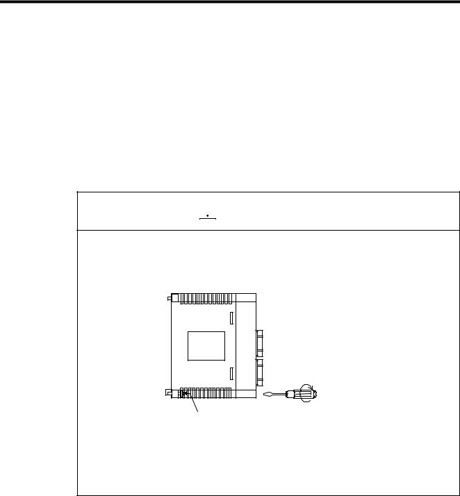
 Caution
•Firmly tighten the Module mounting screws and terminal block mounting screws to prevent them from loosening during operation.
Loose screws may result in a malfunction of the 260IF Module.
Unit mounting screws (M4 Phillips screws)
•Always turn OFF the power supply to the Module before installing it.
•Insert the connectors of the cables that are to be connected to the 260IF Module and secure them well.
Incorrect insertion of the connectors may result in a malfunction of the 260IF Module.
xi
Safety Precautions
Wiring


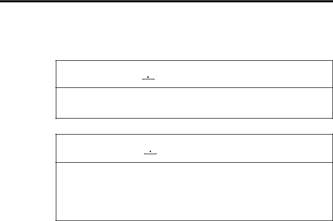
 Caution
•Always connect a power supply that meets the given specifications.
Connecting an inappropriate power supply may cause fires.
•Wiring must be performed by qualified personnel.
Incorrect wiring may cause fires, product failure, or malfunctions.
•Do not accidentally leave foreign matter such as wire chips in the Module when wiring.
This may cause fires, failures, and malfunctions.

 Mandatory
•Always ground the FG terminal to a ground resistance 100 Ω or less.
Failure to ground the 260IF Module may result in electrical shocks or malfunctioning.
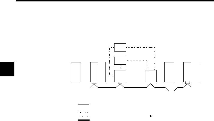
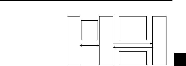
Select, separate, and lay external cables correctly.
•Consider the following items when selecting the I/O signal lines (external cables) to connect the 260IF Module to external devices.
•Mechanical strength
•Noise interference
•Wiring distance
•Signal voltage, etc.
•Separate the I/O signal lines from the power lines both inside and outside the control panel to reduce the influence of noise from the power lines.
If the I/O signal lines and power lines are not separated properly, malfunctioning may result.
Example of Separated External Cables
|
|
|
|
|
|
Steel separator |
|
|
|
|
|
|
|
|
|
|
|
|
|
|
|
|
|
|
|
|
|
|
|||
|
|
General |
|
|
|
|
|
Power |
|
control cir- |
|
|
Digital I/O |
|
|
circuit |
|
cuit cables |
|
|
signal |
|
|
cables |
|
|
|
|
cables |
|
|
|
|
|
|
|
|
|
|
|
|
|
|
|
|
|
|
xii
Application


 WARNING
•Do not touch any Module terminals when the system power is ON.
There is a risk of electrical shock.

 Caution
•Do not attempt to modify the 260IF Module programs, force outputs, switch between RUN and STOP, or performed other similar operations while the 260IF Module is operating without knowing the direct and indirect consequences of the operation.
Incorrect programming or operation may damage the equipment or cause an accident.
xiii

Safety Precautions
Maintenance


 WARNING
•Make sure that the polarity of the Module's built-in battery is correct. The battery must be installed correctly and must not be charged, disassembled, heated, thrown into fire, or short-circuited.
Improper handling may cause the battery to explode or ignite.
 Prohibited
•Do not attempt to disassemble or modify the 260IF Module in any way.
Doing so can cause fires, product failure, or malfunctions.
•The customer must not replace any built-in fuses.
If the customer replaces a built-in fuse, the 260IF Module may malfunction or break down. The built-in fuse must always be replaced by Yaskawa service staff.
xiv

General Precautions
Always note the following to ensure safe use.
•The 260IF Module was not designed or manufactured for use in devices or systems directly related to human life. Users who intend to use the product described in this manual for special purposes such as devices or systems relating to transportation, medical, space aviation, atomic power control, or underwater use must contact Yaskawa Electric Corporation beforehand.
•The 260IF Module has been manufactured under strict quality control guidelines. However, if this product is to be installed in any location in which a failure of the 260IF Module involves a life and death situation or in a facility where failure may cause a serious accident, safety devices MUST be installed to minimize the likelihood of any accident.
•Drawings in this manual show typical product examples that may differ somewhat from the product delivered.
•This manual may change without prior notice due to product improvements and specification changes or for easier use. We will update the manual number of the manual and issue revisions when changes are made. The revision number of the revised manual appears on the back of the manual.
•Contact your nearest Yaskawa sales representative or the dealer from whom you purchased the product and quote the manual number on the front page of the manual if you need to replace a manual that was lost or destroyed.
•Contact your nearest Yaskawa sales representative or the dealer from whom you purchased the product to order new nameplates whenever a nameplate becomes worn or damaged.
•Products modified by the customer are not covered by the Yaskawa warranty, nor does Yaskawa assume any liability for injury or damage that may result from such modifications.
xv

1 Outline
1 |
This chapter describes the DeviceNet Communications Interface (called the 260IF Module), an Option Module for MP900 Machine Controllers.
1.1 Outline of Configuration and Functions- - - - - - - - - - - - - - - - - 1-2
1.1.1 System Configuration - - - - - - - - - - - - - - - - - - - - - - - - - - - - - - - - - - - 1-2
1.1.2 Master Mode - - - - - - - - - - - - - - - - - - - - - - - - - - - - - - - - - - - - - - - - - 1-3
1.1.3 Slave Mode - - - - - - - - - - - - - - - - - - - - - - - - - - - - - - - - - - - - - - - - - - 1-4
1.1.4 Functional Outline- - - - - - - - - - - - - - - - - - - - - - - - - - - - - - - - - - - - - - 1-4
1-1

Outline
1.1.1System Configuration
1.1Outline of Configuration and Functions
1 |
The DeviceNet is a multivendor field network. DeviceNet specifications are controlled by the ODVA Open DeviceNet Vendor Association, Inc.).
The 260IF Module connects to a multivendor DeviceNet system and works as either a DeviceNet Master or Slave.
Refer to the DeviceNet specifications published by the ODVA for information on the DeviceNet.
1.1.1 System Configuration
The 260IF Module is a communications interface used to connect MP900 Machine Controllers to a DeviceNet network. Using the 260IF Module enables communications between MP900 Machine Controllers, other controllers, sensors, actuators, and other devices manufactured by other companies.
The 260IF Module can be connected to the DeviceNet as a Master or Slave.
|
MP920 Machine Controller |
|
|||||
PS-03 |
CPU- |
SVA-01 |
DI-01 |
DO-01 |
260IF |
|
Other company |
|
01 |
|
|
|
|
|
PLC |
|
|
|
|
|
|
|
|
|
|
|
|
|
|
|
|
Device Net
|
|
|
|
|
|
|
|
|
|
|
|
|
|
|
|
|
Sensor |
|
I/O device |
|
Other |
||
MP940D |
|
Other company |
|
|
|
|
|
devices |
|||
|
|
|
|
|
|
|
|
||||
|
|
|
|
|
|
|
|
|
|||
|
|
PLC |
|
|
|
|
|
|
|
|
|
|
|
|
|
|
|
|
|
|
|
|
|
Fig 1.1 System Configuration
Master/Slave
There are restrictions on the Machine Controller models that can be used as a Master or Slave.
Model |
Master |
Slave |
260IF Module Mounting |
|
Method |
||||
|
|
|
||
|
|
|
|
|
MP920 |
OK |
OK |
Option slot |
|
|
|
|
|
|
MP940 |
Not possible |
OK |
Built-in |
|
|
|
|
|
1-2

1.1 Outline of Configuration and Functions
1.1.2 Master Mode
There are two connection methods for Master Modes.
Multi-drop Connections
Internal I/O power supply
PS
External I/O power supply
PS
MP920 260IF
|
|
|
I/O |
|
|
|
I/O |
|
|
|
I/O |
|
|
|
|
|
|
|
|
|
|
|
|
|
|
|
|
|
|
|
|
|
|
|
|
|
|
|
1 |
|
|
|
|
|
|
|
|
|
|
|
|
|
|
|
|
|
|
|
|
|
Terminating |
|
|
|
|
|
|
|
|
|
|
|
|
|
|
|
Terminating resistance |
||||
resistance |
|
|
|
|
Trunk line |
|
|
|
|
|
|
|
|
|
121 Ω |
|||||
121 Ω |
|
|
|
|
|
|
|
|
|
|
|
|
|
Communications Power Sup- |
||||||
|
|
|
|
|
|
|
Drop line |
|
|
|
|
|
|
|
|
|
ply Tap (with reverse-current |
|||
|
|
|
|
|
|
|
External I/O power supply line |
|
|
|
|
|
|
|
prevention for multiple power |
|||||
|
|
|
|
|
|
|
|
|
|
|
|
|
|
supply units) |
||||||
|
|
|
|
|
|
|
Internal I/O power supply line |
|
|
|
|
|
|
|
||||||
|
|
|
|
|
|
|
|
|
|
|
|
|
|
|
|
|
||||
|
|
|
|
|
|
|
Communications power supply |
|
|
|
|
|
|
|
|
|
|
|
||
|
|
|
|
|
|
|
line |
|
|
PS |
|
|
Communications |
|||||||
|
|
|
|
|
|
|
|
|
|
|
|
|
|
|||||||
|
|
|
|
|
|
|
FG |
|
|
|
|
|
|
|
|
power supply |
||||
|
|
|
|
|
|
|
|
|
|
|
|
|
|
|
|
|
|
|||
T-branch, Multibranch, and Drop-line Branching Connections
MP920 |
260IF |
|
|
|
|
Trunk line |
|
|
|
|
|
|
Drop line |
|
|||
|
|
|
|
|
|
|
||
|
|
|
|
|
|
External I/O power supply line |
||
|
|
|
|
|
|
Internal I/O power supply line |
||
|
|
|
|
|
|
Communications power supply |
||
|
Terminating |
T-branch |
Multibranch Adaptor |
|
|
Communica- |
Terminating |
|
|
resistance |
Adaptor |
|
|
|
|
tions Power |
|
|
121 Ω |
|
|
|
|
|
Supply Tap |
resistance |
|
|
|
|
|
|
|
|
121 Ω |
|
I/O |
I/O |
I/O |
I/O |
I/O |
FG |
PS |
Communications |
|
|
|
|
|
|
|
power supply |
|
|
|
|
|
|
|
|
PS |
External |
|
|
|
|
|
|
|
I/O power supply |
|
|
|
|
|
|
|
|
|
|
|
|
|
|
|
|
|
PS |
Internal |
|
|
|
|
|
|
|
I/O power supply |
|
|
|
|
|
|
|
|
|
|
1-3
Outline
1.1.3 Slave Mode
1 |
1.1.3 Slave Mode
The following diagram shows the system configuration when the 260IF Module is used in Slave Mode.
|
PS |
Internal I/O power supply |
|
|
|
|
|
|
|
Master Mode |
External I/O power supply |
Slave Mode |
||
|
PS |
|
|
|
MP920 |
260IF |
|
MP920 |
260IF |
|
I/O |
I/O |
|
|
|
|
|
|
|
|
|
|
|
|
|
|
|
|
|
|
|
|
|
|
|
|
|
|
|
|
|
|
|
|
|
|
|
|
|
|
|
|
|
|
|
|
|
|
|
|
|
|
|
|
|
|
|
|
|
|
|
|
|
|
|
|
|
|
|
|
|
|
|
|
|
|
|
|
|
|
|
|
|
|
|
|
|
|
|
|
|
|
|
|
Terminating |
|
|
|
|
|
|
|
|
|
|
|
|
|
|
|
|
Terminating resistance |
||||||||||||
resistance |
|
|
|
|
|
|
|
|
|
|
|
|
|
|
|
|
121 Ω |
||||||||||||
121 Ω |
|
|
|
|
|
|
|
|
|
|
|
|
|
|
|
|
Communications Power |
||||||||||||
|
|
|
|
|
|
|
|
|
|
|
|
|
|
|
|
|
|
|
|
|
|
|
|
|
Supply Tap (with |
||||
|
|
|
|
|
Trunk line |
|
|
|
|
|
|
|
|
|
|
|
|
|
|
|
|
reverse-current preven- |
|||||||
|
|
|
|
|
|
|
|
|
|
|
|
|
|
|
|
|
|
|
|
||||||||||
|
|
|
|
|
Drop line |
|
|
|
|
|
|
|
|
|
|
|
|
|
|
|
|
tion for multiple power |
|||||||
|
|
|
|
|
External I/O power supply line |
|
|
|
|
|
|
|
|
|
|
|
|
|
|
|
|
supply units) |
|||||||
|
|
|
|
|
|
|
|
|
|
|
|
|
|
|
|
|
|
|
|
|
|
|
|
|
|
||||
|
|
|
|
|
Internal I/O power supply line |
|
|
|
|
|
|
|
|
|
|
PS |
|
|
Communications |
||||||||||
|
|
|
|
|
|
|
|
|
|
|
|
|
|
|
|
||||||||||||||
|
|
|
|
|
Communications power supply line |
FG |
|
|
|
|
|
|
|
|
|
|
|
|
|
|
power supply |
||||||||
|
|
|
|
|
|
|
|
|
|
|
|
|
|
|
|
|
|
||||||||||||
|
|
|
|
|
|
|
|
|
|
|
|
|
|
|
|
|
|
|
|
|
|
|
|
|
|
|
|
|
|
1.1.4 Functional Outline
I/O Communications
The I/O communications function uses DeviceNet I/O connections to exchange data between DeviceNet devices connected on the communications path and the MP900 Machine Controller.
The CP-717 Engineering Tool is used to allocate I/O registers in the Controller’s CPU for I/ O communications.
Message Communications
The message communications function sends explicit messages that read the DeviceNet device names or serial numbers and write parameters for DeviceNet devices.
The MSG-SND function is used for message communications.
1-4
1.1 Outline of Configuration and Functions
|
|
Explicit request mes- |
|
CPU |
|
sage |
|
Module |
MSG-SND |
Requested service code |
|
|
Class ID |
|
|
|
function |
Instance ID |
|
|
260IF |
Attribute ID |
|
|
(message data) |
DeviceNet |
|
|
(Device |
|
|
|
Net |
|
Slave |
|
Master) |
|
|
|
|
Explicit response mes- |
|
|
|
sage |
|
|
|
Response service code |
|
|
|
(message data) |
|
Fig 1.2 Message Communications Functions
1 |
Note: Message communications that use MSG-SND functions can be used when the 260IF Module is set as a DeviceNet Master.
1-5

2 Basic Specifications
This chapter describes the external appearance of the 260IF Module and the settings and display section specifications.
2.1 Specifications - - - - - - - - - - - - - - - - - - - - - - - - - - - - - - - - - - 2-2
2.2 External Appearance - - - - - - - - - - - - - - - - - - - - - - - - - - - - - 2-3
2.2.1 260IF Module - - - - - - - - - - - - - - - - - - - - - - - - - - - - - - - - - - - - - - - - - 2-3
2.3 Switch Specifications - - - - - - - - - - - - - - - - - - - - - - - - - - - - - 2-4
2.4 LED Indicator Specifications - - - - - - - - - - - - - - - - - - - - - - - - 2-5
2 |
2-1
Basic Specifications
2.1 Specifications
The basic specifications are given for the Interface Module in the following table.
2 |
|
Item |
Specifications |
|
|
|
|
|
Name |
|
260IF Module |
|
|
|
|
|
Model Number |
|
JEPMC-CM230 |
|
|
|
|
|
Circuit Number |
|
1 |
|
|
|
||
Applicable Communications Type |
I/O communications |
||
|
|
Explicit messages |
|
|
|
(Both conform to DeviceNet.) |
|
|
|
|
|
I/O Communi- |
Max. No. of Slaves |
63 nodes |
|
cations |
|
|
|
Max. I/O Bytes |
2048 bytes, 256 bytes/node |
||
|
|||
|
|
|
|
Message |
Max. No. of Nodes |
63 nodes. Simultaneous communications possible with up to 8 |
|
Communica- |
for Message |
nodes. |
|
tions |
Communications |
|
|
(Master Only) |
|
|
|
Max. Message |
256 bytes |
||
|
Length |
|
|
|
|
|
|
|
Function for |
MSG-SND |
|
|
Execution |
|
|
|
|
|
|
Switches for Settings |
Two rotary switches on the front: for node address |
||
|
|
DIP switch on the front: Baud rate |
|
|
|
Master/slave selection |
|
|
|
|
|
Indicators |
|
Two LED indicators: MS and NS |
|
|
|
||
Communications Power Supply |
24 VDC±10% (supplied from a special cable) |
||
Voltage |
|
|
|
|
|
||
Current Consumption |
Communications power supply: 45 mA max. (supplied from |
||
|
|
the communications connector) |
|
|
|
Internal circuit power supply (supplied from the PLC) |
|
|
|
|
|
Mass |
|
100 g |
|
|
|
||
Dimensions (mm) |
40 × 130 × 105 (W × H × D) |
||
|
|
|
|
2-2
2.2 External Appearance
2.2External Appearance
2.2.1260IF Module
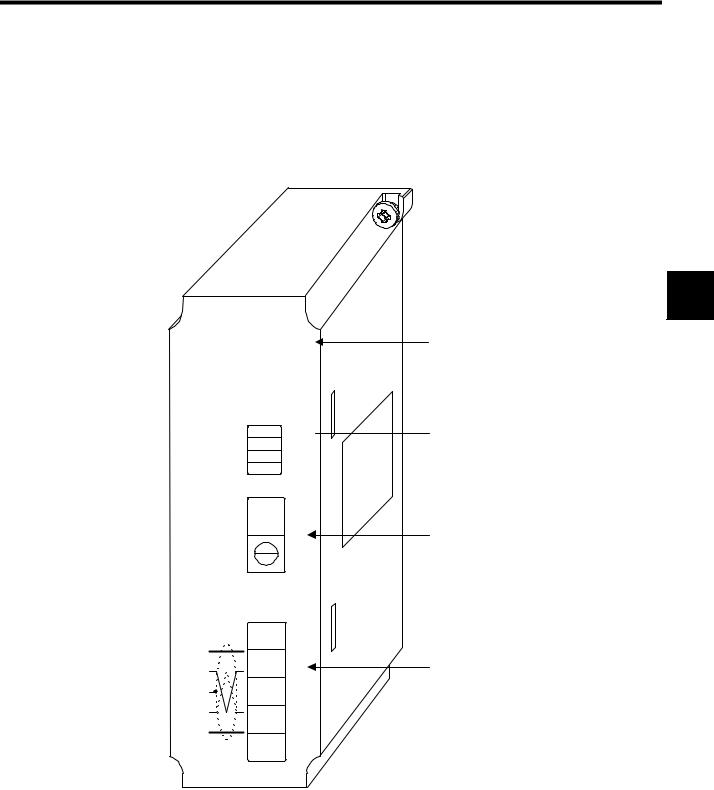
The external appearance of the 260IF Module is shown below.
260IF
MS 
 NS
NS
DR0
SW1 DR1
X1
X2
OFF ON
SW2  ×10
×10
SW3 ×1
2 |
MS: Module status (red/green light) NS: Network status (red/green light)
DIP Switch
DR0: Baud rate pin 0
DR1: Baud rate pin 1
X1: Master/slave setting
X2: Self-diagnosis
Node Address switches
SW2: 10’s digit
SW1: 1’s digit
CN1
DeviceNet connector
Fig 2.1 External Appearance of 260IF Module
2-3

Basic Specifications
2.2.1260IF Module
2.3Switch Specifications
Refer to 4.1 Basic Use of the 260IF Module for setting details.
SW1
2 |
The baud rate for DeviceNet communications and Slave/Master settings are made on this DIP switch.
Table 2.1 SW1 Specifications
Pin |
Meaning |
|
|
|
|
|
Setting |
|
|
|
|
|
|
|
|
|
|
DR0 |
DeviceNet |
|
|
|
|
|
|
|
|
DR1 |
|
DR0 |
|
|
|||
|
baud rate |
|
|
|
|
|||
|
|
|
|
|
|
|
|
|
|
|
|
OFF |
|
OFF |
125 kbps (default) |
|
|
|
|
|
|
|
|
|
|
|
DR1 |
|
|
OFF |
|
ON |
250 kbps |
|
|
|
|
|
|
|
|
|
|
|
|
|
|
ON |
|
OFF |
500 kbps |
|
|
|
|
|
|
|
|
|
|
|
|
|
|
ON |
|
ON |
(Do not change) |
|
|
|
|
|
|
|
|
|
|
|
|
|
|
|
|
|
|
||
X1 |
Slave/Master setting |
OFF |
|
Slave (default) |
|
|
||
|
|
|
|
|
|
|
||
|
|
ON |
|
Master |
|
|
||
|
|
|
|
|
|
|
||
X2 |
Not used |
Always OFF |
|
|
||||
|
|
|
|
|
|
|
|
|
SW2 and SW3
These rotary switches are used to set the DeviceNet MAC ID.
Table 2.2 SW2 and SW3 Specifications
Switch |
Meaning |
|
Setting |
|
|
|
|
|
|
*10 (SW2) |
MAC ID 10’s digit |
0 to 6 |
Set a two-digit local node MAC ID (0 to 63) in |
|
|
|
|
decimal using two rotary switches (default: 00). |
|
*1 (SW3) |
MAC ID 1’s digit |
0 to 9 |
||
|
||||
|
|
|
|
2-4
2.4 LED Indicator Specifications
2.4 LED Indicator Specifications
The LED indicator specifications for the 260IF Module are shown in the following table.
|
|
Table 2.3 |
LED Indicator Specifications |
|
|
|
|
|
|
Indicator |
Color |
Status |
|
Meaning |
|
|
|
|
|
MS |
Red/Green |
Not lit |
|
No power to the 260IF Module. |
|
|
Lit green |
|
Operating normally. |
|
|
Lit red |
|
Self-diagnostic error or WDT error. |
|
|
|
|
|
NS |
Red/green |
Not lit |
|
No power to the 260IF Module/offline.*1 |
|
|
Flashing green |
|
Online but not connected. |
|
|
Lit green |
|
Online and connected. |
|
|
Flashing red |
|
No-DeviceNet communications error. |
|
|
Lit red |
|
Communications not possible (duplicate MAC ID), |
|
|
|
|
bus-off error, or WDT error.*2 |
1. The 260IF Module is offline for the two seconds from the completion of the indicator test after startup through the completion of the MAC ID duplication check. The 260IF Module is online after the MAC ID duplication check at startup has been completed.
2. When the network power supply is OFF, the 260IF Module automatically resets as specified in the DeviceNet specifications even if a busoff error occurs. At the same time, the NS indicator will light red for a moment and then go OFF again immediately. After power has been restored to the network, the green NS indicator will start flashing (online but not connected).
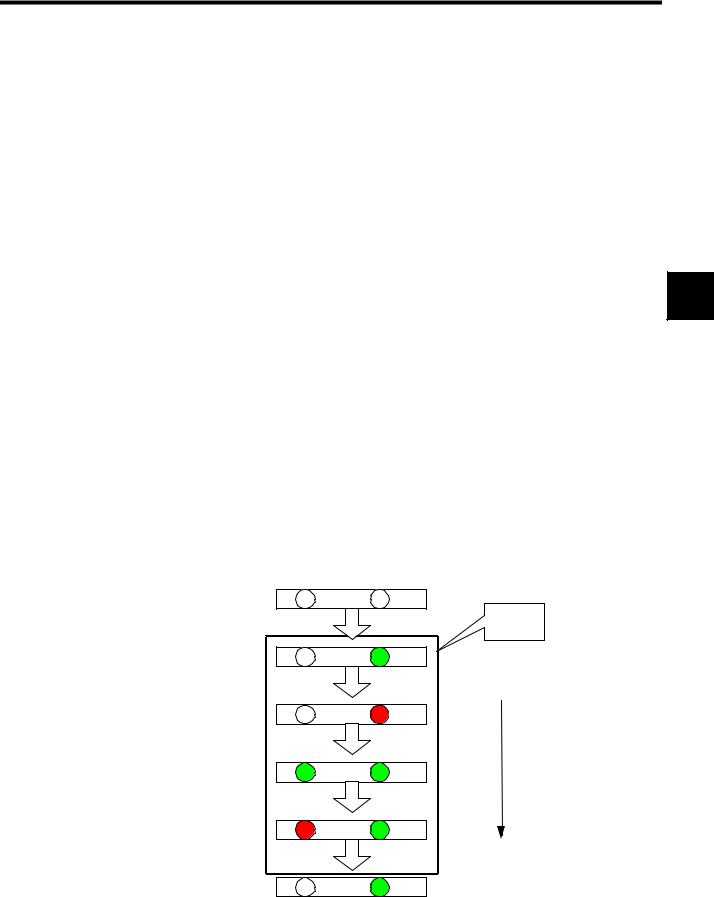
The following diagram shows the indicator test sequence that is performed immediately after the power is turned ON. Check the ON and OFF status of these indicators for any malfunctions. About 1 second is required for this test.
2 |
NS |
MS |
Power OFF |
Not lit |
OFF |
|
OFF |
|
|
|
Not lit |
|
|
|
Device |
|
|
startup |
OFF |
Green |
|
Not lit |
|
|
0.25 s |
Start of |
|
. |
s |
indicator test |
OFF |
R |
|
Not lit |
Red |
|
0.25 s |
|
|
. |
s |
|
Green |
Green |
1 s |
|
||
0..25s s |
|
|
R |
Green |
|
Red |
|
|
0.25 s |
End of |
|
. |
s |
indicator test |
|
|
|
Not lit |
Green |
|
OFF |
G |
|
Fig 2.2 Display during Indicator Test
2-5
Basic Specifications
2.2.1 260IF Module
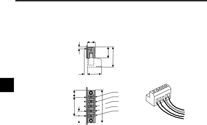
Connector Specifications
CN1 DeviceNet Connector Specifications
2 |
8.3
2
12 22
3.515
7.5 |
(7.62) |
|
|
5 |
V+ |
|
|
|
|
||
|
|
|
|
4 CAN_H |
|
20.32 |
|
(5.08) |
35.32 35.56 |
3 |
SHIELD |
5 |
1 V- |
||||
|
|
|
|
2 |
CAN_L |
|
|
|
|
|
|
|
|
|
5 |
|
|
5.08) |
|
|
|
|
|
|
Open Plug Conforming to |
|||||||
|
|
|||||||
|
( |
DeviceNet Specifications (5 |
||||||
pins, Male)
Connector on network side (Female)
Fig 2.3 CN1 Connectors
Table 2.4 CN1 Signal Names
Pin No. |
Signal |
I/O |
|
|
|
1 |
V |
I |
|
|
|
2 |
CAN_L |
I/O |
|
|
|
3 |
SHIELD |
_ |
|
|
|
4 |
CAN_H |
I/O |
|
|
|
5 |
V |
I |
|
|
|
5 V+ Red
4 CAN_H White
3 Drain Bare wire
2 CAN_L Blue
1 V- Black
2-6

3 Network Specifications
This chapter describes the network specifications and restrictions for the 260IF Module.
3.1 Network Configuration - - - - - - - - - - - - - - - - - - - - - - - - - - - - 3-2
3.1.1 Basic Network Configuration - - - - - - - - - - - - - - - - - - - - - - - - - - - - - - 3-2
3.1.2 Branching Methods- - - - - - - - - - - - - - - - - - - - - - - - - - - - - - - - - - - - - 3-3
3.1.3 Network Configuration Restrictions- - - - - - - - - - - - - - - - - - - - - - - - - - 3-6
3 |
3-1
Network Specifications
3.1.1Basic Network Configuration
3.1Network Configuration
This section outlines the network configuration.
3.1.1 Basic Network Configuration
Connection Methods
The following diagam shows an example network connection.
3 |
T (with terminating resistance) |
|
T |
|
T |
|
|
Terminating |
||||||||||||||||||
|
|
|
|
resistance |
|||||||||||||||||||||
|
|
|
|
|
|
|
|
|
|
|
|
|
|
|
|
|
|
|
|
|
|
|
|
|
|
|
|
|
|
|
|
|
|
|
|
|
|
|
|
|
|
|
|
|
Node |
|
Node |
|
|
|
|
|
|
|
|
|
|
|
|
|
|
|
|
|
T |
|
|
|
|
|
|
|
|
|
|
|
|
|
Node |
|
Node |
|
|
|
Node |
|
|
|
|
|
|
|
|
|
|
||||||||
|
|
|
|
|
|
|
|
|
|
|
|
|
|
|
|
|
|
||||||||
|
|
|
|
|
|
|
|
|
|
|
|
|
|
|
|
|
|
|
|
|
|
|
|
|
|
|
|
|
|
|
|
|
|
|
|
|
|
|
|
|
|
|
|
|
|
|
|
|
|
|
|
|
|
|
|
|
|
|
|
|
|
|
|
|
|
|
|
|
Node |
|
|
|
|
|
|
||
|
|
|
|
|
Trunk line |
|
|
|
|
|
|
|
|
|
|
|
|
|
|
|
|
|
|
|
|
|
|
|
|
|
|
|
|
|
|
|
|
|
|
|
|
|
|
|
|
|
|
|
|
||
|
|
|
|
|
Drop line |
|
|
|
|
|
|
|
|
|
|
|
|
|
|
|
|
|
|
|
|
|
|
T |
T-Branch Adapter |
|
|
|
|
|
|
|
|
|
|
|
|
|
|
||||||||
|
|
|
|
T |
|
|
|
|
|
|
|
|
|||||||||||||
|
|
|
|
|
|
|
|
|
|
|
|
|
|
|
|
|
|
|
|||||||
|
|
|
|
|
|
|
|
|
|
|
|
|
|
|
|
|
|
|
|
|
|
||||
|
|
|
|
|
|
|
|
|
|
|
|
|
|
|
|
|
|
|
|
|
|
|
|
|
|
|
|
|
|
|
|
|
|
|
|
|
Node |
|
|
|
|
Node |
|
|
|
|
|
|
|||
Fig 3.1 Network Connection
Configuration Elements
The network is configured from the following elements.
Nodes
A node is either a slave that connects to external I/O, or the Master, which manages the I/O of the slaves. There are no restrictions on the locations of the Master or Slaves. Any node in the figure above can be the Master or a Slave.
Trunk Line and Drop Lines
A cable with a terminator on each end is the trunk line. Any cable branching from the trunk line is a drop line.
Connection Methods
A node is connected using the T-branch method or multi-drop method. A T-Branch Adapter is used to connect a node with the T-branch method. A node is directly connected to the trunk line or a drop line with the multi-drop method. Both T-branch and multi-drop methods
3-2
3.1 Network Configuration
can be used together in the same network, as shown in the figure above.
Terminators
Both ends of the trunk line must connect to terminating resistance to decrease signal reflection and ensure stable network communications.
Communications Power Supply
The communications connectors of each node must be provided with communications power supply through the communications cable for DeviceNet communications. Communications power supply, internal circuit power supply, and I/O power supply must all be provided separately.
INFO |
1 Use only DeviceNet cables as communications cables.
2 Always connect terminators to both ends of the trunk line.
3 Do not connect lightning arresters or any devices to the network other than the 260IF Module and DeviceNet-conforming products.
3 |
3.1.2 Branching Methods
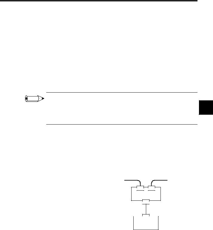
Branching from the Trunk Line
There are three methods that can be used to branch from the trunk line.
Branching to One Drop Line
Trunk line |
Trunk line |
|
T-Branch Adapter |
|
Drop line |
|
Node |
3-3
Network Specifications
3.1.2 Branching Methods
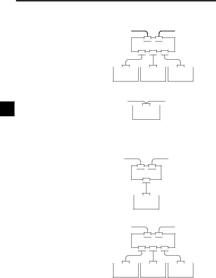
3 |
Branching to Three Drop Lines
Trunk line |
|
Trunk line |
|
|
T-Branch |
|
|
Adapter |
Drop line |
Drop line |
Drop line |
|
|
|
Node |
Node |
Node |
Direct Node Connection
Trunk line |
Multi-drop method |
Trunk line |
|
Node
Branching from Drop Lines
There are three methods that can be used to branch from drop lines.
Branching to One Drop Line
Drop line |
Drop line |
T-Branch
Adapter
Drop line
Node
Branching to Three Drop Lines
Drop line |
|
Drop line |
|
|
T-Branch |
|
|
Adapter |
Drop line |
|
Drop line |
|
Drop line |
|
Node |
Node |
Node |
3-4 |
|
|
Loading...