


Operator’s Manual
Snow Thrower
Model 611
IMPORTANT: Read safety rules and instructions carefully before operating equipment.
Warning: This unit is equipped with an internal combustion engine and should not be used on or near any unimproved forestcovered, brush-covered or grass-covered land unless the engine’s exhaust system is equipped with a spark arrester meeting applicable local or state laws (if any). If a spark arrester is used, it should be maintained in effective working order by the operator. In the State of California the above is required by law (Section 4442 of the California Public Resources Code). Other states may have similar laws. Federal laws apply on federal lands. A spark arrester for the muffler is available through your nearest engine authorized service dealer or contact the service department, P.O. Box 368022 Cleveland, Ohio 44136-9722.
MTD PRODUCTS INC. P.O. BOX 368022 CLEVELAND, OHIO 44136-9722
PRINTED IN U.S.A. |
FORM NO.770-10001B.fm |
ECO No.1222 |
(6/2000) |
TABLE OF CONTENTS |
|
Content |
Page |
Important Safe Operation Practices................................................................... |
3 |
Hardware Pack .................................................................................................. |
5 |
Assembling Your Snow Thrower........................................................................ |
6 |
Know Your Snow Thrower ................................................................................. |
11 |
Operating Your Snow Thrower........................................................................... |
12 |
Making Adjustments .......................................................................................... |
13 |
Maintaining Your Snow Thrower ........................................................................ |
15 |
Service............................................................................................................... |
16 |
Off-Season Storage ........................................................................................... |
18 |
Troubleshooting................................................................................................. |
19 |
Parts List............................................................................................................ |
20 |
FINDING MODEL NUMBER
This Operator’s Manual is an important part of your new snow thrower. It will help you assemble, prepare and maintain the unit for best performance. Please read and understand what it says.
Before you start assembling your new equipment, please locate the model plate on the equipment and copy the information from it in the space provided below. The information on the model plate is very important if you need help from our Customer Support Department or an authorized dealer.
•You can locate the model number by standing behind the unit in the operating position and looking down at the frame below engine. A sample model plate is explained below. For future reference, please copy the model number and the serial number of the equipment in the space below.
(Model Number) |
|
(Serial Number) |
Copy the model number here: |
|
|
|
|||
|
|
|
|
|
|
|
|
|
Copy the serial number here: |
|
MTD PRODUCTS INC |
|
||
CLEVELAND, OHIO 44136 |
|
|||
CALLING CUSTOMER SUPPORT
If you have difficulty assembling this product or have any questions regarding the controls, operation or maintenance of this unit, please call Customer Support Department.
Call 1- (330) 220-4MTD (4683) or 1- (800)-800-7310 to reach a Customer Support representative. Please have your unit’s model number and serial number ready when you call. See previous section to locate this information. You will be asked to enter the serial number in order to process your call .
For more details about your machine, visit our web site at www.mtdproducts.com
2

SECTION 1: IMPORTANT SAFE OPERATION PRACTICES
This symbol points out important safety instructions which, if not followed, could endanger the personal safety and/or property of yourself and others. Read and follow all instructions in this manual before attempting to operate this machine. Failure to comply with these instructions may result in personal injury. When you see this symbol— heed its warning.
WARNING: Engine Exhaust, some of its constituents, and certain vehicle components contain or emit chemicals known to State of California to cause cancer and birth defects or other reproductive harm.
DANGER: This machine was built to be operated according to the rules for safe operation in this manual. As with any type of power equipment, carelessness or error on the part of the operator can result in serious injury. This machine is capable of amputating hands and feet and throwing objects. Failure to observe the following safety instructions could result in serious injury or death.
Training
1.Read, understand, and follow all instructions on the machine and in the manual(s) before attempting to assemble and operate. Keep this manual in a safe place for future and regular reference and for ordering replacement parts.
2.Be familiar with all controls and their proper operation. Know how to stop the machine and disengage them quickly.
3.Never allow children under 14 years old to operate this machine. Children 14 years old and over should read and understand the operation instructions and safety rules in this manual and should be trained and supervised by a parent.
4.Never allow adults to operate this machine without proper instruction.
5.Thrown objects can cause serious personal injury. Plan your snow throwing pattern to avoid discharge of material toward roads, bystanders and the like.
6.Keep bystanders, helpers, pets and children at least 75 feet from the machine while it is in operation. Stop machine if anyone enters the area.
7.Exercise caution to avoid slipping or falling, especially when operating in reverse.
Preparation
1.Thoroughly inspect the area where the equipment is to be used. Remove all door mats, newspapers, sleds, boards, wires and other foreign objects which could be tripped over or thrown by the auger/impeller.
2.Always wear safety glasses or eye shields during operation and while performing an adjustment or repair to protect your eyes. Thrown objects which ricochet can cause serious injury to the eyes.
3.Do not operate without wearing adequate winter outer garments. Do not wear jewelry, long scarves or other loose clothing which could become entangled in moving parts. Wear footwear which will improve footing on slippery surfaces.
4.Use a grounded three wire extension cord and receptacle for all units with electric start engines.
5.Adjust collector housing height to clear gravel or crushed rock surfaces.
6.Disengage all clutch levers before starting the engine.
7.Never attempt to make any adjustments while engine is running, except where specifically recommended in the operator’s manual.
8.Let engine and machine adjust to outdoor temperature before starting to clear snow.
9.To avoid personal injury or property damage use extreme care in handling gasoline. Gasoline is extremely flammable and the vapors are explosive. Serious personal injury can occur when gasoline is spilled on yourself or your clothes which can ignite. Wash your skin and change clothes immediately.
a.Use only an approved gasoline container.
b.Extinguish all cigarettes, cigars, pipes and other sources of ignition.
c.Never fuel machine indoors.
d.Never remove gas cap or add fuel while the engine is hot or running.
e.Allow engine to cool at least two minutes before refueling.
f.Never over fill fuel tank. Fill tank to no more than ½ inch below bottom of filler neck to provide space for fuel expansion.
g.Replace gasoline cap and tighten securely.
h.If gasoline is spilled, wipe it off the engine and equipment. Move machine to another area. Wait 5 minutes before starting the engine.
i.Never store the machine or fuel container inside where there is an open flame, spark or pilot light (e.g. furnace, water heater, space heater, clothes dryer etc.).
j.Allow machine to cool at least 5 minutes before storing.
Operation
1.Do not put hands or feet near rotating parts, in the auger/ impeller housing or discharge chute. Contact with the rotating parts can amputate hands and feet.
2.The auger/impeller clutch lever is a safety device. Never bypass its operation. Doing so, makes the machine unsafe and may cause personal injury.
3.The clutch levers must operate easily in both directions and automatically return to the disengaged position when released.
4.Never operate with a missing or damaged discharge
3
chute. Keep all safety devices in place and working.
5.Never run an engine indoors or in a poorly ventilated area. Engine exhaust contains carbon monoxide, an odorless and deadly gas.
6.Do not operate machine while under the influence of alcohol or drugs.
7.Muffler and engine become hot and can cause a burn. Do not touch.
8.Exercise extreme caution when operating on or crossing gravel surfaces. Stay alert for hidden hazards or traffic.
9.Exercise caution when changing direction and while operating on slopes.
10.Plan your snow throwing pattern to avoid discharge towards windows, walls, cars etc. To avoid property damage or personal injury caused by a ricochet.
11.Never direct discharge at children, bystanders and pets or allow anyone in front of the machine.
12.Do not overload machine capacity by attempting to clear snow at too fast of a rate.
13.Never operate this machine without good visibility or light. Always be sure of your footing and keep a firm hold on the handles. Walk, never run.
14.Disengage power to the auger/impeller when transporting or not in use.
15.Never operate machine at high transport speeds on slippery surfaces. Look down and behind and use care when in reverse.
16.If the machine should start to vibrate abnormally, stop the engine, disconnect the spark plug and ground it against the engine. Inspect thoroughly for damage. Repair any damage before starting and operating.
17.Disengage all clutch levers and stop engine before you leave the operating position (behind the handles). Wait until the auger/impeller comes to a complete stop before unclogging the discharge chute, making any adjustments, or inspections.
18.Never put your hand in the discharge or collector openings. Always use a clearing tool to unclog the discharge opening.
19.Use only attachments and accessories approved by the manufacturer (e.g. wheel weights, tire chains, cabs etc.).
20.If situations occur which are not covered in this manual, use care and good judgment. Contact your dealer or telephone 1-800-800-7310 for assistance and the name of your nearest servicing dealer.
Maintenance And Storage
1.Never tamper with safety devices. Check their proper operation regularly.
2.Disengage all clutch levers and stop engine. Wait until the auger/impeller come to a complete stop. Disconnect the spark plug wire and ground against the engine to prevent unintended starting before cleaning, repairing, or inspecting.
3.Check bolts, and screws for proper tightness at frequent intervals to keep the machine in safe working condition. Also, visually inspect machine for any damage.
4.Do not change the engine governor setting or over-speed the engine. The governor controls the maximum safe operating speed of the engine.
5.Snow thrower shave plates and skid shoes are subject to wear and damage. For your safety protection, frequently check all components and replace with original equipment manufacturer’s (O.E.M.) parts only. “Use of parts which do not meet the original equipment specifications may lead to improper performance and compromise safety!”
6.Check clutch controls periodically to verify they engage and disengage properly and adjust, if necessary. Refer to the adjustment section in this operator’s manual for instructions.
7.Maintain or replace safety and instruction labels, as necessary.
8.Observe proper disposal laws and regulations for gas, oil, etc. to protect the environment.
9.Prior to storing, run machine a few minutes to clear snow from machine and prevent freeze up of auger/impeller.
10.Never store the machine or fuel container inside where there is an open flame, spark or pilot light such as a water heater, furnace ,clothes dryer etc.
11.Always refer to the operator’s manual for proper instructions on off-season storage.
Your Responsibility:
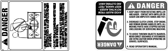
Restrict the use of this power machine to persons who read, understand and follow the warnings and instructions in this manual and on the machine. The safety labels are given below for your reference.
4
SECTION 2: CONTENTS OF HARDWARE PACK
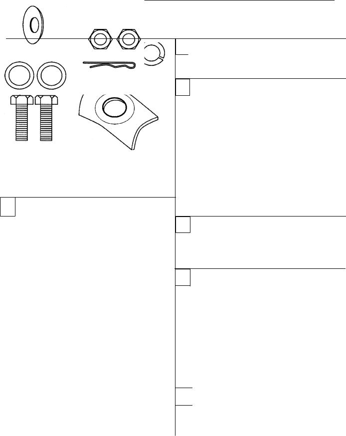
Lay out the hardware according to the illustration below for identification purposes. Part numbers are shown in parentheses. (Hardware pack may contain extra items which are not used on your unit.)
A |
|
(4)Lock Washers (C) |
(2)Hex Bolts (A) |
(736-0119) |
|
|
(710-3180) |
|
(2) Hex Bolts (B) |
(2) Saddle (I) |
|
710-3008 |
||
(784-5599) |
||
|
D
|
|
(4) Self-Tapping |
|
|
Screws (F) |
|
|
(710-0599) |
|
(2) Hex |
|
|
Bolts (G) |
|
(710-3015) |
(2) Hex Lock Nuts (H) |
|
|
|
(712-3027) |
|
|
|
G |
|
(2) Hex Nuts (D) |
|
|
(712-3010) |
|
Cupped Washer (N) |
|
(736-0242) |
|
|
|
|
Hairpin Clip (T) |
|
|
(714-0104) |
|
(2) Flat Washers (S) |
|
(736-0185) |
|
|
B |
|
(4) Hex Nuts (D) |
|
(712-3010) |
|
|
C
(4) Carriage Bolts (E)
(710-0262)
(4) Lock
Washers (C)
(4) Hex Nuts (D) (736-0119)
(712-3010)
E
(2)“Z” Fitting (R) (746-0778)
(2) Hex Nuts (J)
(712-0121)
F
|
|
(6) Hex Lock Nuts (M) |
|
|
|
(712-3027) |
|
|
(6) Hex Bolts (K) |
(3) Chute Flange Keepers |
|
|
(710-3015) |
||
|
(Not Shown) (731-0851) |
||
|
|
||
|
|
|
|
H |
|
(2) Shear Bolts |
|
(2) Hex Lock Nuts |
(710-0890A) |
||
* |
|||
|
(712-0429) |
|
|
|
|
*The augers are secured to the spiral shaft with two shear bolts and hex lock nuts. If you hit a hard foreign object or an ice jam, the snow thrower is designed so that the bolts may shear. Two replacement shear bolts and nuts are provided for your convenience. Store in a safe place until needed.
5
SECTION 3: ASSEMBLING YOUR SNOW THROWER
IMPORTANT: After assembly, service engine with gasoline, and check oil level as instructed in the separate engine manual packed with your unit.
NOTE: References to right or left side of the snow thrower are determined from behind the unit in the operating position.
Unpacking
•Remove staples or break glue on top flaps of the carton. Remove any loose parts included with unit (i.e., operator’s manual, etc.).
•Cut corners of the carton and lay ends down flat. Remove packing material.
•Roll unit out of carton. Check carton thoroughly for loose parts before discarding.
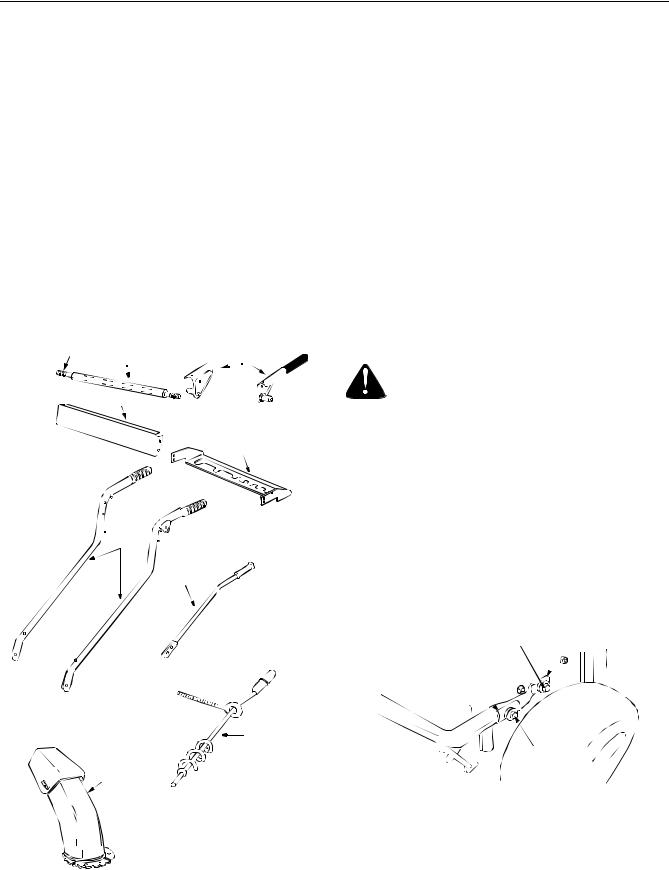
•Compare Figure 1 with the list below to identify loose parts in the carton.
Ref. |
Description |
Qty. |
A |
Handles (Right and Left) |
2 |
B |
Pivot Rod |
1 |
C |
Cover Tube |
1 |
D |
Clutch Grips (Right and Left) |
2 |
E |
Handle Panel |
1 |
F |
Speed Selector Plate |
1 |
G |
Shift Lever |
1 |
H |
Chute Directional Control Assembly |
1 |
J |
Chute Assembly |
1 |
I |
Hardware Pack |
1 |
Tools Required
1. Two adjustable wrenches
Loose Parts In Carton
 B C
B C 
 D
D
E
F
A
G
H
J
Figure 1
Before Assembly
WARNING: Disconnect the spark plug wire and ground it against the engine to prevent unintended starting.
Attaching Handles
(Use Hardware Group A.)
•Place right handle in position against the snow thrower so that the flat side of the handle is against the frame. Align the bottom hole on the handle to the corresponding hole on the snow thrower housing.
•Insert hex bolt (B) and lock washer (C) through these holes to secure the handle to the snow thrower housing. See Figure 2. There are weld nuts welded to the inside of the frame for these bolts. Do not tighten now.
Hex Bolt B |
Lock Washer C |
Saddle
Washer I
Hex Bolt A,
Lock Washer C
Figure 2
•Attach the left handle in the same manner. Do not tighten now.
•Place saddle washer (I) over upper holes on handles as shown in Figure 2. Secure to the frame with lock washers (C) and hex bolts (A). Do not tighten now.
6
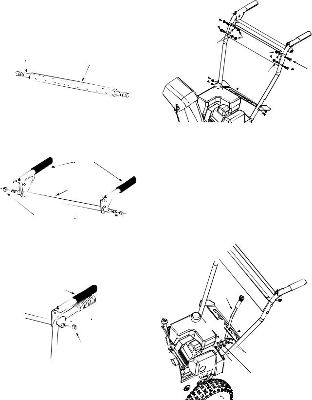
Attaching Clutch Grips
(Use Hardware Group B.)
•Slide the pivot rod into the cover tube as shown in Figure 3.
NOTE: In some models, the pivot rod and cover tube may be pre-assembled.
Pivot Rod
Cover Tube
Carriage
Bolts E
Lock
Washer C
Self-Tapping
Screws F
|
H |
|
|
|
|
|
|
e |
|
|
|
|
|
|
x N |
|
|
|
|
|
|
|
ut |
|
|
|
|
|
|
s |
|
|
|
|
Speed |
D |
|
|
|
|
|
|
|
|
|
|
||
Selector |
|
|
|
|
|
|
Plate |
Lock |
|
|
|
|
|
|
|
|
|
|
|
|
|
Washer C |
Carriage |
|
|
||
|
||||||
|
|
|
Bolts E |
|||
|
|
|
||||
Figure 3
•Place the clutch grips in position on the rod as shown in Figure 4. Thread hex nuts (D) onto each end of the rod. Tighten nuts allowing the clutch grips to move freely on the pivot rod. See Figure 4.
Clutch
Grips 
Pivot Rod
with Cover
Hex Nuts D
Figure 4
•Insert clutch grip and rod assembly into handle tabs. Clutch grips must sit on top of the handles. Thread hex nuts (D) on each end to hold into position. Do not tighten. See Figure 5.
Clutch Grip and
Rod Assembly
Handle

 Tab
Tab
Hex Nut D
Figure 5
Attaching Handle Panel
(Use Hardware C.)
•Position the handle panel between handles. Insert two carriage bolts (E) on each side and secure with lock washers (C) and hex nuts (D). See Figure 6.


 Self-Tapping
Screws F
Figure 6
Attaching Speed Selector Plate
(Use Hardware D.)
•Assemble the speed selector plate to the outside of the handles as shown in Figure 6. Secure using two self-tapping screws (F) on each side.
Attaching Shift Lever
•Insert the shift lever through slot in the speed selector plate. See Figure 7.
NOTE: The bend in the lever should be towards the operator.
Shift
Lever
Hex |
|
|
|
||
Bolt |
G |
|
|
Speed Selector |
|
|
|
|
|
|
Plate |
|
|
|
|||
|
|
|
|
Hex Lock Nuts H |
|
|
|
|
Hex |
||
|
|
|
Bolt G |
||
|
|
|
|
Shift Lever |
|
|
|
|
|
Spring |
|
|
|
|
|
|
|
Figure 7
•Secure shift lever to the shift lever spring using two hex bolts (G) and hex lock nuts (H). Tighten both
7
bolts finger tight. At this point the shift lever and shift lever spring are not against each other. As you tighten the bolts and nuts with two wrenches, these will pull together. See Figure 7.
•Tighten all hardware assembled to this point. Make sure that clutch grips are moving freely.
Attaching Control Cables
(Use Hardware E.)
•Thread hex nuts (J) onto the “Z” fittings (R). Insert “Z” fitting into hole in clutch grips. See Figure 8.
•Route the left cable between engine and speed selector plate and then between handle panel and clutch lever pivot rod before threading onto the left “Z” fitting.
•Assemble the right cable in the same manner.
•Both cables should have minimal slack, but not tight. Tighten or loosen hex nuts on the “Z” fitting to adjust.
“Z” Fitting R
Clutch
Grip
Pivot
 Rod
Rod
Hex Nut J
Handle
 Panel
Panel
Figure 8
IMPORTANT: If the right hand lock-out cable is not adjusted correctly, wheels will tend to turn. If the left hand lock-out cable is not adjusted correctly, the augers will keep on rotating.
IMPORTANT:Please note that the drive clutch cable on units with 16” wheels is routed under the axle. In other units, the cable is routed over the axle.
WARNING: Do not over-tighten the clutch cables. Tension on either cable in the disengaged (up) position may override the safety features of the machine.
Attaching Chute Assembly
(Use Hardware Group F.)
•Place chute assembly over chute opening, with the opening in the chute assembly facing the front of the unit.
•Place chute flange keepers beneath lip of chute assembly, with the flat side of chute flange keeper facing downward. See Figure 9.
Chute
Assembly
Hex Bolt K
Hex Lock Nut M
Chute Flange
Keeper
Figure 9
•Insert hex bolt (K) up through chute flange keeper and chute assembly as shown in Figure 9. Secure with hex lock nut (M). After assembling all three chute flange keepers, tighten all nuts and bolts securely. Do not over-tighten.
NOTE: Lock nuts cannot be threaded onto a bolt by hand. Tighten with two 7/16” or adjustable wrenches.
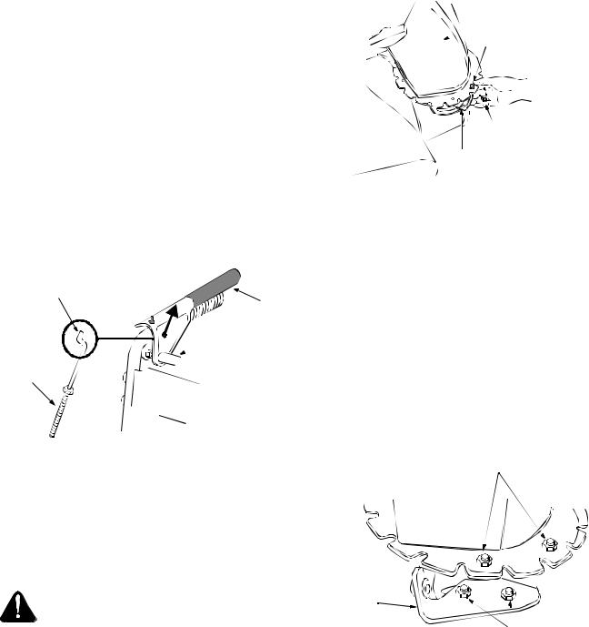
Attaching Chute Directional Control
(Use Hardware Group G.)
•Loosen the two hex nuts which secure the lower chute directional control support bracket (see Figure 10) to the snow thrower housing.
Hex Bolts K
Hex Lock Nuts M
Lower
Chute
Directional
Control
Bracket |
Hex Nuts |
|
Figure 10
•Place one flat washer (T) over the end of the chute directional control, then insert the end of the chute directional control into the hole in the plastic bushing on the chute bracket. See Figure 11. Place second flat washer (T) on chute directional control, and secure with hairpin clip (S).
8

Flat |
Chute |
Washers T |
Directional |
|
Control |
Hairpin Clip S
Chute Directional Control
Bracket
Figure 11
•Thread one hex nut (D) onto the eyebolt on the chute directional control assembly until there is at least two inches of threads showing between the nut and the eyebolt head. See Figure 12 inset.
•Place the eyebolt into the hole located half way up the left handle. See Figure 12. Secure with cupped washer (N) and hex nut (D) making sure that the cupped side of the washer is against the handle.
2” of thread |
Cupped
Washer N


 Hex Nut D
Eye Bolt
Hex Nut D
Chute
Directional
Control
Figure 12
•Adjust the chute directional control bracket so that the spiral on the chute directional control fully engages the teeth on the chute assembly. See Figure 14. Tighten all hardware.
Spiral should engage teeth of chute here
Figure 13
•Check to make sure all nuts and bolts on the control panel and all four bolts which secure the handles to the frame are tight.
Final Assembly & Adjustments
Auger Control
•To check the adjustment of the auger control, push forward on the left hand clutch grip (depress the rubber bumper). There should be slack in the cable. Release the clutch grip. The cable should be straight. Make certain you can depress the auger control grip against the left handle completely.
•If necessary, loosen the hex lock nut and thread the cable in (for less slack) or out (for more slack) as necessary. Refer to Figure 14.
•Tighten the lock nut against the cable when correct adjustment is reached.
“Z” Fitting
Hex Bolt
Cable


Figure 14
9
 Loading...