


future better a build We
YANMAR 4TNV, Elec.Control.Governor (Tier III)
ENGINE TRAINING |
EDITOR |
for R55-7A, R55W-7A, R80-7A |
PIETER EVERAERTS |
R55-9, R55W-9, R60CR-9, R80CR-9
aug. 2012

CONTENT
|
PAGE |
|
|
1] GENERAL |
03 |
|
|
2] ELECTRONIC CONTROL SYSTEM (ECO) |
06 |
|
|
3] INJECTION PUMP |
10 |
4] EXHAUST GAS RECIRCULATION (EGR) |
43 |
|
|
5] COOLANT TEMP SENSOR |
45 |
|
|
6] ELECTRICS |
47 |
|
|
7] ENGINE VIEW |
51 |
|
|
8] ENGINE ERROR CODE SYSTEM |
52 |
9] YANMAR DIAGNOSTIC TOOL |
58 |
|
|
10] FUEL PUMP ADJUSTMENT & &REPLACEMENT |
61 |
|
|
Related manuals: |
|
TNV-ECO-manual.pdf |
(>Ceres : TNV-SERIES-ECM, part 1) |
TNV-ECO-diagnostic tool.pdf (>Ceres : TNV-SERIES-ECM, part 2)
TNV-ECO-troubleshooting.pdf
TNV-INJ-mechanical.pdf (>Ceres: YANMAR FUEL INJECTION)
TNV-service-mechanical.pdf (>Ceres: YANMAR 3TNV, 4TNV)
PAGE
- 2 -
Hyundai Heavy Industries Europe |
Arranged by Pieter Everaerts |
Vossendaal 11 |
Instructor HHIE |
2440 Geel - Belgium |
Tel 0032 (0)14 56 22 44 |
Tel 0032 (0)14 56 22 00 |
Fax 0032 (0)14 56 22 65 |
Fax 0032 (0)14 56 22 65 |
|
|
|
HHIE TRAINING CENTRE
1. GENERAL - OVERVIEW |
PAGE |
|
- 3 - |
|
|
|
|
(All listed engines are Yanmar "NV3-Series engines" >> Range 3000...4000cc: all direct injection)
YANMAR |
|
R55(W)-7 |
R80-7 |
|
R55(W)-7A |
R80-7A |
|||
|
|
|
|
|
|
|
|
||
|
|
|
# cyl |
|
|
derating output |
standard output |
||
Engine model |
|
4TNV94L |
cyl bore (mm) |
4TNV98 |
|
4TNV98-EPHYB |
eco -eng.) |
4TNV98-ZVHYB |
eco -eng.) |
|
|
|
|
|
|||||
Content / HP (Rated Gross) at rpm |
|
3054cc / 53HP at 2200 rpm |
3318cc / 60HP at 2100 rpm |
|
3319cc / 57HP at 2400 rpm |
3319cc / 59.6HP at 2100 rpm |
|||
Max. Torque at RPM |
|
20.6 kgf at 1400 rpm |
25.2 kgf at 1000 rpm |
|
20.5 kgf at 1550 rpm |
24.5 kgf at 1000 rpm |
|||
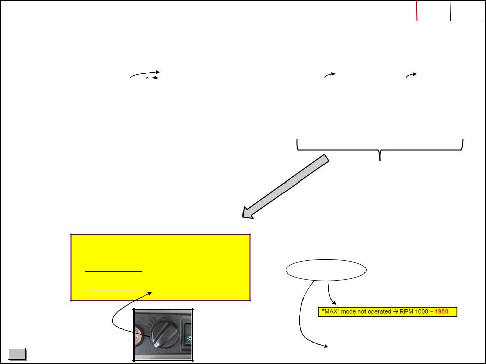
SETTING MAX RPM |
|
2300±50 (R55-7) |
2250±50 |
|
2260±50 |
|
2250±50 |
|
|
|
|
2400±50 (R55W-7) |
|
|
("M" mode selected) |
("H" mode selected) |
|||
|
|
|
|
|
|
|
|
|
|
-7A "adapted technologie" to meet Tier III
(higher fuel injection pressure)
Electric Control of Exhaust Gas Regulation
Electric Control of Governor (= "ECO")
|
Explanation of engine model names (-7A/-9) |
||||
|
|
|
|
||
|
|
E or Z stands for kind of output |
|
||
|
|
P, V |
rated eng. speed |
|
|
|
|
HY |
Hyundai |
|
|
|
|
B |
excavator |
|
|
|
-9 Series same engines |
||||
|
High idle |
Low idle |
eng. type |
||
|
(M mode) |
|
|
|
|
R55-9 |
2200±30 |
1000±30 |
4NTV98-EPHYBU |
||
R55W-9 |
2200±50 |
1050±100 |
4NTV98-EPHYBU |
||
R60CR-9 |
2200±50 |
1000±50 |
4NTV98-EPHYBU |
||
R80CR-9 |
2100±50 |
1000±50 |
4NTV98-ZVHYB |
||
|
|
|
|
|
|
C |
HHIE TRAINING CENTRE |
|
At full charge,
eng. drop is max “150 rpm”

1. GENERAL - SPECIFICATION |
PAGE |
|
- 4 - |
|
|
|
|
R55(W)-7A R80-7A
2260 |
2250 |
C |
HHIE TRAINING CENTRE |
|
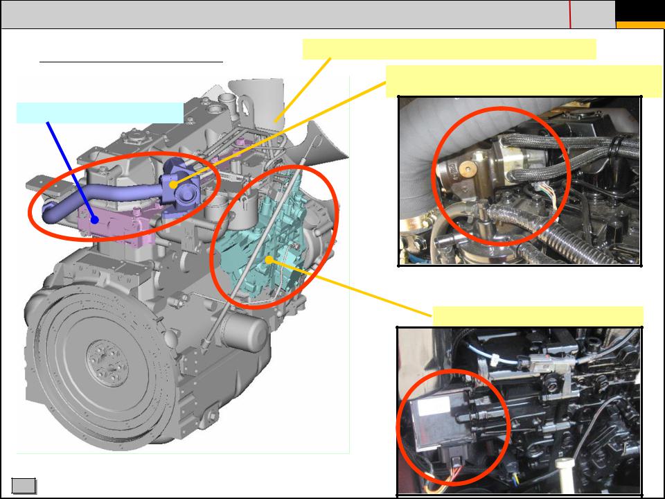
1. GENERAL - ENGINE LAY-OUT
NV3, adapted (tier III)
Cylinder head with 4 valves
PAGE
- 5 -
Optimization of injection bore diameter→Reduce PM
Electronic control of EGR (exhaust gas recirculation) to achieve lower NOx
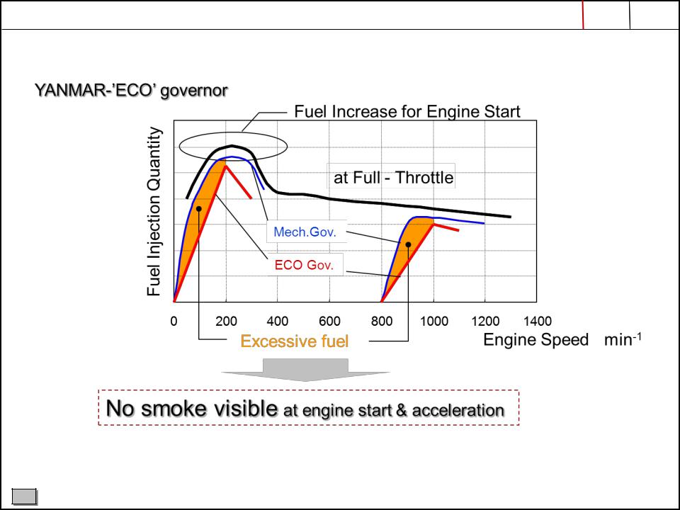
Electronic Control of Governor (ECO)
C |
HHIE TRAINING CENTRE |
|
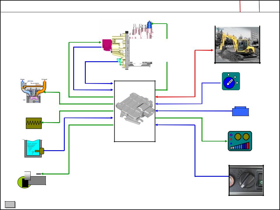
2. ELECTRONIC CONTROL SYSTEM (ECO) |
PAGE |
|
- 6 - |
|
|
|
|
Electronic |
CSD valve (cold start device) |
|
control |
|
|
|
|
|
governor |
|
|
|
|
|
Actuator |
Fuel |
|
|
|
CAN |
||
Rack position |
injection pump |
||
|
|||
sensor |
|
|
|
Engine speed sensor |
|
||
|
|
OFF |
|
|
|
ON |
|
|
ECU |
START |
|
|
|
||
|
|
Key switch |
|
EGR
Switch
Air heater
Display
Coolant temp. sensor
Starter
Accelerator
C |
HHIE TRAINING CENTRE |
|
2. ELECTRONIC CONTROL SYSTEM ECO GOVERNOR |
PAGE |
|
- 7 - |
|
|
|
|
C |
HHIE TRAINING CENTRE |
|
2. ELECTRONIC CONTROL SYSTEM ECO GOVERNOR |
PAGE |
|
- 8 - |
|
|
|
|
C |
HHIE TRAINING CENTRE |
|
2. ELECTRONIC CONTROL SYSTEM 2G ECO GOVERNOR |
PAGE |
|
- 9 - |
|
|
|
|
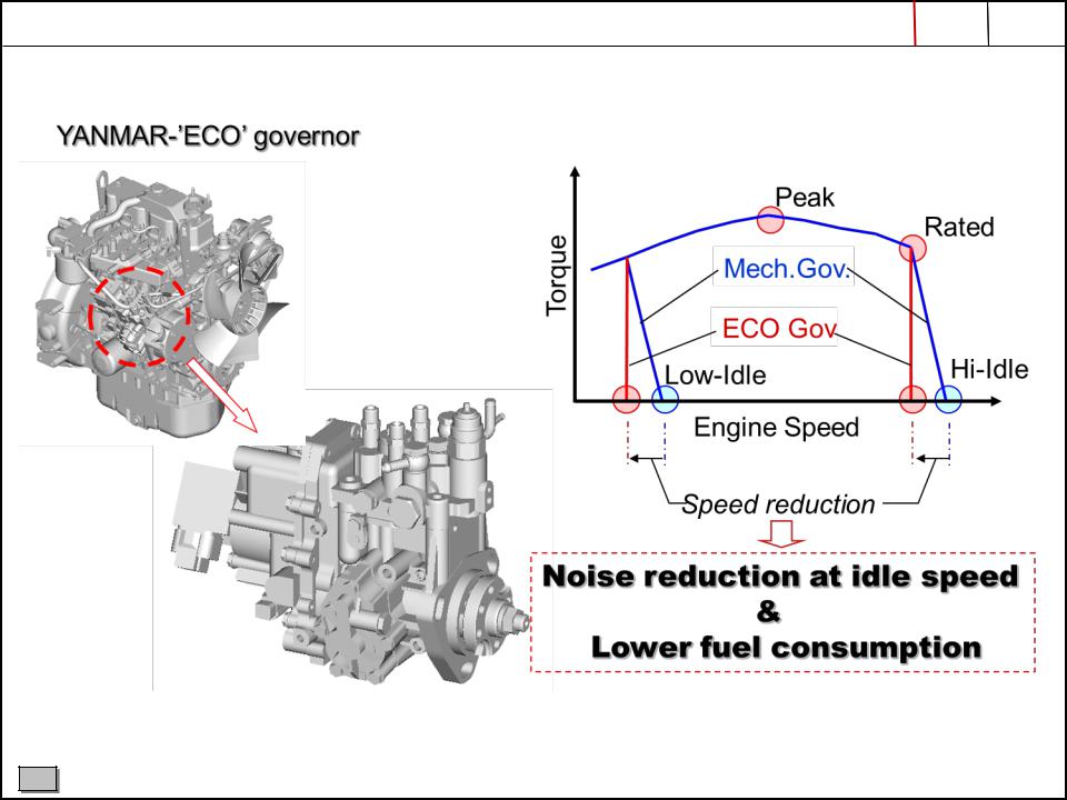
Eco-Governor is Yanmar’s unique electronics control governor system which has been used for over 10 years mainly on agricultural machines. Yanmar has renewed this system to aplly to all equipment and named it “2G Eco-Governor” which means second generation Eco-Governor. In addition an EGR valve is controlled by this system.
Idling speed control |
After heat control |
Communication function |
|
|
|
Idling speed will be adjusted |
Starting aid devices stay |
Data logging by ECO system |
depending on cooling water |
activated after start |
Connection for troubleshooting |
temperature |
|
|
|
|
|
Engine warm-up time reduced, |
|
Possible to monitor engine |
protection at high idle & less |
|
performance |
white smoke |
|
System diagnosis incl history |
|
|
|
C |
HHIE TRAINING CENTRE |
|
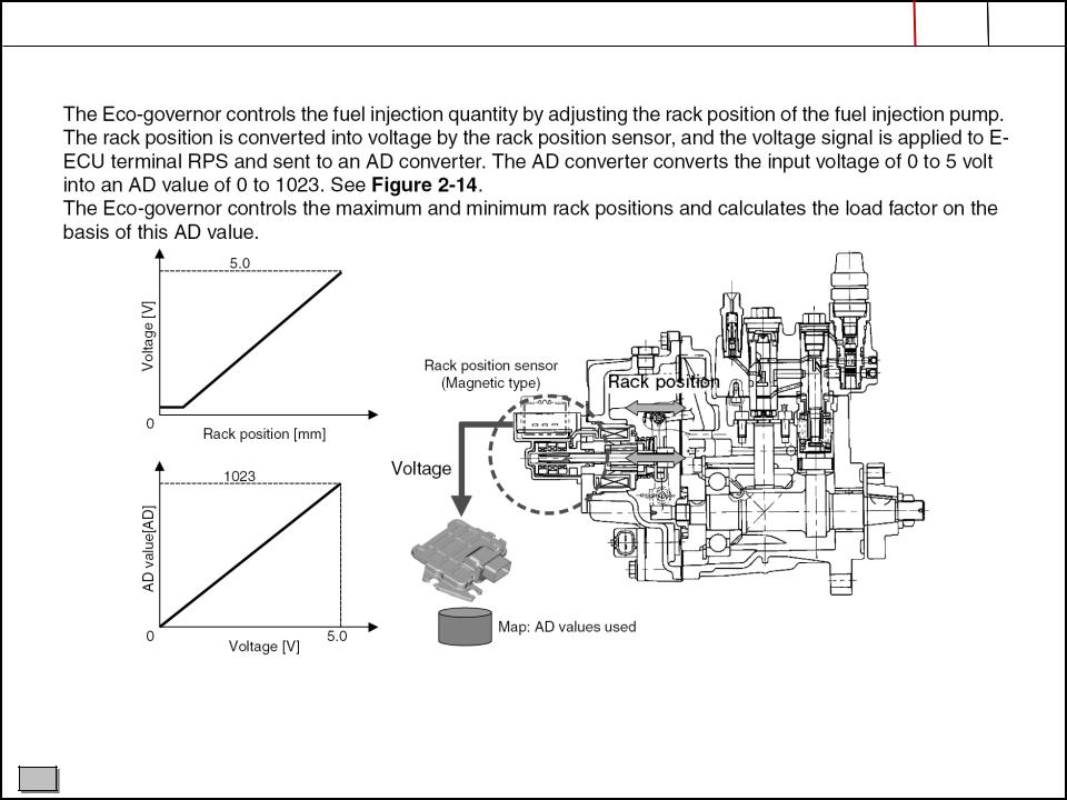
3. INJECTION PUMP - RACK CONTROL |
PAGE |
|
- 10 - |
|
|
|
|
|
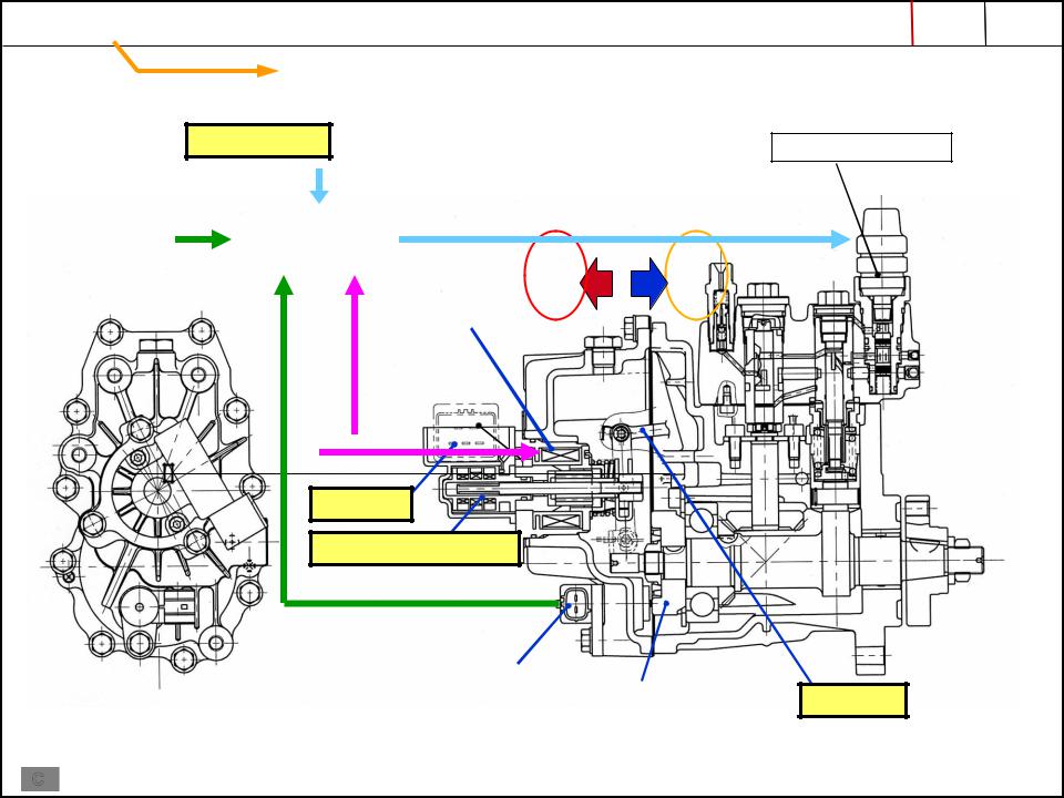
Electronically control rack by ECU |
|
|
Water Temp.
|
|
|
|
|
|
|
Actuator force |
Spring return |
|
Target |
|
|
|
|
|
||||
|
|
|
|
|
|
|
|
|
|
engine speed |
|
ECU |
|
Fuel |
Fuel |
||||
|
|
|
|
|
|
|
|||
|
|
|
|
|
|
||||
|
|
|
|
|
|
+ |
|
||
|
|
|
|
|
|
||||
|
|
|
|
|
|
Actuator |
|
|
|
|
|
|
|
|
|
|
|
|
|
|
|
|
|
|
|
|
|
|
|
|
|
|
|
|
|
|
|
|
|
|
|
|
|
|
|
|
|
|
|
Rack act.
Rack position sensor
|
|
|
Engine speed sensor |
|
|
|
|
|
|
|
|
|
|
|
|
|
|
|
|
|
|
|
Engine |
|
|
when replacing the pump, data files |
|
||
|
|
|
|
||
|
|
need to be written to the ECU>> See |
|
|
|
|
|
"TNV-ECO-diagnostic tool.pdf, p51 |
|
|
|
|
|
for more information |
|
|
|
C |
|
|
|
|
|
|
|
HHIE TRAINING CENTRE |
|||
|
|
|
|||
Solenoid valve CSD
Rack
3. INJECTION PUMP - RACK CONTROL |
PAGE |
|
- 11 - |
|
|
|
|
ECU
pin nr. 42
6 5 4 3 2 1
to ECU (pin 42) (neg. control)
to ECU
Rack |
actuator |
Rack position sensor
ECU fuse 12V


Relay |
Relay |
|
ECU Main |
||
rack actuator |
||
Power |
||
|
CR67 |
CR68 |
|
C |
HHIE TRAINING CENTRE |
|
3. INJECTION PUMP - RACK CONTROL |
PAGE |
|
- 12 - |
|
|
|
|
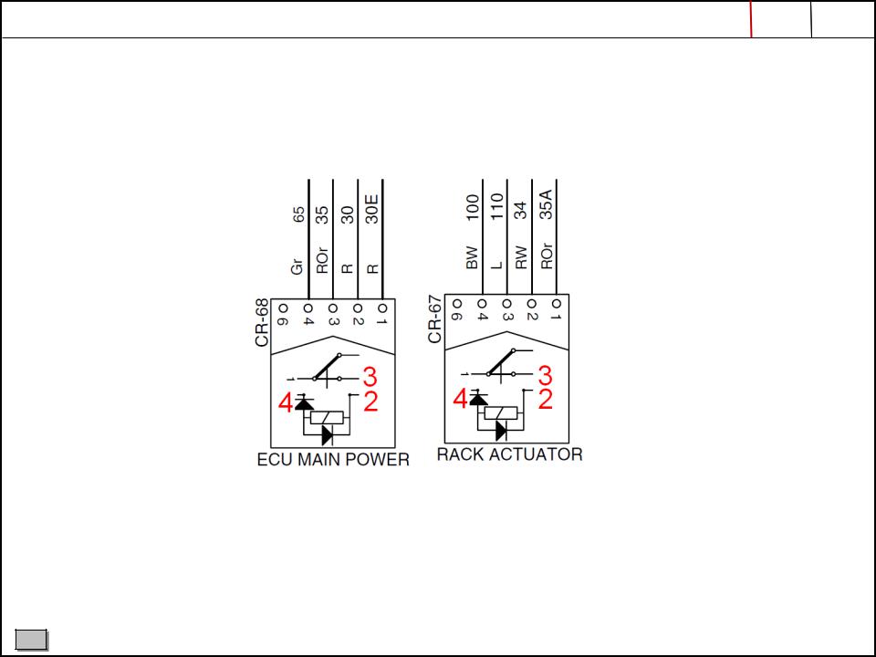
CORRECTED PIN LAY OUT FOR CR-68 (ecu main power) AND CR-67 (rack actuator) ON R80-7A
C |
HHIE TRAINING CENTRE |
|
3. INJECTION PUMP - RACK POSITION SENSOR |
PAGE |
|
|
- 13 - |
|
||
|
|
|
|
|
|
|
|
|
|
|
|
C |
HHIE TRAINING CENTRE |
|
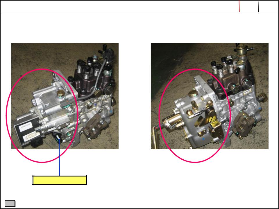
3. INJECTION PUMP - ECO 2G GOVERNOR VERSUS MECHANICAL GOVERNOR |
PAGE |
|
- 14 - |
|
|
|
|
INJ. PUMP WITH EL. GOVERNOR (on -7A & -9) |
INJ. PUMP WITH MECHANICAL GOVERNOR (on -7) |
Engine speed sensor
•magnetic type
•detects eng. speed with 12 pulsers attached to the camshaft
C |
HHIE TRAINING CENTRE |
|
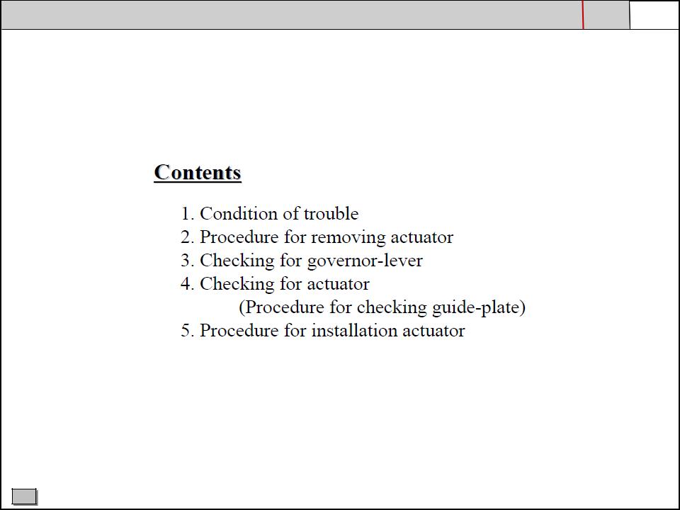
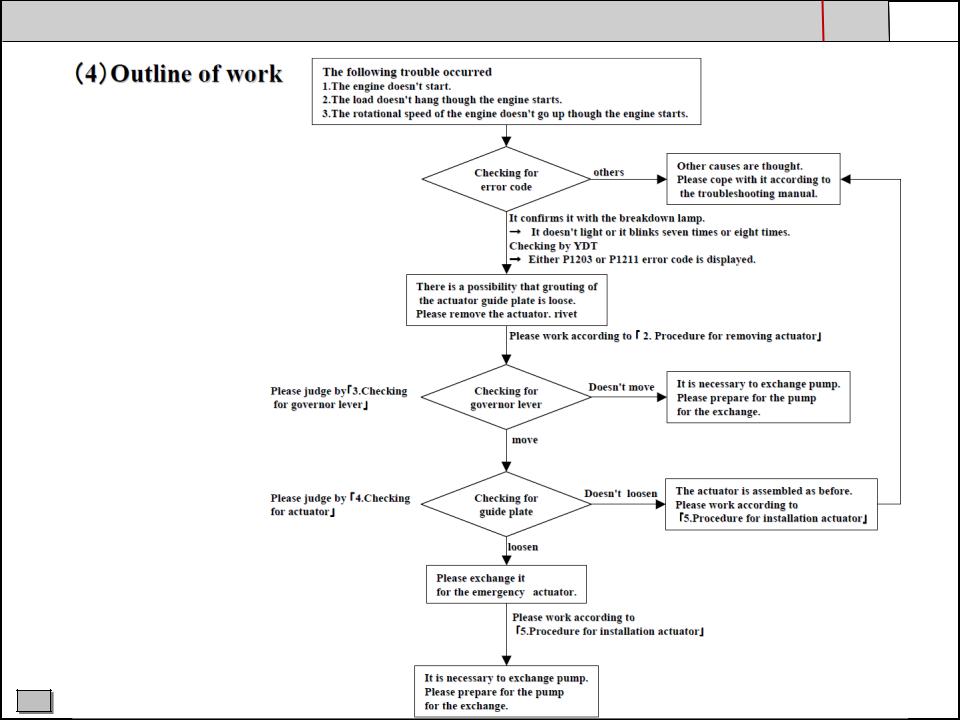
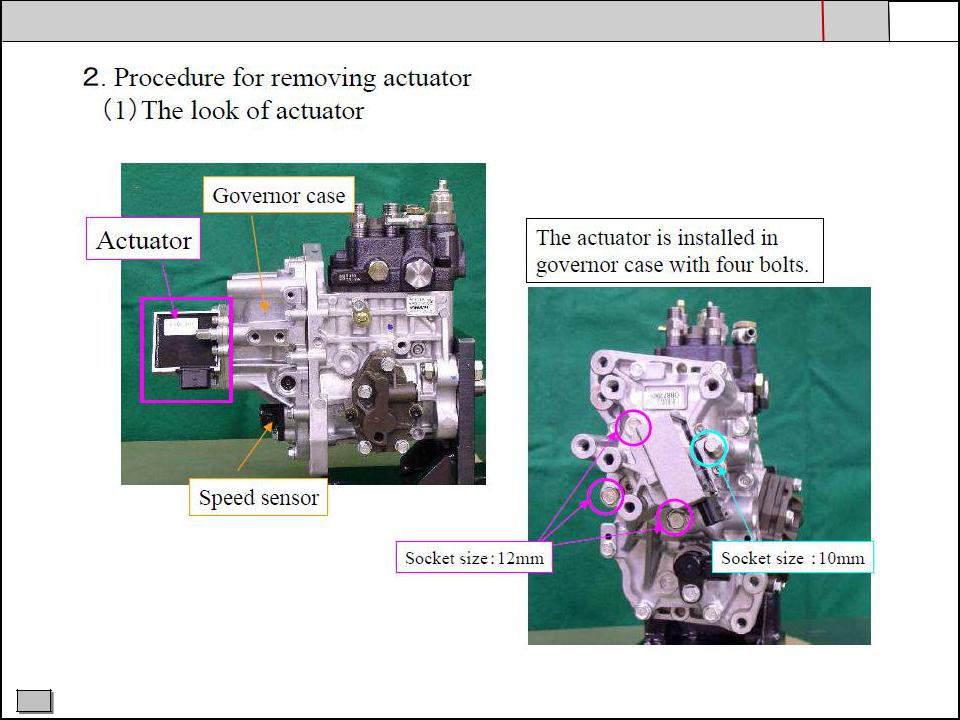
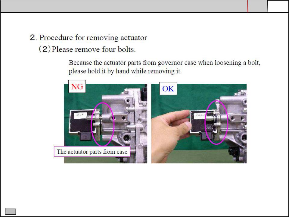
3. INJECTION PUMP - TROUBLESHOOTING FOR ACTUATOR & GOVERNOR-LEVER |
PAGE |
|
||
- 15 - |
|
|||
|
1 / 19 |
|
|
|
|
|
|
|
|
|
|
|
|
|
C |
HHIE TRAINING CENTRE |
|
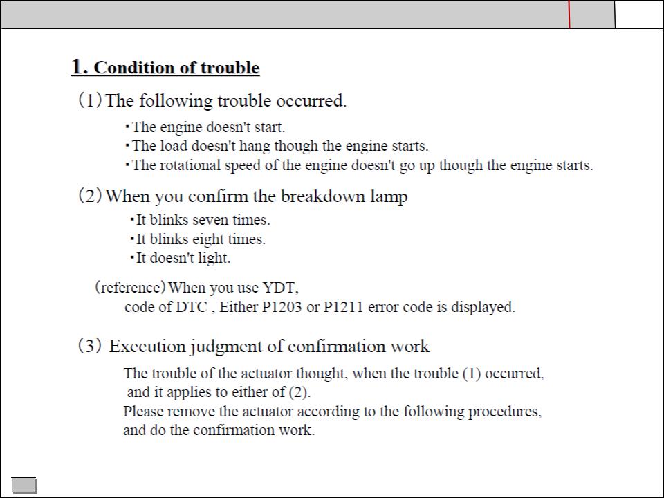
3. INJECTION PUMP - TROUBLESHOOTING FOR ACTUATOR & GOVERNOR-LEVER |
PAGE |
|
||
- 16 - |
|
|||
|
2 / 19 |
|
|
|
|
|
|
|
|
|
|
|
|
|
C |
HHIE TRAINING CENTRE |
|
3. INJECTION PUMP - TROUBLESHOOTING FOR ACTUATOR & GOVERNOR-LEVER |
PAGE |
|
||
- 17 - |
|
|||
|
3 / 19 |
|
|
|
|
|
|
|
|
|
|
|
|
|
C
3. INJECTION PUMP - TROUBLESHOOTING FOR ACTUATOR & GOVERNOR-LEVER |
PAGE |
|
||
- 18 - |
|
|||
|
4 / 19 |
|
|
|
|
|
|
|
|
|
|
|
|
|
C |
HHIE TRAINING CENTRE |
|
3. INJECTION PUMP - TROUBLESHOOTING FOR ACTUATOR & GOVERNOR-LEVER |
PAGE |
|
||
- 19 - |
|
|||
|
5 / 19 |
|
|
|
|
|
|
|
|
|
|
|
|
|
C |
HHIE TRAINING CENTRE |
|

3. INJECTION PUMP - TROUBLESHOOTING FOR ACTUATOR & GOVERNOR-LEVER |
PAGE |
|
||
- 20 - |
|
|||
|
6 / 19 |
|
|
|
|
|
|
|
|
|
|
|
|
|
C |
HHIE TRAINING CENTRE |
|
3. INJECTION PUMP - TROUBLESHOOTING FOR ACTUATOR & GOVERNOR-LEVER |
PAGE |
|
||
- 21 - |
|
|||
|
7 / 19 |
|
|
|
|
|
|
|
|
|
|
|
|
|
C |
HHIE TRAINING CENTRE |
|
 Loading...