


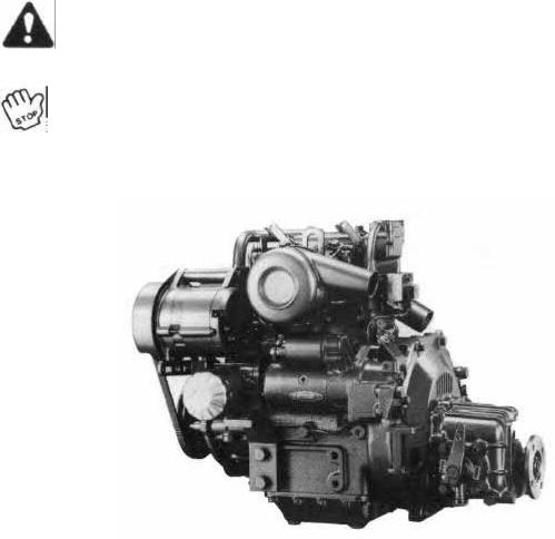
Thank you for purchasing the YANMAR Diesel Engine
This manual describes the various engine parts and prescribes simple checks for normal engine maintenance.
Before starting up your new engine, we recommend that you throughly read this manual to insure proper handling and use. If any sections are unclear or if you have any problems, please consult your nearest dealer or sales outlet.
In view of our continuing efforts to improve quality and performance, engine parts may sometimes be changed. This may result in some discrepancies in the contents of this manual.
This manual is concerned with the 2 cylinder model. Although the 1GM, 3GMD and 3HM seem to be different on the outside, their handling is the same.
Caution
This safety alert symbol indicates important safety messages in this manual. When you see this symbol, be alert to
the possibility of personal injury and carefully read the message that follows.
Important
This stop symbol indicates important proper operation messages in this manual. When you see this symbol, carefully read the message that follows.
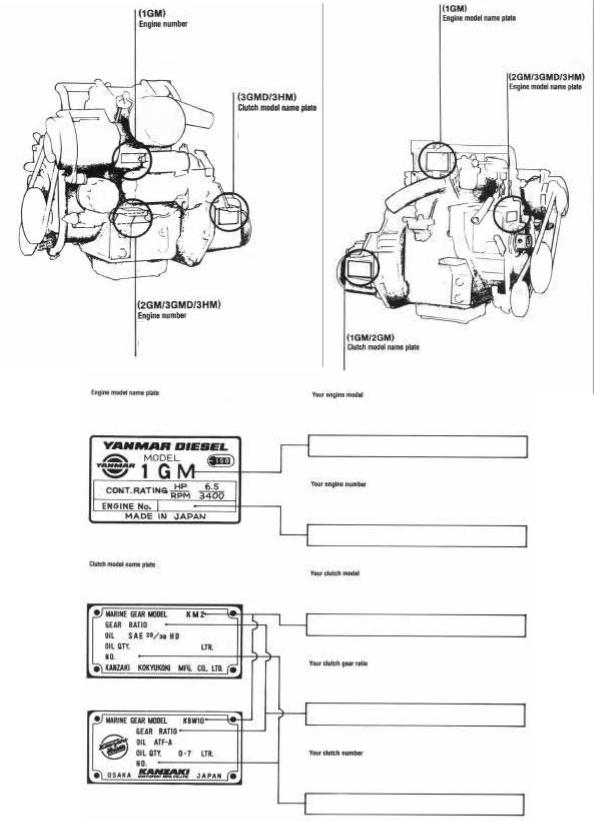
In order to deliver correct parts to you, we need accurate data on the engine you purchased. The information needed is described in the illustrations below. For ready reference, please record the information in the spaces provided under the illustrations.

I. Name of parts
1 Reduction and reversing gear
2 Output shaft coupling
3 Clutch control lever
4 Installation foot
5 Engine tube oil dipstick
6 Clutch tube oil dipstick/Supply port
7 Cooling water pump
8 Fuel feed pump
9 Exhaust manifold
10 Mixing elbow
11 Air intake silencer
12Alternator
13Lube oil filter
14Starter motor
15Decompression lever
16Anticorrosion zinc
17Fuel injection pump
18Fuel injection valve
19Crankshaft V-pulley
20Speed control lever
21Cooling water drain cock (Cylinder block/Exhaust manifold)
22Fuel filter
23Breather pipe
24Fuel injection limiter
25Engine lift plate
26Lube oil supply port
27Oil pressure sender
28Engine stop device
III. Engine installation
[3-1.1 Inspection after unpacking
During unpacking be careful not to break the engine base. Check the following points:
1)Have any nuts or bolts become loose or fallen off?
2)Have any parts become rusty?
3)Is there any water inside the engine?
4)Has any part of the engine been broken, chipped, or crushed?
5)Are any of the accessory parts/ items broken or defective?
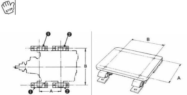
[3-2.1 Preparation of the engine foundation plate
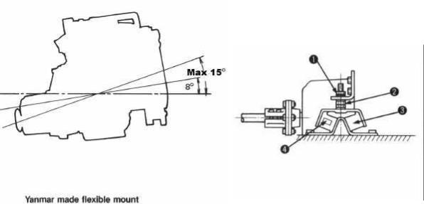
The installation angle will differ with the vessel configuration and installation location of the engine. The most suitable installation angle is 8 degrees and the maximum installation angle is 15 degrees. If it is greater than this, horsepower loss will increase and vessel speed will drop. In addition, abnormal wear of parts will occur and engine performance will be adversely affected.
[3-3.1 Engine installation
1) For the engine installation, be sure to use the flexible rubber mount.
Yanmar prepared the flexible mounts which match the respective engine characteristics as a standard accessory.
1. Lock Nut
2. Jack Nut
3. Rubber Mount
4. Indication No. (50, 70, 75, 100)
Note
Avoid splashing the flexible mount with water, oil etc.
Indication # Installation distance (unit: mm)
Engine model |
Front |
Rear |
A |
B |
|
||||
1GM |
70 |
50 |
209 |
370 |
2GM |
100 |
75 |
275 |
370 |
3GMD |
100 |
75 |
355 |
370 |
3HM |
100 |
100 |
432 |
400 |
It is convenient for installation to make the GUIDE PLATE as illustrated.
2)Be sure the propeller shaft lines up with and matches both shaft joints. If necessary adjust the height of the engine with a jack nut to line up the propeller shaft and the engine. Fit the propeller shaft and the intermediate shaft if there is one-to the engine.
With a gap gauge, measure the gap of the connection at the top, bottom, right, and left. The maximum tolerance should be less than 0.2mm. Lock nut should be as low as possible.
3)Tighten the installation bolts firmly and evenly. Do not force the bolts in if the propeller shaft does not line up.
Important
After 50 hours operation, check that the propeller shaft lines up again, and readjust if necessary.
View From Top
1 - Rear 2 - Front
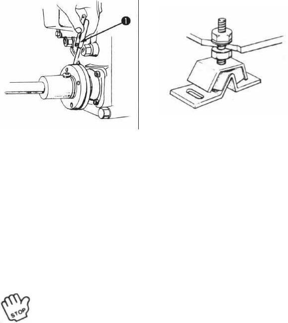
1. Gap gauges
[3-4.1 Propeller, propeller shaft
1)Select a propeller which is suitable for the size and shape of the vessel, as well as for its intended usage. An extremely small or large propeller will reduce the speed of the vessel and overload the engine, which may lead to engine break down. It is recommended that a propeller be selected in consultation with a reputable dealer. However, the best way to make sure the propeller fits the vessel is to conduct a test run after installation.
2)It is effective to use a proper flexible stern tube to reduce vibration.
[3-5.1 Cooling water supply device
1) The engine should be operated only after checking the cooling water piping is completed.
Important
If the Cooling water pump is operated without water, the rubber impeller inside the pump will be broken.
2) Kingston cock installation. Install the canvas on the outside of the hull, and the canvas or rubber packing on the inside of the hull; tighten the kingston cock. Installation directions are given in the figure at the right. Install the kingston cock cover as shown.
3) Piping
For the cooling water pipe, use a rubber hose with an inside diameter of 13mm. Piping should be kept as straight and short as possible. If the pipe is too long, it will be difficult to draw water up.
4) Connect the rubber hoses to the kingston cock, cooling water pump inlet, and engine cooling water outlet, and secure with hose clamps.
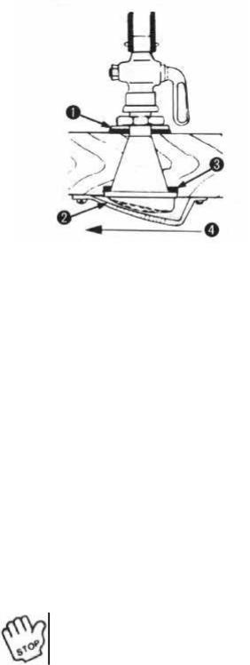
Piping Diagram
1. Inside Packing
2. Kingston cock cover
3. Outside Packing
4. Direction of vessel movement
5) Seawater strainer
The seawater pump will be damaged if foreign matter is allowed to get into it. Therefore, attach a seawater strainer between the seawater pump inlet and the seawater cock when the sea water cock is not already equipped with a strainer.
6) Exhaust pipe layout
Be sure to use the water-lock. Installation of piping should be done as shown in the following diagram.
6-a)
In case the water outlet of the engine side (A) is above water line.
6-b)
In case the water outlet of the engine side (A) is below water line.
7) Air ventilation and Intake pipe
If the engine is operated at below normal output, incomplete combustion can occur as a result of an overheated engine room. Therefore, the engine room should be adequately ventilated.
Important
During piping works be sure to cover the intake opening to prevent the entry of foreign matter.
1.Seawater pump
2.Seawater strainer
3.Kingston cock
1. W.L.
2. Waterlock
3. Above seawater line
1. W.L.
2. Waterlock
3. Vacuum valve
I3-6.] Remote control
1) Control cable Use only the single lever remote control device with 1GM 2GM, 3GM and 3HM engines.
Note
The dual lever remote control device cannot be used.
Recommended |
Control Cable |
Cable Clamp |
Connecting metal |
Cable |
|
|
fittings |
|
|
|
|
Speed Control |
Morse 33-C |
Yanmar Standard |
Yanmar Standard |
|
|
|
|
Clutch Control |
Morse 33-C |
Yanmar Standard |
Yanmar Standard |
|
|
|
|
Engine Stop (option) |
Yanmar made |
|
|
|
Morse |
|
|
|
|
|
|
2) Speed control |
|
|
|
2-a) A spring is attached to the connector to absorb shock when operating the speed control lever. Make the wiring so that the spring works when the throttle is "idling" as illustrated.
1. Spring
2. Speed Control Lever
3. Connector
4. Idle adjusting bolt
Note
1)Fix the wire to the cable clamp of the F.O. filter side.
2)Cable connector has M5 thread.
2-b)
After completing of wiring, check the following points:
2-b)-1.
That the remote control lever and speed control lever can be moved smoothly through the whole stroke.
2-b)-2
That the idle speed adjuster regulates the speed to 850-900 rpm, after all preparations for starting the engine have been completed.
1.Cable clamp
3)Clutch Control
3-a)
Cone Clutch (for 1GM, 2GM, 3GMD)
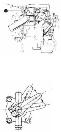
3-a)-1.
Remove the spring joint from the operation lever.
3-a)-2.
With the spring joint disconnected from the operation lever, move the operation lever forward and reverse, to make sure that the strokes from the neutral position are the same.
3-a)-3.
Attach the spring joint to the operation lever 60mm from the shaft lever center.
The stroke from the neutral position moves through a distance of 24.4 to 35.Ohm. When the spring joint is attached to the hole 52mm from the center of the shift lever, these strokes must be 21.1-30.Ohm.
Note
The operation lever may not move smoothly when there is no lubrication oil in the clutch case.
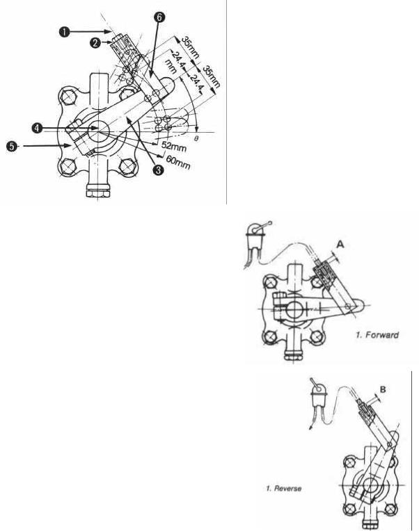
1. Remote Control Cable
2. M5 Thread
3. Operation Lever
4. Shaft
5. Clutch Case side cover
6. Spring joint
3-a)-4
Move the remote control lever to the forward position, and make sure that the M5 thread of the spring joint reaches to the inside of the joint.
In this position, the output shaft (propeller shaft) of the clutch should rotate clockwise as viewed from the stern.
3-a)-5.
Move the remote control lever to the reverse position, and make sure that the M5 thread of the spring joint reaches the outside of the joint. In this position, the output shaft (propeller shaft) of the clutch should rotate counter-clockwise as viewed from the stern.
3-a)-6.
Adjust the M5 thread depth so that the value of A, and 16 are nearly the same.
3-a)-7.
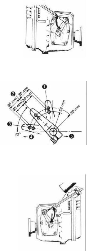
Make sure that the angle made between the spring joint and the clutch control lever forms 90 degrees.
3-b)
Kanzaki-Hurth clutch (for 3GMD and 3HM) To connect the cable, the operating cable must be positioned at right angles to the shift lever when the shift lever is in the neutral position. The shift play, measured at the pivot point of the shift lever, must be at least 35mm to each side (reverse and forward) from the neutral position. A greater shift play has no adverse effect on the marine gearbox. After connecting the linkage, confirm that the remote control and the shift lever on the marine gearbox work properly. A typical linkage arrangement is illustrated in the figure below.
1. Astern
2. Neutral
3. Ahead
Note
Since the cable stroke may be insufficient, two holes are drilled in the shift lever.
When the cable is attached to the hole 60mm from the center of the rotation of the shift lever, the strokes from the center to the forward and reverse sides must be 35mm. When the cable is attached to the hole 52mm from the rotation of the shift lever, these strokes must be 30mm.
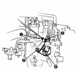
4) Engine stop remote control Connect the engine stop remote control cable as in the illustration, after completing the wiring check that the engine stop lever can be moved smoothly through the whole stroke.
4.Propeller side
5.Engine Side
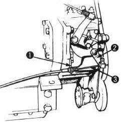
1. Clamp
2. Engine Stop lever
3. Engine stop remote control cable
[3-7.] Recommended battery capacity
Use sufficient capacity of battery.
1GM, 2GM, 3GMD |
- |
12V |
- 70AH (Mini) |
3HM |
- |
12V |
- 100AH (Mini) |
IV. After launching
1)Check for water or air intake around the gland part of the stern tube and the kingston cock fitting.
2)Make sure that the engine installation bolts and shaft joints are firmly secured.
3)Release compression with the decompression lever and slowly run the engine with the engine starting handle. Relative compression can be determined by comparing the weight (resistance when turning) of the clutch handle when placed in the neutral, ahead, and astern positions. When there is little weight difference among the three positions, decompression is complete. If the clutch is heavier when engaged than when disengaged, this indicates that the shaft is not in the correct position. If the engine is operated under this condition, a broken propeller shaft may result. Check the alignment of the propeller shaft and the engine.
 Loading...