


 Loading...
YZF-R6T YZF-R6TC
SUPPLEMENTARY SERVICE MANUAL
LIT-11616-18-45 |
5SL-28197-12 |

FOREWORD
This Supplementary Service Manual has been prepared to introduce new service and data for the YZF-R6T/YZF-R6TC. For complete service information procedures it is necessary to use this Supplementary Service Manual together with the following manual.
YZF-R6R/YZF-R6SR/YZF-R6RC/YZF-R6SRC SERVICE MANUAL:
LIT-11616-16-45 (5SL-28197-10)
YZF-R6S/YZF-R6SC SUPPLEMENTARY SERVICE MANUAL: LIT-11616-17-46 (5SL-28197-11)
EAS00001
YZF-R6T/YZF-R6TC
SUPPLEMENTARY
SERVICE MANUAL ©2004 by Yamaha Motor Corporation, U.S.A.
First edition, September 2004
All rights reserved. Any reproduction or unauthorized use without the written permission of Yamaha Motor Corporation, U.S.A. is expressly prohibited.
Printed in U.S.A.
P/N LIT-11616-18-45

EAS00030
NOTICE
This manual was produced by the Yamaha Motor Company, Ltd. primarily for use by Yamaha dealers and their qualified mechanics. It is not possible to include all the knowledge of a mechanic in one manual. Therefore, anyone who uses this book to perform maintenance and repairs on Yamaha vehicles should have a basic understanding of mechanics and the techniques to repair these types of vehicles. Repair and maintenance work attempted by anyone without this knowledge is likely to render the vehicle unsafe and unfit for use.
This model has been designed and manufactured to perform within certain specifications in regard to performance and emissions. Proper service with the correct tools is necessary to ensure that the vehicle will operate as designed. If there is any question about a service procedure, it is imperative that you contact a Yamaha dealer for any service information changes that apply to this model. This policy is intended to provide the customer with the most satisfaction from his vehicle and to conform to federal environmental quality objectives.
Yamaha Motor Company, Ltd. is continually striving to improve all of its models. Modifications and significant changes in specifications or procedures will be forwarded to all authorized Yamaha dealers and will appear in future editions of this manual where applicable.
NOTE:
•This Service Manual contains information regarding periodic maintenance to the emission control system. Please read this material carefully.
•Designs and specifications are subject to change without notice.
EAS00040
IMPORTANT MANUAL INFORMATION
Particularly important information is distinguished in this manual by the following.
WARNING
CAUTION:
The Safety Alert Symbol means ATTENTION! BECOME ALERT! YOUR SAFETY IS INVOLVED!
Failure to follow WARNING instructions could result in severe injury or death to the motorcycle operator, a bystander or a person checking or repairing the motorcycle.
A CAUTION indicates special precautions that must be taken to avoid damage to the motorcycle.
NOTE: |
A NOTE provides key information to make procedures easier or clearer. |

EAS00007
HOW TO USE THIS MANUAL
This manual is intended as a handy, easy-to-read reference book for the mechanic. Comprehensive explanations of all installation, removal, disassembly, assembly, repair and check procedures are laid out with the individual steps in sequential order.
 The manual is divided into chapters. An abbreviation and symbol in the upper right corner of each page indicate the current chapter.
Refer to “SYMBOLS”.
 Each chapter is divided into sections. The current section title is shown at the top of each page, except in Chapter 3 (“PERIODIC CHECKS AND ADJUSTMENTS”), where the sub-section title(s) appears.
 Sub-section titles appear in smaller print than the section title.
 To help identify parts and clarify procedure steps, there are exploded diagrams at the start of each removal and disassembly section.
 Numbers are given in the order of the jobs in the exploded diagram. A circled number indicates a disassembly step.
 Symbols indicate parts to be lubricated or replaced.
Refer to “SYMBOLS”.
 A job instruction chart accompanies the exploded diagram, providing the order of jobs, names of parts, notes in jobs, etc.
 Jobs requiring more information (such as special tools and technical data) are described sequentially.

EAS00008
SYMBOLS
The following symbols are not relevant to every vehicle.
Symbols  to
to  indicate the subject of each chapter.
 General information
 Specifications
 Periodic checks and adjustments
 Chassis
 Engine
 Cooling system
 Fuel injection system
 Electrical system
  Troubleshooting
Symbols  to
to  indicate the following.
 Serviceable with engine mounted
 Filling fluid
 Lubricant
 Special tool
 Tightening torque
 Wear limit, clearance
 Engine speed
  Electrical data
Symbols  to
to  in the exploded diagrams indicate the types of lubricants and lubrication points.
 Engine oil
 Gear oil
 Molybdenum-disulfide oil
 Wheel-bearing grease
 Lithium-soap-based grease
 Molybdenum-disulfide grease
Symbols  to
to  in the exploded diagrams indicate the following.
 Apply locking agent (LOCTITE®)
  Replace the part

CONTENTS
GENERAL INFORMATION
SPECIAL TOOLS. . . . . . . . . . . . . . . . . . . . . . . . . . . . . . . . . . . . . . . . . 1
SPECIFICATIONS
GENERAL SPECIFICATIONS . . . . . . . . . . . . . . . . . . . . . . . . . . . . . . . 2 ENGINE SPECIFICATIONS. . . . . . . . . . . . . . . . . . . . . . . . . . . . . . . . . 2 CHASSIS SPECIFICATIONS. . . . . . . . . . . . . . . . . . . . . . . . . . . . . . . . 3 ELECTRICAL SPECIFICATIONS . . . . . . . . . . . . . . . . . . . . . . . . . . . . 4 TIGHTENING TORQUES. . . . . . . . . . . . . . . . . . . . . . . . . . . . . . . . . . . 5
ENGINE TIGHTENING TORQUES . . . . . . . . . . . . . . . . . . . . . . . . 5 CHASSIS TIGHTENING TORQUES . . . . . . . . . . . . . . . . . . . . . . . 5 CABLE ROUTING . . . . . . . . . . . . . . . . . . . . . . . . . . . . . . . . . . . . . . . . 6
PERIODIC CHECKS AND ADJUSTMENTS
BLEEDING THE HYDRAULIC BRAKE SYSTEM . . . . . . . . . . . . . . 20 ADJUSTING THE FRONT FORK LEGS. . . . . . . . . . . . . . . . . . . . . 22
CHASSIS
FRONT WHEEL AND BRAKE DISCS. . . . . . . . . . . . . . . . . . . . . . . . . 24 FRONT AND REAR BRAKES . . . . . . . . . . . . . . . . . . . . . . . . . . . . . . . 25 FRONT BRAKE PADS . . . . . . . . . . . . . . . . . . . . . . . . . . . . . . . . . . 25 FRONT BRAKE MASTER CYLINDER . . . . . . . . . . . . . . . . . . . . . . 26 FRONT BRAKE CALIPERS . . . . . . . . . . . . . . . . . . . . . . . . . . . . . . 29
ASSEMBLING AND INSTALLING THE FRONT BRAKE MASTER CYLINDER . . . . . . . . . . . . . . . . . . . . . . . . . . . . . . . . . . . . . . . . . . . 31
FRONT FORK . . . . . . . . . . . . . . . . . . . . . . . . . . . . . . . . . . . . . . . . . . . 33 FRONT FORK LEGS . . . . . . . . . . . . . . . . . . . . . . . . . . . . . . . . . . . 33 DISASSEMBLING THE FRONT FORK LEGS . . . . . . . . . . . . . . . . 36 CHECKING THE FRONT FORK LEGS . . . . . . . . . . . . . . . . . . . . . 37 ASSEMBLING THE FRONT FORK LEGS . . . . . . . . . . . . . . . . . . . 38
SWINGARM AND DRIVE CHAIN . . . . . . . . . . . . . . . . . . . . . . . . . . . . 43 CHECKING THE DRIVE CHAIN. . . . . . . . . . . . . . . . . . . . . . . . . . . 43
COOLING SYSTEM
RADIATOR. . . . . . . . . . . . . . . . . . . . . . . . . . . . . . . . . . . . . . . . . . . . . . 45

ELECTRICAL SYSTEM
ELECTRIC STARTING SYSTEM. . . . . . . . . . . . . . . . . . . . . . . . . . . . . 47 CIRCUIT DIAGRAM . . . . . . . . . . . . . . . . . . . . . . . . . . . . . . . . . . . . 47 TROUBLESHOOTING . . . . . . . . . . . . . . . . . . . . . . . . . . . . . . . . . . 48 COOLING SYSTEM . . . . . . . . . . . . . . . . . . . . . . . . . . . . . . . . . . . . . . . 51 CIRCUIT DIAGRAM . . . . . . . . . . . . . . . . . . . . . . . . . . . . . . . . . . . . 51 TROUBLESHOOTING . . . . . . . . . . . . . . . . . . . . . . . . . . . . . . . . . . 52
YZF-R6T/YZF-R6TC WIRING DIAGRAM
SPECIAL TOOLS
EAS00027
GEN INFO
GENERAL INFORMATION
SPECIAL TOOLS
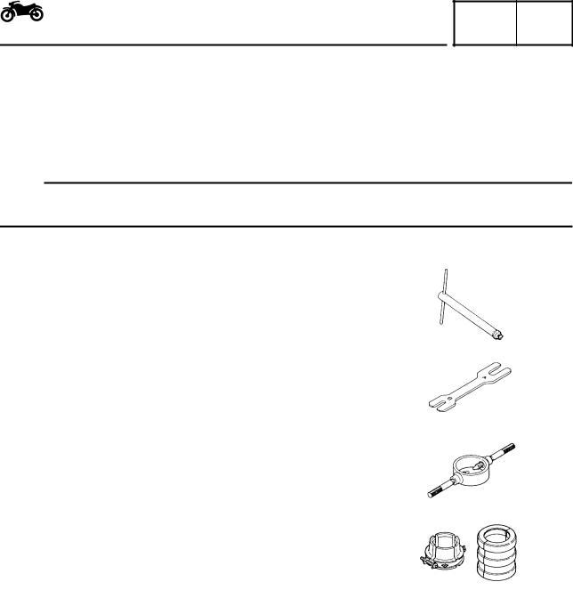
The following special tools are necessary for complete and accurate tune-up and assembly. Use only the appropriate special tools as this will help prevent damage caused by the use of inappropriate tools or improvised techniques. Special tools, part numbers or both may differ depending on the country. When placing an order, refer to the list provided below to avoid any mistakes.
NOTE:
•For U.S.A. and Canada, use part number starting with “YM-”, “YU-”, or “ACC-”.
•For others, use part number starting with “90890-”.
Tool No. |
Tool name/Function |
Illustration |
|
|
|
|
Damper rod holder |
|
90890-01423 |
This tool is used to hold the damper rod |
|
YM-01423 |
|
|
assembly when loosening or tightening the |
|
|
|
|
|
|
damper rod assembly bolt. |
|
|
|
|
|
Rod holder |
|
90890-01434 |
|
|
YM-01434 |
This tool is used to support the damper |
|
|
|
|
|
adjusting rod. |
|
|
|
|
|
Fork spring compressor |
|
90890-01441 |
|
|
YM-01441 |
This tool is used to disassemble or assemble |
|
|
|
|
|
the front fork legs. |
|
|
|
|
|
Fork seal driver |
|
90890-01442 |
|
|
YM-01442 |
This tool is used to install the front fork’s oil |
|
|
|
|
|
seal and dust seal. |
|
|
|
|
1

GENERAL SPECIFICATIONS/ENGINE SPECIFICATIONS |
|
SPEC |
|
|
|
|
|
|
|
|
|
SPECIFICATIONS |
|
|
|
GENERAL SPECIFICATIONS |
|
|
|
Item |
Standard |
Limit |
|
|
|
Model code |
5SLR (USA except for CAL) |
••• |
|
5SLS (CAL) |
|
Dimensions |
|
|
Overall length |
2,045 mm (80.5 in) |
••• |
Overall width |
690 mm (27.2 in) |
••• |
Overall height |
1,105 mm (43.5 in) |
••• |
Seat height |
830 mm (32.7 in) |
••• |
Wheelbase |
1,385 mm (54.5 in) |
••• |
Minimum ground clearance |
145 mm (5.7 in) |
••• |
Minimum turning radius |
3,800 mm (149.6 in) |
••• |
|
|
|
Weight |
|
|
Wet (with oil and a full fuel tank) |
183 kg (404 lb) (USA except for CAL) |
••• |
|
184 kg (406 lb) (CAL) |
••• |
Maximum load (except motorcycle) |
192 kg (423 lb) (USA except for CAL) |
••• |
|
191 kg (421 lb) (CAL) |
••• |
|
|
|
ENGINE SPECIFICATIONS
Item |
Standard |
Limit |
|
|
|
Throttle bodies |
|
|
Model (manufacturer) × quantity |
40EIS (MIKUNI) × 4 |
••• |
ID mark |
5SLM 30 (5SLR), 5SLS 40 (5SLS) |
••• |
|
|
|
2

CHASSIS SPECIFICATIONS |
|
SPEC |
|
|
|
|
|
|
|
|
|
CHASSIS SPECIFICATIONS |
|
|
|
Item |
Standard |
Limit |
|
|
|
Frame |
|
|
Caster angle |
24.5° |
••• |
Trail |
95 mm (3.74 in) |
••• |
|
|
|
Front tire |
|
|
Size |
120/70 ZR17 M/C (55W) |
••• |
Model (manufacturer) |
Pilot POWER C (MICHELIN) |
••• |
|
D218FM (DUNLOP) |
|
|
|
|
Rear tire |
|
|
Model (manufacturer) |
Pilot POWER (MICHELIN) |
••• |
|
D218M (DUNLOP) |
|
Tire pressure (cold) |
290 kPa (2.9 kgf/cm2, 2.9 bar, 41.3 psi) |
|
0 ~ 90 kg (0 ~ 198 lb) |
••• |
|
90 ~ 192 kg (198 ~ 426 lb) |
290 kPa (2.9 kgf/cm2, 2.9 bar, 41.3 psi) |
••• |
(USA except for CAL) |
290 kPa (2.9 kgf/cm2, 2.9 bar, 41.3 psi) |
|
90 ~ 191 kg (198 ~ 423 lb) (CAL) |
••• |
|
High-speed riding |
290 kPa (2.9 kgf/cm2, 2.9 bar, 41.3 psi) |
••• |
Front brakes |
|
|
Brake lever free play |
6.7 ~ 18.1 mm (0.26 ~ 0.71 in) |
••• |
Brake discs |
|
|
Diameter × thickness |
310 × 4.5 mm (12.20 × 0.18 in) |
••• |
Min. thickness |
••• |
4.0 mm |
|
|
(0.16 in) |
Master cylinder inside diameter |
16 mm (0.63 in) |
••• |
|
|
|
Rear brake |
|
|
Brake pedal freeplay |
4.3 ~ 9.0 mm (0.17 ~ 0.35 in) |
••• |
|
|
|
3
CHASSIS SPECIFICATIONS/ |
|
SPEC |
|
ELECTRICAL SPECIFICATIONS |
|
|
|
|
|
|
|
|
|
|
|
Item |
Standard |
Limit |
|
|
|
Front suspension |
|
|
Spring |
|
|
Free length |
248.8 mm (9.80 in) |
243.8 mm |
|
|
(9.60 in) |
Installed length |
244.3 mm (9.62 in) |
••• |
Spring rate (K1) |
8.8 N/mm (0.90 kg/mm, 50.22 lb/in) |
••• |
Spring stroke (K1) |
0 ~ 120 mm (0 ~ 4.7244 in) |
••• |
Inner tube outer diameter |
41 mm (1.61 in) |
••• |
Fork oil |
|
|
Quantity (each front fork leg) |
0.475 L (0.418 lmp qt, 0.502 US qt) |
••• |
Level (from the top of the outer tube, |
92 mm (3.62 in) |
••• |
with the outer tube fully compressed, |
|
|
and without the fork spring) |
|
|
Spring preload adjusting positions |
|
|
Minimum |
8 |
••• |
Standard |
7 |
••• |
Maximum |
0 |
••• |
Rebound damping adjusting positions |
|
|
Minimum* |
10 |
••• |
Standard* |
6 |
••• |
Maximum* |
1 |
••• |
Compression damping adjusting |
|
|
positions |
|
|
Minimum* |
13 |
••• |
Standard* |
6 |
••• |
Maximum* |
1 |
••• |
*from the fully turned-in position |
|
|
|
|
|
Rear suspension |
|
|
Spring |
|
|
Free length |
167.5 mm (6.59 in) |
••• |
Installed length |
157.5 mm (6.2 in) |
••• |
Spring rate (K1) |
103 N/mm (10.5 kg/mm, 587.83 lb/in) |
••• |
|
|
|
Drive chain |
|
|
Maximum 15-link section |
••• |
239.3 mm |
|
|
(9.42 in) |
|
|
|
ELECTRICAL SPECIFICATIONS
Item |
Standard |
Limit |
|
|
|
Ignition system |
|
|
CDI unit model (manufacturer) |
F8T828 (MITSUBISHI) |
••• |
Fuses (amperage × quantity) |
15 A × 2 |
|
Radiator fan motor fuse |
••• |
|
|
|
|
4
|
TIGHTENING TORQUES |
|
SPEC |
|
||||||||||||||
|
|
|
|
|
|
|||||||||||||
|
|
|
|
|
|
|
|
|
|
|
|
|
|
|
|
|
|
|
TIGHTENING TORQUES |
|
|
|
|
|
|
|
|
|
|
|
|
|
|
|
|
|
|
ENGINE TIGHTENING TORQUES |
|
|
|
|
|
|
|
|
|
|
|
|
|
|
|
|
|
|
|
|
|
|
|
|
|
|
|
|
|
|
|
|
|
|
|||
Item |
Fastener |
Thread |
|
Q’ty |
|
Tightening torque |
Remarks |
|||||||||||
|
|
|
|
|
|
|
|
|
|
|
||||||||
|
size |
|
|
Nm |
|
m•kg |
|
ft•lb |
||||||||||
|
|
|
|
|
|
|
|
|
|
|
||||||||
|
|
|
|
|
|
|
|
|
|
|
|
|
|
|
|
|
|
|
Clutch boss |
Nut |
|
M20 |
|
1 |
|
90 |
|
9.0 |
|
|
65 |
Use a lock |
|||||
|
|
|
|
|
|
|
|
|
|
|
|
|
|
|
|
|
washer |
|
Cylinder identification sensor |
Bolt |
|
M6 |
|
1 |
|
7.5 |
|
0.75 |
|
5.4 |
Yamaha bond No.1215 |
||||||
|
|
|
|
|
|
|
|
|
|
|
|
|
|
|
|
|
|
|
CHASSIS TIGHTENING TORQUES |
|
|
|
|
|
|
|
|
|
|
|
|
|
|
|
|
|
|
|
|
|
|
|
|
|
|
|
|
|
|
|||||||
Item |
|
|
Thread |
|
Tightening torque |
|
|
Remarks |
||||||||||
|
|
size |
|
Nm |
|
m•kg |
ft•lb |
|
|
|||||||||
|
|
|
|
|
|
|
|
|
||||||||||
|
|
|
|
|
|
|
|
|
|
|
|
|
|
|||||
Handlebar and front fork |
|
|
M8 |
|
32 |
|
3.2 |
|
2.3 |
|
|
|
|
|||||
Front fender and front fork |
|
|
M6 |
|
6 |
|
|
0.6 |
|
4.3 |
|
|
|
|
||||
Rear brake master cylinder and footrest bracket |
|
M8 |
|
13 |
|
1.3 |
|
9.4 |
|
|
|
|
||||||
Front brake caliper and front fork |
|
|
M10 |
|
35 |
|
3.5 |
|
25 |
|
|
|
|
|
||||
Front master cylinder bleed screw |
|
|
M8 |
|
6 |
|
|
0.6 |
|
4.3 |
|
|
|
|
||||
Brake caliper bleed screw |
|
|
M8 |
|
5 |
|
|
0.5 |
|
3.6 |
|
|
|
|
||||
Front wheel axle pinch bolt |
|
|
M8 |
|
21 |
|
2.1 |
|
15 |
|
|
See NOTE |
||||||
|
|
|
|
|
|
|
|
|
|
|
|
|
|
|
|
|
|
|
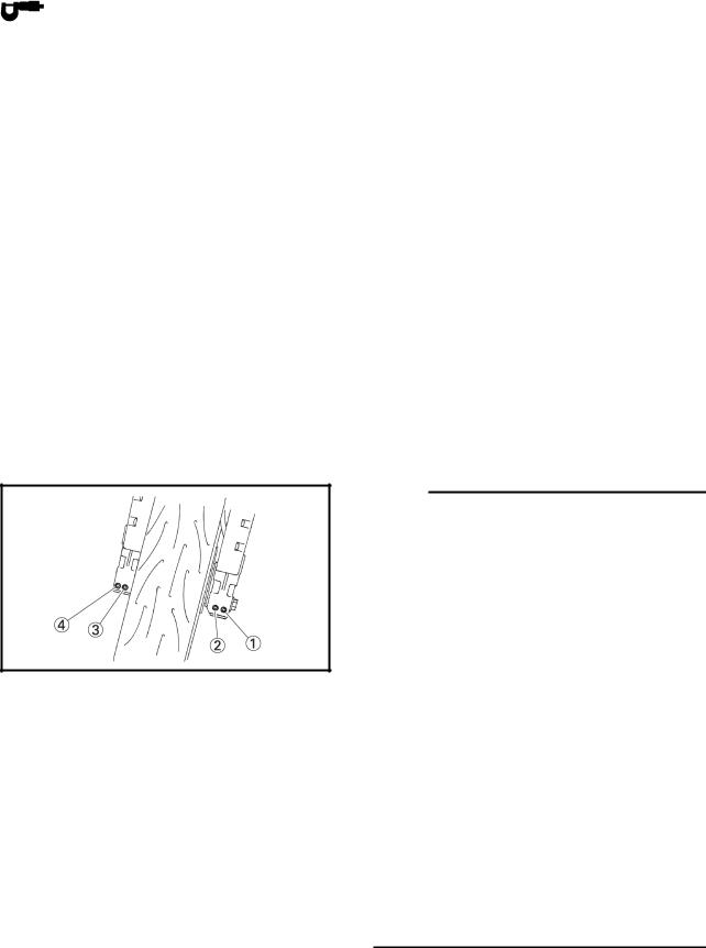
NOTE:
1. Insert the front wheel axle from the right side and tighten it with the flange bolt from the left side to 91 Nm (9.1 m•kg, 66 ft•lb).
2. In the order from the pinch bolt  → pinch bolt
  → pinch bolt
  , tighten each bolt to 21 Nm (2.1 m•kg, 15 ft•lb) without performing temporary tightening.
3. Check that the end face of the axle head and the end face of the fork side are flushmounted. If they are out of alignment, make sure to fit them by adding the external force by hand or with a plastic hammer, etc.
If the end face of the axle is not parallel to the end face of the fork, align them so that one point of the axle circumference is positioned on the end face of the fork.
At this stage, it can be accepted if the end face of the axle becomes partially concave to the end face of the fork.
4. In the order from the pinch bolt  → pinch bolt
  → pinch bolt
  , tighten each bolt to 21 Nm (2.1 m•kg, 15 ft•lb) without performing temporary tightening.
5

|
CABLE ROUTING |
|
SPEC |
|
|
|
|
|
|
|
|
|
|
|
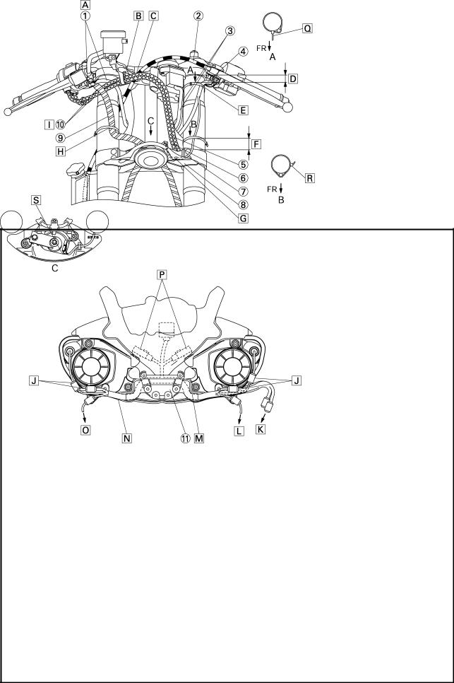
CABLE ROUTING |
Pass the right handlebar switch lead inside the |
|||
Right handlebar switch lead |
||||
Clutch cable |
front brake hoses and over the throttle cables. |
|||
Main switch lead |
Install the throttle cables to the hook so that the |
|||
Left handlebar switch lead |
pulling side of the throttle cables is routed down- |
|||
Throttle cable (return side) |
ward. |
|
|
|
Throttle cable (pull side) |
Pass the clutch cable through the guide. |
|||
Horn lead |
Plastic locking tie shall be positioned at 15 mm |
|||
Steering cover |
(0.59 in) below from the upper bracket. |
|||
Front brake hose |
Clamp the left handlebar switch lead to the front fork |
|||
Throttle cables |
with the plastic locking tie and cut the tip of the tie. |
|||
Joint |
Clamp it to the protector section. |
|||
|
Clamping position should be 10 mm (0.39 in) or |
|||
|
lower from the top end of the under bracket. |
|||
 Attach the horn lead to the hook on the steering cover.
6
CABLE ROUTING |
|
SPEC |
|
|
|
|
|
|
|
|
|
 Clamp it at the position of 50 mm (1.97 in) to 65 mm (2.56 in) from the upper face of the under bracket with the plastic locking tie. Cut the surplus part of the clamp tip leaving 2 mm (0.08 in) to 4 mm (0.16 in). Point the tip of the clamp to the outside of vehicle.
 Pass the throttle cables inside the front brake hoses.
 Set in the coupler between the headlight’s hollow section and the duct.
 To the wire harness
 To the front turn signal light (right)
 Set the sub wire harness in the joint.
 Do not catch the sub wire harness when the duct is assembled.
 To the front turn signal light (left)
 Install the relay to the rib of the headlight. (Location for the left and right relays is alternative.)
 Point the tip of the plastic locking tie to the front side of the vehicle. Cut the tip leaving 2 ~ 10 mm (0.08 ~ 0.39 in).
 Point the tip of the plastic locking tie to the outside of the vehicle. Cut the tip leaving 2 ~ 10 mm (0.08 ~ 0.39 in).
 Attach the horn lead pointing to the front side of the vehicle.
7
CABLE ROUTING |
|
SPEC |
|
|
|
|
|
|
|
|
|
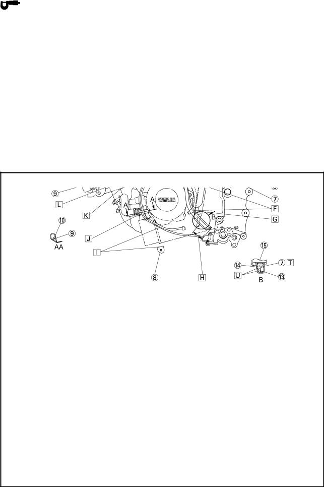
Throttle stop screw
Coolant reservoir tank hose
Cover 8
Radiator fan motor lead (right)
Pickup coil lead
Rear tail/brake light switch lead
Radiator return hose
Coolant hose
Clutch cable
Coolant hose protector
Hose clamp assembly
Hose clamp
 Pass the rear tail/brake light switch lead outside of rear engine mount bolt.
 Pass the ignition coil lead outside of the radiator hose.
 Pass the coolant reservoir tank hose under the frame and right side of the throttle body.
 The tip of the clamp should be pointed to the inside above the vehicle. Items to be clamped here are the radiator fan motor lead (right), coolant reservoir tank hose and radiator return hoses (2 hoses).
 Coupler should be placed within the shaded area of the cover 8. (Extrusion below the shaded area is prohibited.)
 Radiator fan motor lead (right) should be entered into the inside of the vehicle through the frame hole.
 Clamp the clutch cable.
8

CABLE ROUTING |
|
SPEC |
|
|
|
|
|
|
|
|
|
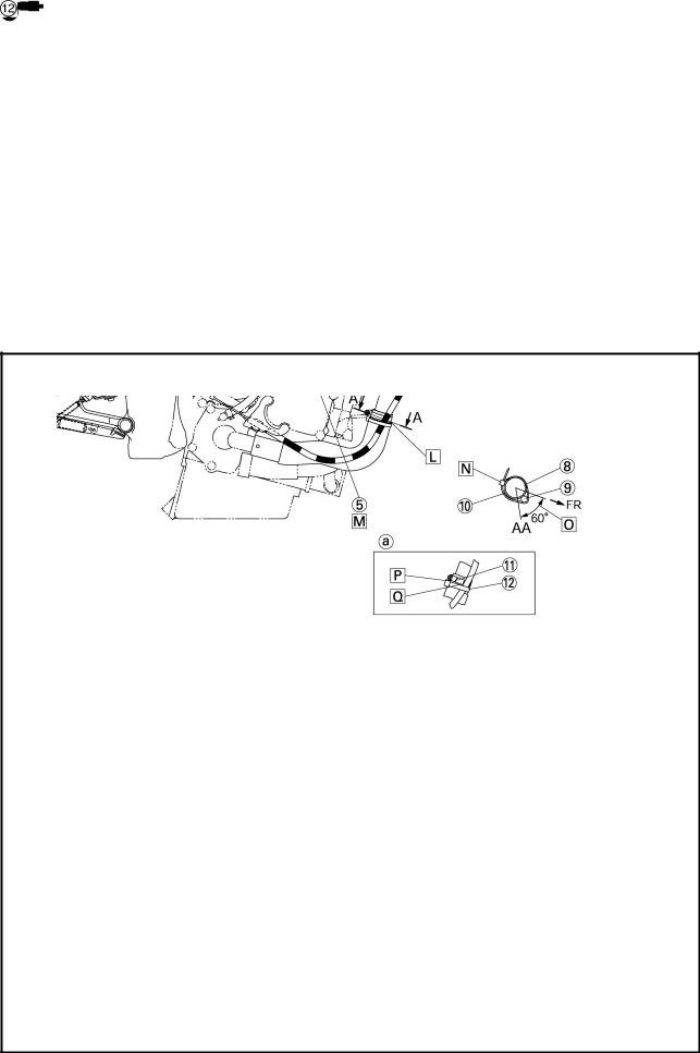
 Route the radiator fan motor lead (right) by the outside of the clutch cable.
 Route the radiator fan motor lead (right) and clutch cable by the inner side of the coolant reservoir tank hose and radiator return hoses (2 hoses).
 The punch mark starting point should be lower than the clamp’s top end.
However, the aiming position of the punch mark starting point should be 5 mm (0.20 in) below the clamp’s bottom end.
 Pass the clutch cable inside of the radiator hose.
 Assemble as “
 ” shown below when clamping.
 Pass the pickup coil lead over the throttle stop cable.
 Tip of the plastic locking tie shall be pointed to the inner side at the rear part of the vehicle.
 Clamp the clutch cable so that it is positioned in this range.
 Put and apply the hose clamp to it.
 Clamp the clutch cable by routing the upper end of the clamp along with the bottom end of the hose clamp assembly.
9

CABLE ROUTING |
|
SPEC |
|
|
|
|
|
|
|
|
|
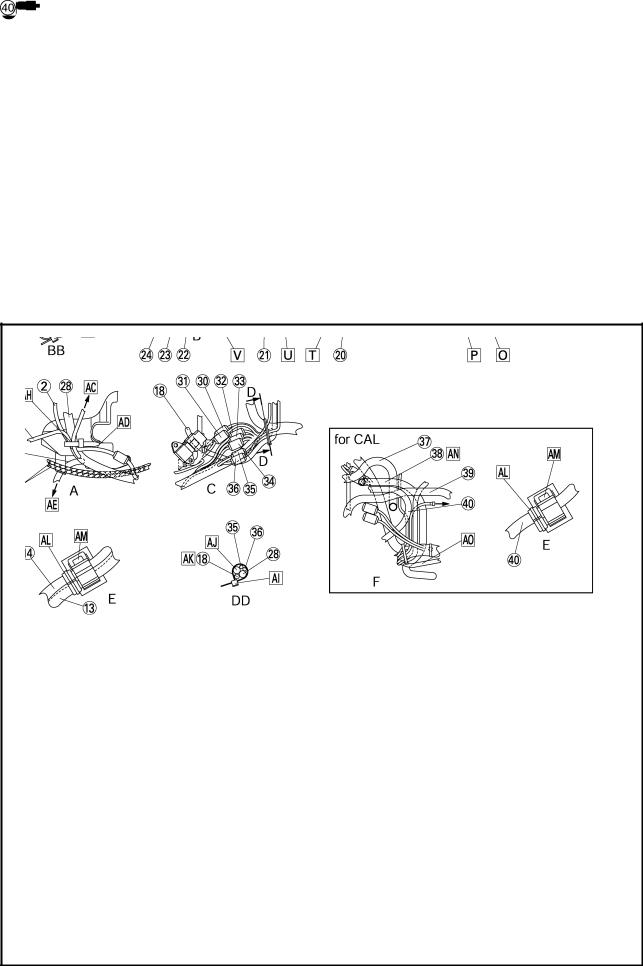
Throttle cable (return side) Throttle cable (pull side) Starter motor lead Canister hose (for CAL) Canister (for CAL) Balance hose (for CAL)
Coolant reservoir tank breather hose Bracket 2
Sidestand switch lead Oil level switch lead A.C. magneto lead
Radiator fan motor lead (left) Fuel tank breather hose Fuel tank drain hose Coolant reservoir tank cover Drive sprocket cover Coolant reservoir tank
 Pass the main switch lead under the left handlebar switch lead and then to the right side of the vehicle.
 Pass the throttle stop cable by the left side of the side stand switch lead, oil level switch lead, A.C. magneto lead and then to the right side of the vehicle.
 Route the A.C. magneto lead, sidestand switch lead and oil level switch lead so that they pass the inner side of the barance pipe 3. (for CAL)
 Pass the fuel tank drain hose and fuel tank breather hose inside of the coolant reservoir tank breather hose, coolant reservoir tank hose and wire harness and then route it by the out side of the starter motor lead.
 Pass the coolant reservoir tank hose outside of the fuel tank drain hose and fuel tank breather hose.
10
CABLE ROUTING |
|
SPEC |
|
|
|
|
|
|
|
|
|
 Pass the fuel tank drain hose, fuel tank breather hose through the clamp of the coolant reservoir tank.
 Pass the coolant reservoir tank breather hose through the clamp of under the coolant reservoir tank.
 Projection allowance from the coolant reservoir tank cover shall be 30 to 50 mm (1.18 ~ 1.97 in).
 Pass the oil level switch lead and sidestand switch lead over the bracket 2.
 Pass the oil level switch lead, and sidestand switch lead through the clamp.
 5 ~ 45 mm (0.20 ~ 1.77 in).
 Clamp the A.C. magneto lead, oil level switch lead and sidestand switch lead.
 Pass the sidestand switch lead, oil level switch lead and A.C. magneto lead between the engine stay and the engine.
 To the throttle body
 To the radiator fan motor relay and fuse box
 Route the radiator fan motor lead (left) by the outside of the radiator inlet hose.
 Pass the throttle cable between the guide of the cover 2 and the frame.
 Pass the radiator fan motor lead (left) through the hole of the frame to the inner side of the vehicle.
 To the horn
 Pass the coolant reservoir tank breather hose through the hole of the coolant reservoir tank cover.
 Order of ups and downs means no object.
  Route it below the coolant reservoir tank.
11

CABLE ROUTING |
SPEC |
|
|
|
|
||
|
|
|
|
Right handlebar switch lead Radiator fan motor lead (right) Sub wire harness
Headlight lead Meter lead Cover 8 Ignition coil lead
Throttle position sensor coupler Coolant reservoir tank hose Throttle stop cable
Speed sensor lead coupler Crankshaft position sensor lead coupler
 Fuel tank breather hose (except for CAL)
 Fuel tank drain hose (except for CAL)
 Fuel hose (return side, except for CAL)
Fuel pump 2 coupler Fuel pump 1 coupler Starter motor lead
Fuel hose (feed side, except for CAL)
Crankcase breather hose Throttle air vent hose Fuse box
Cover 7
Radiator fan motor relay Radiator fan motor lead (left) Left handlebar switch lead
Main switch lead Wire harness Throttle cables
Throttle sub-lead 1 (white 6 poles)
 Throttle sub-lead 2 (black 6 poles)
 Oil level switch lead coupler (white 1 pole)
 Sidestand switch lead coupler (blue 2 poles)
 A.C. magneto lead coupler (white 3 poles)
 Rear tail/brake light switch lead coupler (brown 2 poles)
12
CABLE ROUTING |
|
SPEC |
|
|
|
|
|
|
|
|
|
Neutral switch lead coupler (connector 1 pole) Fuel hose (return side, for CAL)
Canister hose (for CAL)
Fuel hose (feed side, for CAL) Fuel tank drain hose (for CAL)
 To the headlight
 Make sure not to drop the headlight sub wire harness beneath the projection of the duct. Check it when installing the side cowling.
 Clamp the plastic locking tie to the cover 8. Place the coupler at the rear side of the vehicle against the plastic locking tie. Point the tip of the plastic locking tie to the downward in the inner side of the vehicle.
 Route the headlight and meter leads under the frame’s lower part from the hollow section of the cover 2.
 Pass the left and right handlebar switch leads outside of the air filter case air vent hose.
 Connect the couplers (4 units) at the frame side hole. Do not catch each lead and wire harness when the cover 8 is attached.
 From the radiator
 Pass the coolant reservoir tank hose through forward the starter motor lead and speed sensor lead.
 Pass the speed sensor lead coupler and crankshaft position sensor lead coupler over the throttle stop cable.
13
Loading...