


SPECIFICATIONS
A. GENERAL SPECIFICATIONS |
|
|
||
|
|
|||
Basic color |
Crystal Silver |
|||
Dimensions: |
2180mm |
(85.8 in.) |
||
Overall length |
||||
Overal I width |
835mm |
(32.9 in.) |
||
Overall height |
1150mm |
(45.3 in.) |
||
Seat height |
810mm |
(31.9 in.) |
||
Wheelbase |
1465mm (57.7 in.) |
|||
Minimum ground clearance |
145mm |
(5.7 in.) |
||
Caster |
(steering head angle) |
27° |
||
TraiI |
|
110mm |
(4.3 in.) |
|
|
|
|
|
|
Weight: |
|
229 kg |
(505 Ibs.) |
|
Net |
|
|||
Engine: |
|
_ _ _ _ _ _ _ _ ~ ~ |
||
|
D.O.H.C.,air-cooled,triple |
|||
Type |
|
68mm x 68.6mm x 3 |
||
Bore x stroke x cylinders |
||||
747cc |
|
|||
Displacement |
|
|||
8.5: 1 |
|
|||
Compression ratio |
|
|||
142 Ibs in² (±14 Ibs in²) |
||||
Compression pressure (warm engine) |
||||
Lubrication: |
Pressure lubricated, wet sump |
|||
Lubrication system |
||||
Delivery pump type |
Trocoid |
|
||
|
|
|
||
Carburetion: |
Mikuni |
|
||
Manufacture |
|
|||
Type, |
I.D. No., Quantity |
BS34, constant velocity, 1J701, 3 pcs. |
||
Rated venturi size |
34mm |
|
||
|
|
|
||
Air filter |
|
Dry foam rubber |
||
|
|
|
|
|
Ignition: |
|
Battery/coiI |
||
Type |
|
|||
Spark plug |
NGK BP-7ES, Champion N-7Y |
|||
|
|
|
|
|
Charging |
|
Three-phase, regulated alternator |
||
Type |
|
|||
Manufacture, I.D. No. |
Hitachi LD120-02 |
|||
Maximum output |
14.5 Volt/l8 amp |
|||
Battery type |
12 volt |
14amp-hour |
||
Battery dimensions |
134 x 166 x 89mm |
|||
Regulator |
Hitachi TL1Z-80 |
|||
Rectifier |
Stanley DE-4404, Silicon, full wave |
|||
|
|
|
||
Starting |
|
Transmission coupled kick |
||
|
|
Mitsuba Electric SM-224C |
||
|
|
|
||
Primary drive |
Hy-Vo silent chain |
|||
Type |
|
|||
Teeth, ratio |
45/27 |
1.666 |
||
|
|
|
||
Clutch |
|
Wet, multiple disc. |
||
|
|
|
|
|
|
|
|
|
|
|
|
|
|
|
|
|
|
|
|
|
|
|
|
|
|
|
|
|
|
Transmission: |
|
Constant mesh, 5-speed, drum shifter |
|
|||
|
|
|
|
|
|||
|
Teeth, ratio, overall |
1st |
32/13 |
2.461 |
13.285 |
|
|
|
|
|
2nd |
27/17 |
1.588 |
8.636 |
|
|
|
|
3rd |
26/20 |
1.300 |
7.069 |
|
|
|
|
4th |
1 |
1.095 |
5.955 |
|
|
|
|
5th |
22/23 |
0.956 |
5.201 |
|
|
Secondary Drive: |
|
|
|
|
|
|
|
Transmission 0utput: |
|
Shaft drive |
|
|
||
|
|
|
|
|
|
||
|
Type, teeth, ratio |
|
Spur gear, 34/32, 1.063 |
|
|||
|
Middle gear case |
|
|
|
|
|
|
|
Type, teeth, ratio |
|
Bevel gear, 19/18, 1.056 |
|
|||
|
Final gear case |
|
|
|
|
|
|
|
Type, teeth, ratio |
|
Bevel gear, 32/11, 2.909 |
|
|||
|
|
|
|
|
|
|
|
|
Chassis: |
|
|
|
|
|
|
|
Frame |
|
|
Tubular steel double cradle |
|
||
|
Suspension: |
|
Telescopic fork, 175mm (6.9 in.) |
|
|||
|
Front |
(type, travel) |
|
||||
|
Rear |
(type, travel) |
Swing arm, 75mm |
(3.0 in.) |
|
||
|
Tires: |
|
|
|
|
|
|
|
Front |
|
|
3.25 H 19 Bridgestone |
|
||
|
Rear |
|
|
4.00 H 18 Bridgestone |
|
||
|
Brakes: |
|
|
|
|
|
|
|
Front |
|
|
Dual hydraulic disc |
|
|
|
|
Rear |
|
|
Single hydraulic disc |
|
||
|
Fuel tank |
|
|
|
US gal.) |
Regular leaded or unleaded |
|
|
Wheels: |
|
|
1.85 x 19 Cast Aluminum |
|
||
|
Front |
|
|
|
|||
|
Rear |
|
|
2.15 x 18 Cast Aluminum |
|
||
|
|
|
|
|
|
|
|
B. MAINTENANCE SPECIFICATIONS
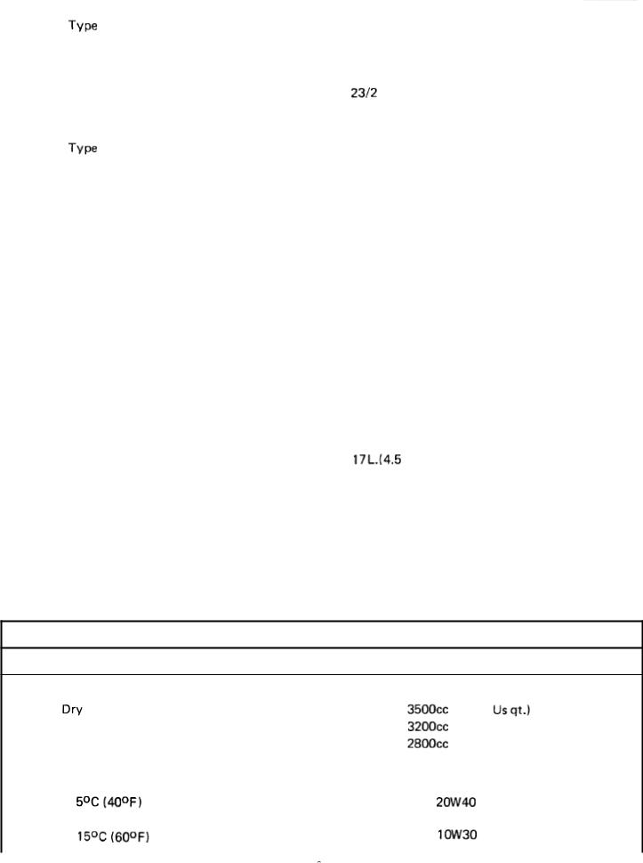
1. Engine
Engine Oil Capacity |
|
|
|
|
|
|
(3.7 |
Oil and filter change |
|
|
(3.4 US qt.) |
Oil change |
|
|
(3.0 US qt.) |
Recommended Iubricant : |
|
|
|
If temperature does not go below |
|
|
|
|
|
SAE |
SE motor oil |
If temperature does not go above |
|
SAE |
SE motor oil |
|
|
||
|
|
|
|
|
|
|
|
|
Middle gear case capacity: |
375cc ( 13 oz.) |
|
|
Final Gear case capacity |
300cc (100 oz.) |
|
|
Recommended Iubricant |
|
|
|
If temperature does not go below |
SAE 90 Hypoid gear oil, G L-4 |
|
|
5°C (40°F) |
|
|
|
If temperature does not go above |
SAE 80 Hypoid gear oil, GL-4 |
|
|
15°C (60°F) |
|
|
|
A II weather |
SAE 80W90 Hypoid gear oil, GL-4 |
|
|
|
|
|
|
Cranking pressure (at sea level) |
10 ± 1 kg/cm² (142 ± 14 psi) |
|
|
Maximum difference between cylinders |
1 .0 kg/cm² (14 psi) |
|
|
|
|
|
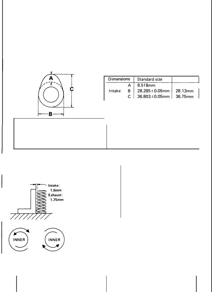
Camshafts
I
Camshaft bearing surface diameter Camshaft-to-cap clearance:
Standard
Maximum Camshaft runout limit
Wear Iimit
|
|
A |
8.018mmm |
|
------------- |
|
|
|
|
Exhaust B |
28.285 |
±0.05mm |
|
28.13mm |
|
|
|
C |
36.303 |
± 0.05mm |
|
36.15mm |
|
|
|
|
|
|
|
|
|
|
|
24.97~24.98mm (0.9830~0.9835 in.) |
|
||||
|
|
.020~.054mm (.0008~.002 |
in.) |
|
|||
|
|
.160mm (.006in.) |
|
|
|||
|
|
0.1mm (.004 in) |
|
|
|
I |
|
|
Valves |
|
|
|
|
|
|
|
|
|
|
|
|
|
||
|
|
|
|
|
I |
|
INNER |
OUTER |
|
|||||||
|
|
|
|
|
|
|
|
|
|
|||||||
|
|
|
|
|
|
|
|
|
|
INTAKE/EXHAUST |
INTAKE/EXHAUST |
|
||||
|
|
|
ALLOWABLE TILT |
|
|
|
|
|
|
|
|
|
|
|
||
|
|
|
Free length |
|
|
|
|
35.6mm |
39.9mm |
|
||||||
|
|
|
FROM VERTICAL |
|
|
|
|
|
|
|
|
|
|
|
|
|
|
Spring rate (kg/mm) |
|
|
|
|
K1 |
1.84 |
K1 3.32 |
|
|||||||
|
|
|
|
|
|
|
|
|
|
|||||||
|
|
|
|
|
|
|
|
|
|
|
K2 |
2.36 |
K2 4.18 |
|
||
|
|
|
|
|
|
|
|
|
|
|
|
|
|
|
|
|
|
|
|
|
|
Installed length |
|
|
|
|
|
|
|
|
|
|
|
|
|
|
|
|
(valve closed) |
|
|
|
|
31.5mm |
34.5mm |
|
||||
|
|
|
|
|
|
|
|
|
|
|
|
|
|
|
|
|
|
|
|
|
|
Installed pressure |
1 |
|
|
|
|
|
|
|
|
||
|
OUTER |
OUTER |
(valve closed) |
|
|
7.5 ± 0.75kg |
17.5 ± 1.2kg |
|
||||||||
|
|
|||||||||||||||
|
Compressed length |
|
|
|
|
|
|
|
|
|
|
|||||
|
|
|
|
|
|
|
|
|
|
|
|
|
|
|
||
|
|
|
|
|
(valve open) |
|
|
|
|
23.0mm |
26.0mm |
|
||||
|
|
|
|
|
|
|
|
|
|
|
|
|
|
|
|
|
|
|
|
|
|
Wire diameter |
|
|
|
|
2.8mm |
3.9mm |
|
||||
|
|
|
|
|
|
|
|
|
|
|
|
|
|
|
||
|
INTAKE |
EXHAUST |
Number of windings |
|
|
|
7.75 |
6.4 |
|
|
||||||
|
|
|
|
|
||||||||||||
|
|
|
|
|
|
|
|
|
|
|
|
|
||||
|
DIRECTION OF WINDINGS |
Winding O.D. |
|
|
|
|
15+ 0.3mm |
21.6 0 |
|
|
||||||
|
(TOP TO BOTTOM) |
|
|
|
|
|
|
|
0 |
|
- 0.3mm |
|
||||
|
|
|
|
|
|
|
|
|
|
|
|
|
|
|
|
|
|
|
I |
|
|
I |
|
|
|
|
|
|
|
1 |
|
||
|
|
|
Valve stem run-out maximum |
|
|
|
|
.03mm (.0012 in.) |
|
|
|
|
||||
|
|
|
Valve seat width standard/maximum |
|
|
|
|
1.3mm (.050 in.) / 2.0mm (.080 in.) |
|
|
||||||
|
|
|
|
|
|
|
|
|
|
|
|
|
|
|
|
|
|
|
|
|
|
|
|
|
|
|
|
|
|
|
|
|
|
|
|
|
|
|
|
|
|
|
|
|
|
|
|
|
|
|
|
|
|
|
|
|
|
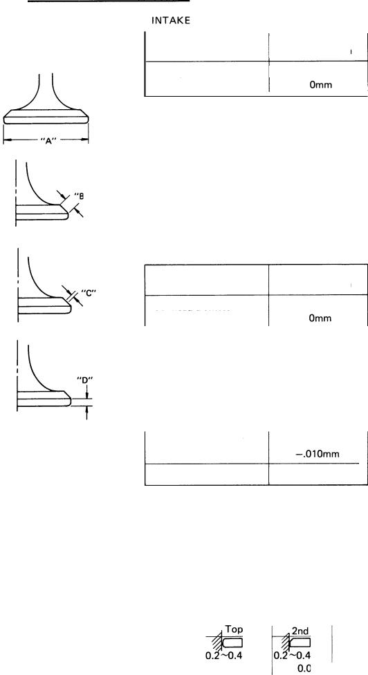
CIearance |
|
|
0.16~0.20mm |
|
||||||||
|
|
|
|
|
(Cold engine) |
|
|
|
|||||||||
|
|
|
|
|
"A" head diameter |
|
|
36 + 0.2 |
|
|
|||||||
|
|
|
|
I "B" face width |
|
|
2.26 ± 0.57mm |
|
|||||||||
|
|
|
|
|
"C" |
seat width |
|
|
1.3 ±0.15mm |
|
|
||||||
|
|
|
|
|
|
|
|
|
|
|
|
|
|
|
|||
|
|
|
|
|
"D" |
margin thickness |
|
|
1.2±0.2mm |
|
|
||||||
|
|
|
|
|
Stem diameter (O.D.) |
|
|
7 + .010mm |
|
|
|||||||
|
|
|
|
|
|
|
|
|
|
|
|
|
|
-.025mm |
|
|
|
|
|
|
|
|
Guide diameter (I.D.) |
|
|
7 + .019mm |
|
|
|||||||
|
|
|
|
|
|
|
|
|
|
|
|
|
|
-.010mm |
|
|
|
|
|
|
|
|
|
|
|
|
|
|
|
|
|
||||
|
|
|
|
|
I Stem-to-guide clearance |
|
I |
0.020~0.041mm I |
|
|
|||||||
|
|
|
|
|
EXHAUST |
|
|
|
|
|
|
|
|||||
|
|
|
|
|
CIearance |
|
|
0.2 1~0.25mm |
|
||||||||
|
|
|
|
|
(Cold engine) |
|
|
|
|||||||||
|
|
|
|
|
"A" head diameter |
|
|
31 + 0.2mm |
|
||||||||
|
|
|
|
|
|
|
|
|
|
|
|
|
|
||||
|
|
|
|
|
"B" face width |
|
|
2.26 ± 0.57mm |
|
|
|||||||
|
|
|
|
|
|
|
|
|
|
|
|
|
|
|
|||
|
|
|
|
|
"C" |
seat width |
|
|
1.3 ± 0.15mm |
|
|
||||||
|
|
|
|
|
|
|
|
|
|
|
|
|
|
|
|||
|
|
|
|
|
"D" |
margin thickness |
|
|
1.2± 0.2mm |
|
|
||||||
|
|
|
|
|
Stem diameter (O.D.) |
|
|
7 +.025mm |
|
|
|||||||
|
|
|
|
|
|
|
|
|
|
|
|
|
|
-.040 mm |
|
|
|
|
|
|
|
|
|
|
|
|
|
|
|
|
|
||||
|
|
|
|
|
Guide diameter (I.D.) |
|
|
7 + .019mm |
|
||||||||
|
|
|
|
|
Stem-to-guide clearance |
|
|
0.035~0.059mm |
|
||||||||
|
|
|
|
|
|
|
|
|
|
|
|
|
|
|
|
||
|
Cylinder and Piston |
|
|
|
|
Aluminum |
|
|
|
|
|
|
|
||||
|
Cylinder material |
|
|
|
|
|
|
|
|
|
|
|
|||||
|
Cylinder liner |
|
|
|
|
Pressed in; |
special cast iron |
|
|||||||||
|
Standard bore sizehtandard |
|
|
|
|
68.00~68.02mm |
/ (2.677~2.678 in.) |
|
|||||||||
|
|
|
maximum |
|
|
|
|
68.10mm (2.681) |
|
|
|
|
|
||||
|
Cylindertaper limit |
|
|
|
|
0.05mm (.002 in.) |
|
|
|
|
|
||||||
|
Cylinder out-of-round limit |
|
|
|
|
0.01mm (.0004 in.) |
|
||||||||||
|
Piston clearancehtandard |
|
|
|
|
0.050~0.055mm / (.0020~.0022 in.) |
|
||||||||||
|
|
|
maximum |
|
|
|
|
0.1mm (.004 in.) |
|
|
|
|
|
||||
|
|
|
|
|
|
|
|
|
|
|
|
|
|
|
|
||
|
Piston Rings |
|
|
|
|
|
|
|
|
|
Oil |
|
|||||
|
Design |
|
|
|
|
|
|
|
|
|
|
|
|
||||
|
End gap (installed) |
|
|
|
|
-0.4mm |
|
|
|
-0.4mm 0.2~0.9mm |
|
||||||
|
Side clearance |
|
|
|
|
0.04-0.08mm |
|
0.03-0.07mm |
|
||||||||
|
|
|
|
|
|
|
|
|
|
|
|
|
|
|
|
|
|
|
|
|
|
|
|
|
Crankshaft and Connecting Rods: |
|
|
|
|
|
Main bearing oil clearance |
0.022~0.044mm |
(.0009~.0017 |
in.) |
|
|
Rod bearing oil clearance |
0.032~0.054mm |
(.0013~.0021 |
in.) |
|
|
Main journal run-out (maximun) |
0.03mm (.0012 in.) |
|
|
|
|
|
|
|
|
|
|
Oil Pump |
|
|
|
|
|
Housing-to-outer rotor clearance |
,090~.015mm (.0035~.0059 in.) |
|
||
|
Outer rotor-to-inner rotor clearance |
.03 ~.09mm (.0011~.0035 in.) |
|
|
|
|
|
|
|
|
|
|
Clutch |
3.0mm (0.12 in.) |
|
|
|
|
Friction plate thickness standard |
|
|
|
|
|
minimum |
2.8mm (0.11 in.) |
|
|
|
|
Clutch plate warp maximum |
0.05mm (.002 in) |
|
|
|
|
Clutch spring length standard |
42.8mm (1.685 in.) |
|
|
|
|
minimum |
41.5mm (1.634 in.) |
|
|
|
|
Clutch push rod run-out maximum |
0.4mm (.016in.) |
|
|
|
|
Clutch lever freeplay (endof lever) |
13~26mm (0.5~1.0 in) |
|
|
|
|
|
|
|
|
|
|
Transmission shaft run-out maximum |
.08mm (.001 in.) |
|
|
|
|
|
|
|
|
|
|
Middle gear case lash |
0.1 ~0.2mm (.004~.008 in.) |
|
|
|
|
|
|
|
|
|
2. Carburetion
Manufacturer |
I |
|
|
Mikuni |
Float level |
26.5 ±2.5mm (from gasket surf |
|
Model, I. D. No. |
BS34,1J701 |
Pilot screw |
2¼ turns |
Main jet |
No. 145 |
Air jet, Main |
1.0mm |
Needle jet |
Y-2 |
Air jet, Pilot |
1.6mm |
Pilot jet |
No. 17.5 |
Throttle valve |
No. 140 |
Starter jet |
No. 45 |
Inlet valve size |
2.0mm |
Jet needles / Clip position |
4H11/3 |
Engine idle speed |
1050~ 1150 r.p.m. |
|
|
|
|

3. Chassis
Wheels and Tires |
|
|
|
|
|
|
|
|
Rim run-out, vertical |
|
|
|
2.0mm (.080 in.) |
||||
Rim run-out, horizontal |
|
|
l.0mm (.040 in.) |
|||||
Tire pressure, front, normal riding |
|
|
1.8 |
(26 p.s.i.) |
||||
High speed or with passenger |
|
|
2.0 kg/cm2 |
(28 p.s.i.) |
||||
Tire pressure, rear, normal riding |
|
|
2.0 kg/cm2 (28 p.s.i.) |
|||||
High speed or with passenger |
|
|
2.3 kg/cm2 |
(33 p.s.i.) |
||||
|
|
|
|
|
|
|
|
|
Brakes |
|
|
|
|
|
|
|
|
Recommendedfluid |
|
|
|
DOT No. 3 |
|
|
|
|
Minimum boiling point |
|
|
240°C (464°F) |
|
|
|
||
Pad thickness wear limit |
|
|
5.5mm (0.18 in.) |
|||||
Brake disc maximum deflection |
|
|
0.15mm (.006 in.) |
|||||
Brake disc minimum thickness |
|
|
6.5mm (0.26 in.) |
|||||
Front brake freeplay (end of lever) |
|
|
5.0~10.0mm |
(0.2~0.4 in.) |
||||
Rear brake freeplay (end of pedal) |
|
|
5.0~10.0mm |
(0.2~0.4 in.) |
||||
|
|
|
|
|
|
|
|
|
Front forks |
|
|
|
|
|
|
|
|
Spring (upper) free length |
|
|
55.8mm (2.2 in.) |
|||||
preload length |
|
|
50.8mm (2.0 in.) |
|||||
Spring (lower) free length |
|
|
448.3mm (17.65 in.) |
|||||
preload length |
|
|
423.3mm (16.67 in.) |
|||||
Spring rate (0~100mm travel) |
|
|
0.5 kg/mm (28 Ibs/in.) |
|||||
(100~175mm travel) |
|
|
0.6 kg/mm (33.6 Ibs./in.) |
|||||
Fork oil capacity (each side) |
|
|
170cc (5.75 US fl. oz.) |
|||||
|
|
|
|
|
|
|
|
|
Rear shock absorbers |
|
|
|
|
|
|
|
|
Spring free length |
|
|
|
253mm (9.95 in.) |
||||
Spring preload length |
|
|
|
228 mm (9.0 in.) |
||||
Spring rate (0~45mm |
travel) |
|
|
1.9 kg/mm |
(106 Ibs./in.) |
|||
(45~75mm |
travel) |
|
|
2.6 kg/mm |
(145 Ibs./in.) |
|||
|
|
|
|
|
|
|
|
|
|
|
|
|
|
|
|
|
|
|
|
|
|
|
|
|
|
|
|
|
|
|
|
|
|
|
|
Ignition timing retarded |
|
|
|
10° @ 1100 rpm |
|
|
|
|
advanced |
|
|
38.5° ± 1.5°@ 2,900 rpm |
|||||
advance starts |
|
|
1550 + 200 rpm |
|
|
|
|
|
|
|
|
|
0 |
|
|
|
|
Spark plug |
|
|
|
NGK BP-7ES or Champion N-7Y |
||||
Electrode gap |
|
|
|
0.7~ 0.8mm (.028~.032 in) |
||||
|
|
|
|
|
|
|
|
|
Spark plug cap resistance |
|
I |
5.0 K ohms |
|
|
|
|
|
Contact point gap |
|
|
|
0.3~0.4mm (.012 ~.016 in) |
||||
Spring tension |
|
|
|
750 ± 100g (26.5 ± 3.5 oz) |
||||
|
|
|
|
|
|
|
|
|
Condenser capacity |
|
|
|
0.22µF ± 10% |
|
|
|
|
Insulation resistance |
|
|
|
10 M ohms or more |
|
|
|
|
|
|
|
|
|
|
|
|
|
Ignition coil type |
|
|
|
Hitachi CM11-52A |
|
|
|
|
Spark gap 6V |
|
|
|
6mm @ 100 rpm |
|
|
|
|
12V |
|
|
|
7mm @ 5,000 rpm |
|
|
|
|
Primary resistance (20°C) |
|
|
4.0 ± 0.4 ohms |
|
|
|
|
|
Secondary resistance (20°C) |
|
|
11.0 ± 1.1K ohms |
|
|
|
||
|
|
|
|
|
|
|
|
|
|
|
|
|
|
|
|
|
Starter motor type |
Mitsuba |
SM-224C |
|
||
|
Armature coil resistance (2O°C) |
0.007 ohms |
|
|
||
|
Field coil resistance (2O°C) |
0.01 ohms |
|
|
||
|
Brush length standard |
12.5mm (0.5 in) |
|
|||
|
minimum |
5.5mm (0.22 in) |
|
|||
|
Brush spring pressure |
620 ± 60g (22.0 ± 2.0 oz) |
|
|||
|
Armature mica undercut |
0.5 ~ 0.8mm (0.02 ~ 0.03 in) |
|
|||
|
|
|
|
|
||
|
Battery type |
Yuasa |
YB 14L |
|
||
|
Charging rate |
1.4 amps for 10 hours |
|
|||
|
|
|
|
|||
|
Generator type |
Hitachi Ld 120-02 |
|
|||
|
No load voltage |
14.5 ± 0.5V |
|
|
||
|
Field (inner) coil resistance(20°C) |
4.04 ± 0.4 ohms |
|
|||
|
Stator (outer) coil resistance (20°C) |
0.48 ± 0.05 ohms |
|
|||
|
|
|
|
|||
|
Regulator type |
Hitachi TLIZ-80 |
|
|||
|
Regulated voItage |
14.5 ± 0.5V |
|
|
||
|
Core gap |
0.6 ~ 1 .0mm (.024 ~.040 in) |
|
|||
|
Yoke gap |
0.9mm (.035 in) |
|
|||
|
Point gap |
0.3 ~ 0.4mm |
(.012 ~.016 in) |
|
||
|
|
|
|
|
||
|
Starter relay switch |
Hitachi |
A104-70 |
|
||
|
Cut-in voltage |
6.5 V |
|
|
|
|
|
Winding resistance (20°C) |
3.5 ohms |
|
|
|
|
|
|
|
|
|
|
|
|
Lighting |
Sealed beam |
12V50/40W |
|
||
|
Headlight |
|
||||
|
TaiIIight/stopIight |
12V |
8/27W |
(two bulbs) |
|
|
|
License light |
12v |
8W |
|
|
|
|
Flasher Iight |
12V |
27W |
(four bulbs) |
|
|
|
Flasher pilot light |
12V |
3.4W |
(two bulbs) |
|
|
|
Meter Iights |
12V |
3.4W |
(two bulbs) |
|
|
|
High beam indicator light |
12v 3.4w |
|
|
||
|
Oil pressure warning light |
12v |
3.4w |
|
|
|
|
Neutral light |
12v |
3.4w |
|
|
|
|
|
|
|
|
|
|

|
C. |
Torque Specifications |
|
|
|
|
|
|
I |
Engine |
|
|
1.5 ~ 2.5 m-kg (11.0 ~18.0 ft-lbs.) |
|
|
|
|
|
|||||
|
|
Spark plug |
|
|
|
||
|
|
Cam cap nut |
|
|
0.8 |
~ 1.Om-kg (6.0 ~ 7.0 ft-lbs.) |
|
|
|
Rod cap |
|
|
3.8 m-kg (27 ft-lbs.) |
|
|
|
|
Starter clutch bolt |
|
2.8 |
~ 3.2 m-kg (20 ~ 23 ft-lbs.) |
|
|
|
|
Shift cam locating bolt |
|
1.3 ~ 2.1 m-kg (9 ~ 15 ft-lbs.) |
|
||
|
|
Detent assembly |
|
4.0 |
~ 4.5 m-kg (29 ~ 32 ft-lbs.) |
|
|
|
|
Transmission bearing caps |
|
1.8 ~ 2.2 m-kg (13 ~ 16 ft-lbs.) |
|
||
|
|
Crankcase bolts |
8mm |
|
2.0 rn-kg (14 ft-lbs.) |
|
|
|
|
|
10mm |
|
3.7 m-kg (27 ft-lbs.) |
|
|
|
|
Clutch holding nut |
|
8 m-kg (58 ft-lbs) |
|
||
|
|
Clutch spring screws |
|
0.8 ~ 1.Om-kg (6.0 ~ 7.0 ft-lbs.) |
|
||
|
|
Middle gear case mounting screws |
|
2.0 |
~ 2.5 m-kg (14 ~ 18 ft-lbs.) |
|
|
|
|
Rotor holding bolt |
|
3.0 ~ 4.0 m-kg (22 ~ 29 ft-lbs.) |
|
||
|
|
Bearing housing bolt |
|
2.0 ~ 2.4 m-kg (14 ~ 17 ft-lbs.) |
|
||
|
|
Oil pipe union bolt |
|
2.0 |
~ 2.2 m-kg (14 ~ 16 ft-lbs.) |
|
|
|
|
Oil pump drive gear nut |
|
8.0 ~ 12.0 m-kg (58 ~ 87 ft-lbs.) |
|
||
|
|
Crankshaft turning nut |
|
1.5 ~ 2.9 m-kg (11 ~ 21 ft-lbs.) |
|
||
|
|
Cylinder head |
8mm |
|
2.0 m-kg (14 ft-lbs.) |
|
|
|
|
10mm |
|
3.5 m-kg (25 ft-lbs.) |
|
||
|
|
Cylinder holding nuts |
|
2.0 m-kg (14 ft-lbs.) |
|
||
|
|
Camshaft cap nuts |
|
1.O m-kg (7 ft-lbs.) |
|
||
|
|
Engine mounting bolts 10mm |
|
5.0 |
~ 6.0 m-kg (36 ~ 43 ft-lbs.) |
|
|
|
|
|
12mm |
I |
8.0 ~ 11.0 m-kg (58 ~ 80 ft-lbs.) |
|
|
|
|
Engine oil drain plug |
|
3.9 ~ 4.7 m-kg (28 ~ 34 ft-lbs.) |
|
||
|
|
Oil filter mounting bolt |
|
3.0 |
~ 3.4 m-kg (22 ~ 25 ft-lbs.) |
|
|
|
|
Middle gear drain plug |
|
3.9 |
~ 4.7 m-kg (28 ~ 34 ft-lbs.) |
|
|
|
|
Chassis |
|
|
7.0 ~ 10.0 m-kg (50 ~ 72 ft-lbs.) |
|
|
|
|
Front axle nut |
|
|
|
||
|
|
Front axle holder nuts |
|
1.3 ~ 2.3 m-kg (9 ~ 17 ft-lbs.) |
|
||
|
|
Rear axle nut |
|
|
12.0 ~ 18.0 m-kg (87 ~ 130 ft-lbs.) |
|
|
|
|
Rear axle pinch bolt |
|
0.45 ~ 0.75 m-kg (3.0 ~ 5.0 ft-lbs.) |
|
||
|
|
Brakes |
|
|
1.5 ~ 2.0 m-kg (11 ~ 15 ft-lbs.) |
|
|
|
|
Caliper support bolt |
|
|
|||
|
|
Caliper mounting bolt |
|
4.5 ~ 5.0 m-kg (28 ~ 35 ft-lbs.) |
|
||
|
|
Brake hose union bolt |
|
2.3 ~ 2.8 m-kg (16 ~ 20 ft-lbs.) |
|
||
|
|
Disc mounting bolt |
|
1.7 |
~ 2.2 m-kg (12 ~ 16 ft-lbs.) |
|
|
|
|
Front fork pinch bolt |
|
1.3 |
~ 2.3 m-kg (9 ~ 17 ft-lbs.) |
|
|
|
|
Steering stem top bolt |
|
6.6 ~ 10.5 m-kg (48 ~ 76 ft-lbs.) |
|
||
|
|
Swing arm pivot lock nut |
|
8.0 ~ 10.0 m-kg (58 ~ 72 ft-lbs.) |
|
||
I |
|
Rear shock absorber nut |
1 |
2.3 ~ 3.7 m-kg (20 ~ 27 ft-lbs.) |
|
||
|
|
|
|
|
|
||
Componentsshould be  room temperature.
500 - 600
SPECIAL TOOLS
Valve guide remover |
Clutch holding tool |
Final drive gear holding tool |
Valve guide installer |
Clutch plate installation tool |
Middle and final gear holding tool |
Valve spring compressor |
Clutch lock nut wrench |
Damper special tool |
Valve seat cutter set |
Cam chain cutter |
Rotor puller |
Tappet adjusting tool |
Slide hammer |
Rotor holding tool |
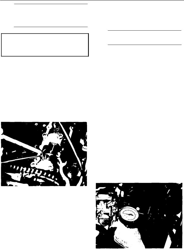
Vacuum gauge |
Gear lash measurement tool |
Gear lash measurement tool |
|
(middle gear) |
(final gear) |

d.Turn petcocks to "prime" position.
e.Start motorcycle and allow it to warm up for 2-3 minutes. The warm-up is complete when engine responds normally to threttle opening.
f.Adjust damping valve on each vacuum gauge until the needle flutters only slightly. The gauge needles must respond quickly to rapid opening of the throttle.
g.Each gauge will indicate the same reading if the carburetors are synchronized. The left and right carburetors are to be synchronized to the center carburetor, which has no synchronizing screw. Turn the left carburetor synchronizing screw until the gauge reading is the same as for the center carburetor. Repeat for the right carburetor.
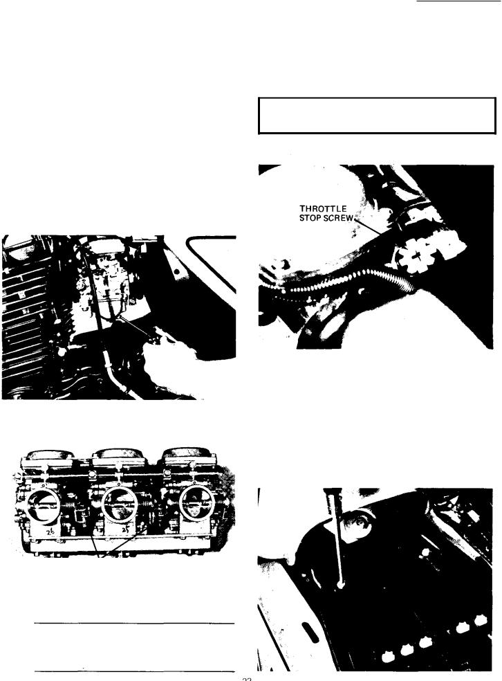
a.The engine must be warmed up before setting idle speed.
b.Set engine idle speed by turning the throttle stop screw in (to increase engine speed) or out (to decrease speed).
Standard Idle RPM
1,050 - 1,1 50rpm
B.Air Filter
1.Removal
a. Lift the seat and remove the air filter case cap by removing the pan head screws (2).
-_-
SYNCHRONIZING SCREWS
3.Idle speed adjustment.
NOTE: Carburetors must be synchronized before setting final idle speed. The idle speed adjustment is made by turning only one throttle stop screw.
b. Pull out the element. |
C. Engine/TransmissionOil |
1. Oil level measurement
a. To check the level, warm the engine up for several minutes. Stop the engine. With the engine stopped, screw the dip stick completely out and then rest the stick in the hole.
2.Cleaning method
a.Tap the element lightly to remove most of the dust and dirt; then blow out theremainingdirt with compressed air through the inner surface of the element. If element isdamaged, replace.
NOTE: When checking engine oil level with the dip stick, let the unscrewed dip stick rest on the case threads. Be sure the engine is stopped and the machine is positioned straight up and on both wheels.
b.The dip stick has a Minimum and a Maximum mark. The oil level should be betweenthe two.
If the level is low, add sufficient oil to raise it to the proper level.
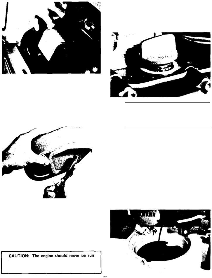
2.Engine/Transmission oil and oil filter replacement
a.Start the engine. Allow it t o warm up for minutes. Stop the engine.
b.Place an oil pan under the engine and remove the oil filler cap.
c.Remove the drain plug and drain the oil.
b. Reassemble by reversing the removal procedure. Check whether the element is seated completely against the case.
c. The air filter element should be cleaned once a month or every 1,600km (1,000 miles). It should be cleaned more often if the machine is operated in extremely dusty areas.
without the air cleaner element installed. Ex- cessive oil contamination and engine wear may result.

d. Remove the oil filter bolt and filter element.
|
|
|
|
|
|
h. After |
replacement of engine |
oil, and/or oil |
|
|
|
|
|
|
|
filter, |
be sure to check the oil pressureand oil |
||
|
|
|
|
|
|
leakage. The oil pressure indicator lightshould |
|||
|
e. Reinstall the drain plug (make sure it istight). |
go off after the engine is started. |
|||||||
|
|
|
|
|
|||||
|
|
|
|
|
|
CAUTION: |
If the "Oil" indicator light |
||
|
|
|
|
|
|
remains |
on, |
immediately stop |
the engine. |
|
|
4.0 ~ 4.5m-kg (28.9-32.5ft-lb) |
|
Refer t o lubrication information |
in Sec. 3-5 |
||||
|
f. Install the oil filter element andcover. Tighten |
|
|
|
|
||||
|
the oil filter bolt. |
D. Middle Gear/Final Gear Oil |
|
||||||
|
|
|
|
|
|
||||
|
|
NOTE: Make sure the " 0 ' ring is positioned |
1. Oil level measurement |
|
|||||
|
|
properly. |
|
|
|
|
|||
|
|
|
|
|
|
a. Place the machine on a level surface and place |
|||
|
|
|
|
|
|
||||
|
|
|
|
|
|
it on the center stand. The engine should be |
|||
|
|
|
|
|
|
cool (at atmospheric temperature). Allow 2 |
|||
|
|
|
|
|
|
minutes for oil to drain to bottom of cases. |
|||
|
|
|
|
|
|
b. Remove the oil filler cap. Check the oil level |
|||
|
|
|
|
|
|
with |
level gauge (from tool kit) as shown. |
||
|
|
|
|
|
|
The correct oil level is between the two marks |
|||
|
|
|
|
|
|
on each end of the level gauge. Use end of |
|||
|
|
|
|
|
|
gauge marked "REAR" for measuring the |
|||
|
|
|
|
|
|
rear |
(final) gear case. Use the end marked |
||
|
|
|
|
|
|
|
|
measuringthe middlegear case. |
|
NOTE: Middle gear and final gear oil can be checked with same level gauge, which is in the owners tool kit.
g. Add oil through the dip stick hole.
Oil quantity: Periodic Oil Change 2.8 liter (3 US qt)
With oil filter change: 3.2 liter (3.4 US qt)
Recommended oil: except in cold weather Yamalube 4-cycle or SAE 20W40 "SE" (see page 8 )

CAUTION: Take care not to allow foreign material t o enter the middle and/or final aear case.
2.Gear oil replacement
a.Place an oil pan under the transmission for the middle gear and under the final gear case.
b.Remove the middle and/or final gear oil filler cap(s) and the drain plug(s), and drain the oil.
not to allow foreign material to enter the middle andlor final gear case. Do not allow the gear oil to contact the tire and wheel.
c. Reinstallthe middle and/or final drain plug(s).
d. Fill the gear case(s) up to specified level.
Oil Capacity: |
375cc (12.7 |
US. fl 02) |
Middle gear case: |
||
Final gear case: |
300cc (10.0 |
U.S. fl 02) |
Recommended oil: |
(see page 8 ) |
|
|
|
|
e. Reinstall the filler cap(s) securely.
NOTE: After initial 250 mile oil change, it is normally not necessary to change middle and final gear oil more frequently than the indicated service interval of 6,000 miles.
E. Clutch Adjustment
This model has a clutch cable length adjustor and a clutch mechanism adjustor. The cable length adjustor5 are used to take up slack from cable stretch and to provide sufficient free play for properclutch operation under various operating conditions. The clutch mechanism adjustor is used to provide the correct amount of clutch "throw" for proper disengagement. Normally, once the mechanism is properly adjusted, the only adjustment required is maintenance of free play at the clutch handle lever.
1.Free play adjustment
Loosen either the handle lever adjustor lock nut or the cable length adjustor lock nut. Next, turn the length adjustor either in or out until proper lever free play is achieved.
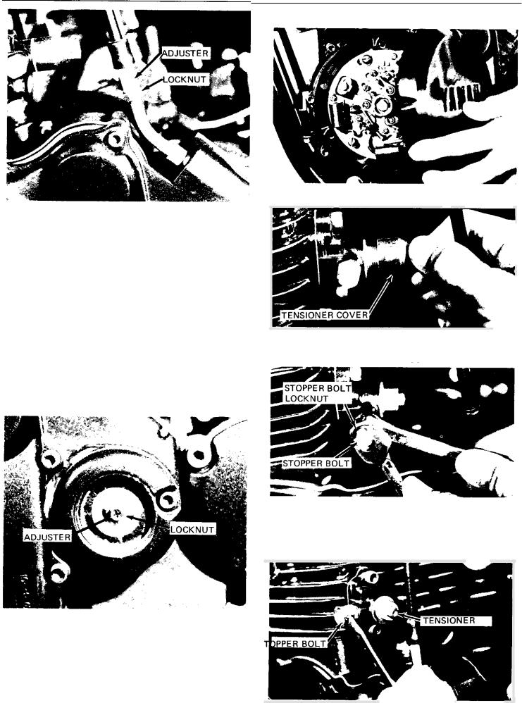
2. Mechanism adjustment
The second adjustment is located behind the adjusting cover. Removing the cover will expose the adjusting set screw and lock nut. Loosen the lock nut and rotate the set screw in until it lightly seats against a clutch push rod that works with the set screw to operate the clutch. Back the set screw out ¼ turn and tighten the lock nut. This adjustment must be checked because heat and clutch wear will affect this free play, possibly enough to cause improper clutch operation. Recheck clutch cable adjustment a t handlebar after adjusting.
1. Remove the breaker cover
2.Remove the cam chain tensioner cover.
Loosen the tensioner stopper bolt lock nut and then loosen the stopper bolt.
4. Slowly rotate the crankshaft counterclockwise several turns. When the tensioner gets deepest into the tensioner holder, tighten the stopper bolt and secure it with the lock nut.
F. |
Cam Chain Adjustment |
S |
|
|
|||
|
|||
|
|||
|
|||
|
|||
|
|
The cam chain becomesstretched with use, resulting in improper valve timing and engine noise. To prevent this the cam chain tensioner must be adjusted regularly.

5.Reinstall the chain tensioner cap and the contact breaker cover.
G.Valve Clearance Adjustment
NOTE: Valve clearance must be measured with the engine a t room temperature.
1.Remove gas tank.
2.Removeair scoop on cylinder head
3.Removecylinder head cover and breaker point cover. Care should be taken to not scratch or
damage gasket sealing surfaces.
4.Turn crankshaft with nut on left end ofcrankshaft to turn cams. The proper position of the cam when measuring valve clearance is with the cam lobe directly opposite the valve lifter.
5.Insert a feeler gauge between the valve lifter and the cam heel.
Exhaust valve clearance (cold) 0.21 - 0.25mm (.008 -.010")
Intake valve clearance (cold)
0.16 - 0.20mm (.006- ,008")
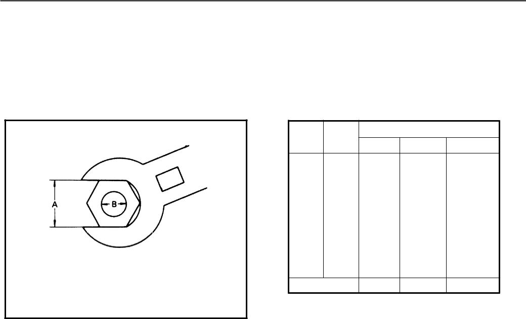
Adjustment
Valve clearance is adjusted by replacing the adjusting pad on the top of the valve lifter. Adjusting pads are available in 25 thicknesses ranging from No. 200
(2.00mm) to No. 320(3.20mm) in steps of 0.05mm. The thickness of each pad is marked on the pad face that contacts the valve lifter (notthe cam). Adjustment of valve clearance is accomplished as follows:
1.Determine valve clearance (feeler gauge measurement.
2. Remove adjusting pad and note number.
3.Select proper pad from appropriate chart (intake or exhaust chart).
4.Install new pad and check installed clearance.
Procedure
1.Measure valve clearance. If clearance is incorrect, record the measured amount of clearance. This must be measured carefully.
2.There is a slot in the valve lifter. This slot must
be positioned opposite the blade of the tappet adjusting tool before the tool is installed.
3.Turn the cam until the lobe fully depresses the valve lifter and opens the valve. Install the tappet adjusting tool as shown to hold the lifter in this depressed position.
ADJUST ING
TOOL,
CYLINDER
PAD REMOVAL SLOT
NOTE: The tappet adjusting tool is fastened to the cylinder head using one (1 ) allen screw such as one used to install the cylinder head cover. Make sure that the tool contacts the lifter only, and not the pad.
CAUTION: If the cam lobe touches the tappet adjusting tool, the stress may fracture the cylinder head. DO NOT ALLOW THE CAM T O CONTACT THE TAPPET ADJUSTING TOOL.
4.Carefully rotate the cam so that the pad can be removed. To avoid cam touching adjusting tool, turn cams as follows: (view from left side of machine)
Intake: Carefully rotate CLOCKWISE. Exhaust: Carefully rotate COUNTERCLOCKWISE.
5.Remove the pad from the lifter. There is a slot in the lifter. Use a small screwdriver or other blade and a magnetic rod to remove the pad. Note the number on the pad.
6.Proper pad selection is made as follows:
(Use appropriate chart for exhaust or intake valves.)
a.Find number of original (installed) pad num- ber on chart. Read down on chart.
b.Find measured valve clearance (from step 1) on chart. Read across.
c.A t the intersection of installed pad number (down) and measured clearance (across) is a new pad number.
EXAMPLE: Exhaust valve, installed pad: No. 250 (read down)
Measured clearance: 0.32mm (read across)
New pad number: No. 260 (intersection of down & across)
NOTE: The new pad number is to be used as a guide only. Verify the correctness of this choice in the following steps).
7.Install the new pad in the lifter. Install the pad with the number down.
8.Remove tappet adjusting tool.
9.Turn crankshaft to rotate cam several rota-
tions. This will set the pad in the lifter.
10.Check valve clearance (step 3). I f clearance is incorrect, repeat preceding steps until proper clearance is obtained.
11.Inspect head cover gasket. If bent or torn, replace gasket.
12.Reinstall removed parts in reverse order.
H. Compression Pressure Measurement
Insufficient compression pressure will result in performance loss and may indicate leaking valves or worn or damaged rings.
Procedure
1.Make sure valve clearance is correct.
2.Warm up engine 2-3 minutes. Stop engine.
3.Remove spark plugs.
4.Install compression check gauge.

Intake
CLEARANCE |
... , |
. . . |
. |
. |
. |
. . |
. . |
. . |
. |
. . |
i..: |
|
. |
|
|
|
|
. . . |
. , |
|
|
|
. |
|
|||
|
|
|
|
|
|
|
|
|
|
|
|
I |
|
Exhaust
. . . . . . . . . . .
5.Turn over engine with kick or electric starter (make sure battery is fully charged) with throttle wide open until pressure indicated on the gauge does not increase further.
2. Remove the drain cover and clean it with solvent.
Standard: |
I 0 k g / c m ²(142 psi) |
Minimum: |
9kg/cm² (128 psi) |
Maximum: |
11kg/cm² (156 psi) |
|
|
. If pressure is too low, squirt a few drops of oil into the cylinder being measured. Measure compression again. If there is a higher reading than before (without oil), the piston rings may be worn or damaged. If the pressure remains the same after measuring with the oil, either or both the rings and valves may be the cause.
Check each cylinder. Compression pressure should not vary more than 1kg/cm² (14 psi) from one cylinder to any other cylinder.
2 - 4 CHASSIS
A.Fuel Petcock Cleaning
1.Turn the petcock lever to the "ON" or "RES" position. Remove the fuel pipe.
B. Fuel Petcock Disassembly
If the fuel petcock is leaking or excessively contaminated, it should be removed from the fuel tank and inspected.
1.Remove fuel tank and position it so that fuel will not spill when the petcock is removed.
2.Remove petcock and inspect filter screen.
Replace filter if seriously contaminated.
3. Remove 4 screws on front and rear of petcock and remove plate, gaskets, lever anddiaphragm.
4. Inspect all components and replace any that are damaged. I f the diaphragm is in any way damaged, or the petcock body gasket surfaces scratched or corroded, the petcock assembly must be replaced. If there i s abrasive damage to any component, the fuel tank must be drained and flushed.
5.Reassemble petcock and install on fuel tank.
C. Front And Rear Brake
See pages 158-159 for adjustments
1.Brake adjustment
The brakes can beadjustedby simply adjusting the free play of the brake lever and pedal. piston in the caliper moves forward as the brake pad wears out, automatically adjusting the clearance between the brake pad and the brake disc.)
a.Front brake lever free play
CAUTION: Proper lever free play is essential to avoid excessive brake drag.

1) Loosen the adjusting screw lock nut.
2)By turning the adjusting screw in or out, adjust the play of the brake lever and then tighten the lock nut. Measure free play a t end of lever.
FREEPLAY
-
|
|
|
|
|
|
I |
Free play: 5~8mm |
(0.2~0.3 in.) |
1 |
||
|
|
|
|
||
|
|
|
|
|
|
b. Rear brake pedal free play
I |
CAUTION: Proper pedal free play is essential |
I |
to avoid excessive brake drag. |
FREE PLAY : 10mm (0.437 in.)
1)Loosen the adjuster lock nut a t the push rod.
2)By turning the adjuster in or out, adjust the play of the brake pedal and then tighten the lock nut.
2.Brake pad check
To check pad wear, open the wear indicator cap. If any pad is worn to the red line, replace both pads in the caliper.
3 Check the brake fluid level
Insufficient brake fluid rnay allow air to enter the brake system, possibly causing the brake to become ineffective. Check the brake fluid level and replenish when necessary and observe these precautions:
a.Use only the designated quality brake fluid; otherwise, the rubber seals rnay deteriorate, causing leakage and poor brake performance.
Recommended brake fluids:
DOT No. 3 with 240°C (464°F) boiling point
b.Refill with the same type and brand of brake fluid; mixing fluids may result in a harmful chemical reaction and lead to poor performance.
c.Be careful that water or other contamination does not enter the master cylinder when refilling. Water will significantly lower the boiling point and may result in vapor lock.
2.Front axle
a.Check axle nuts. Front axle nut torque:
7.0~10.0 m-kg (50~72 ft-lb)
Rear axle nut torque:
12~18 m-kg (87~130 ft-lb)
b. Check axle holder nuts (right side).
I |
Front axle holder nuts: |
1 |
1.3 - 2.3 m-kg (9-17ft-lbs) |
CAUTION: First tighten the nut on the front end of the axle holder, and then tighten the nut on the rear end.
D.Wheels And Tires
1.Checking the aluminum wheels.
a.Check for cracks, bends or warpage of the wheels. If a wheel is deformed or cracked, it must be replaced.
NOTE: These aluminumI wheels are, NOT designed for use with tubeless tires.
b. Raise the wheel off the ground. Spin.
Rim runout limits:
Vertical - 2mm (0.08 in.)
Lateral - 1mm ( 0.04 in.)
|
Rear axle pinch bolt: |
I |
||
|
|
0.45 - 0.75 m-kg (3-5ft-lbs) |
||
|
3. Tires |
|
|
|
|
Tire pressure |
I |
|
|
|
Front |
1.8 kg/cm² |
|
|
|
|
|||
|
,Rear |
(26 psi) |
|
|
|
2.0 kg/cm² |
| Normal riding |
|
|
|
|
(28 psi) |
|
|
|
|
|
|
|
|
|
|
|
|
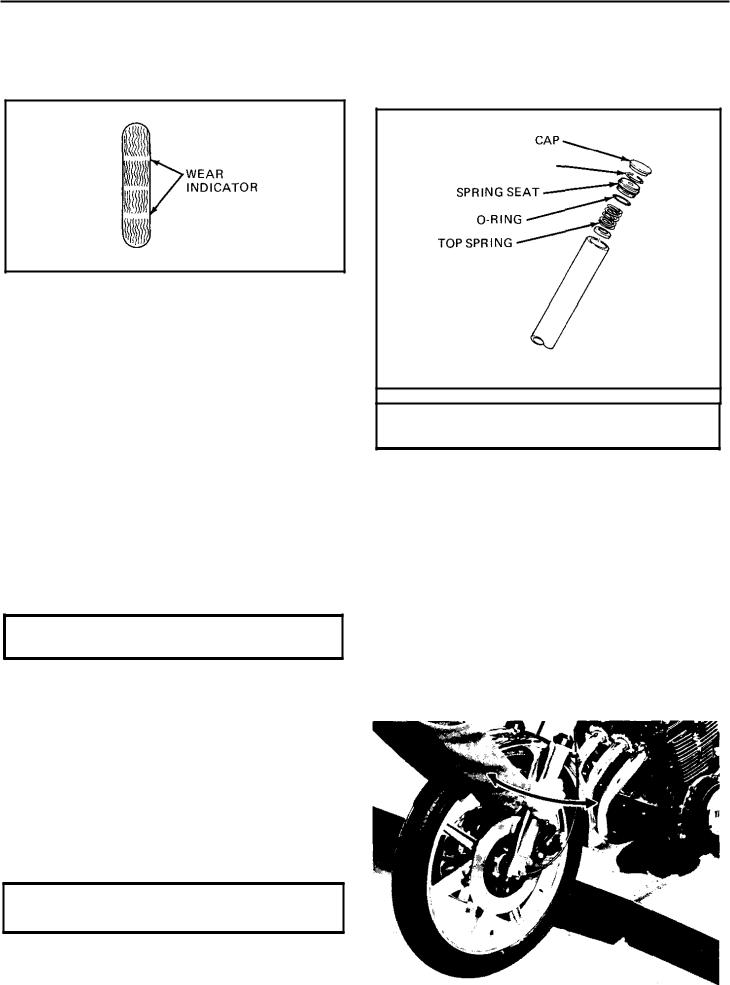
b. Check the tire wear
If a tire tread shows crosswise lines, it means that the tire is worn to it s limit. Replace the tire.
9.Inspect the O-ring on the spring seat. Replace O-ring if damaged.
10.Reinstall top spring, O-ring, spring seat, stopper ring and rubber cap.
E.Front Fork Oil Change
1.Raise the machine or remove the front wheel so that there is no weight on the front end of the machine.
2.Remove the rubber cap from the top of each fork.
3.The spring seat and springs are retained by a stopper ring (spring wire circlip). It is necessary to depress the spring seat and fork springs to remove the stopper ring. Remove the stopper ring by carefully prying out one end with a small screwdriver.
4.Place open container under each drain hole. Remove drain screw from each outer tube.
CAUTION: Do not allow oil to contact disc brake components.
5.When most of the oil has drained, slowly raise and lower the outer tubes to pump the remaining oil. It may be necessary to
remove the spring seat and top spring to keep them from falling out when raising fork tubes.
6.Inspectdrain screw gasket. Replace ifdamaged. Reinstall drain screw.
7.Pour specified amount of oil into the fork inner tube.
Front fork oil (each fork): 170cc 2OW Yamaha Fork Oil
8.After filling, slowly pump the outer tubes up and down to distribute the oil.
STOPPER RING
CAUTION: Always use a new stopper ring (wire circlip).
F. Steering Head Adjustment
The XS750D steering head is fitted with tapered roller bearings. The steering assembly should be checked periodically for looseness.
Procedure
1.Raise front end of machine so that there is no weight on the front wheel.
2.Grasp bottom of forks and gently rock fork assembly backward and forward, checking for looseness in the steering assembly bearings.
3.If there is looseness inthe steering head, loosen the crown pinch bolt and steering fitting bolt.
4.Use steering nut wrench to loosen top steering fitting nut. The top nut serves as a lock nut.
5.Tighten the lower steering fitting nut until the steering head is tight, but does not bind when forks are turned.
6.Retighten the top steering fitting nut, steering fitting bolt and crown pinch bolt, inthat order.
7.Recheck steering adjustment to make sure there is no binding when the forks are moved from lock to lock. If necessary, repeat adjustment procedure.
G.Throttle Cable And Grip Lubrication
The throttle twist grip assembly should be greased a t the time that the cable is lubricated since the grip must be removed to get a t the end of the throttle cable. Two screws clamp the throttle housing to the handlebar. Once these two are removed, the end of the cable can be heid high to pour in several drops of lubricant. With the throttle grip disassembled, coat the inside surface of the throttle grip guide tube with
asuitable all-purpose grease to cut down friction.
H. Lubrication Of Levers, Pedals, Etc.
1.Lubricate the pivoting parts of the brake and clutch levers with motor oil (10W30).
2.Lubricate the shaft of the brake pedal with lithium soap grease.
2-5 ELECTRICAL
A.Contact Breaker Point Adjustment
1.Remove breaker point cover.
2.Each cylinder has a set of breaker points. The No. 1 (left) cylinder set is marked with a "1" on the backing plate. The No. 2 (center) cylinder set is marked with a "2", and the No. 3 cylinder set is marked "3". The spark plug wires are also numbered.
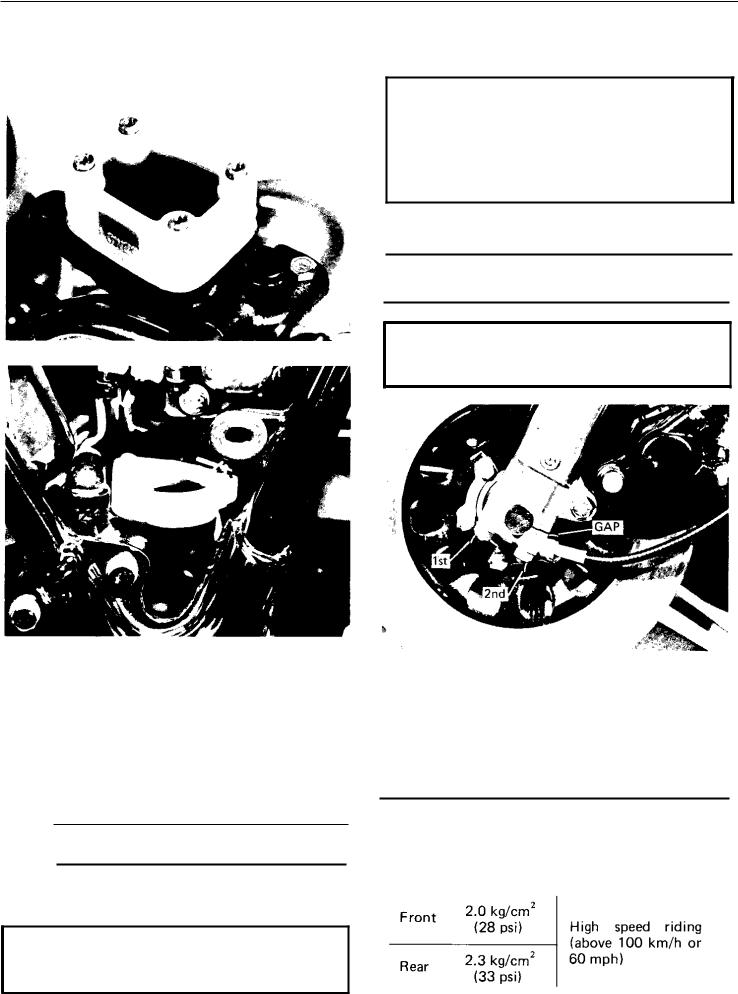
3.Check contact breaker point gap (at largest gap) with feeler gauge.
Contact Breaker Gap:
0.3 - 0.4mm (.012~.016 in.)
If necessary, adjust by loosening securing screws and moving the adjustable contact point.
4.Tighten adjusting screws and recheck breaker point gap.
B.Contact Breaker Point Maintenance
1.Apply a few drops of lightweight lubricant to the point cam lubricators.
2.The points can be lightly sanded with fine emery paper to remove corrosion. Then place a piece of clean paper between the points and let them close. Remove the paper. Repeat until no residue shows. The paper may be dipped in lacquer thinner or contact point cleaning fluid to remove oil or sanding residue from the point surface.
3.Point replacement should be necessary only when point gap exceeds maximum tolerance, when the points become severely pitted, or if the points become shorted or show faulty operation. New points must be cleaned and adjusted when installed.
C.Ignition Timing
NOTE: Point gap must beset before setting timing.
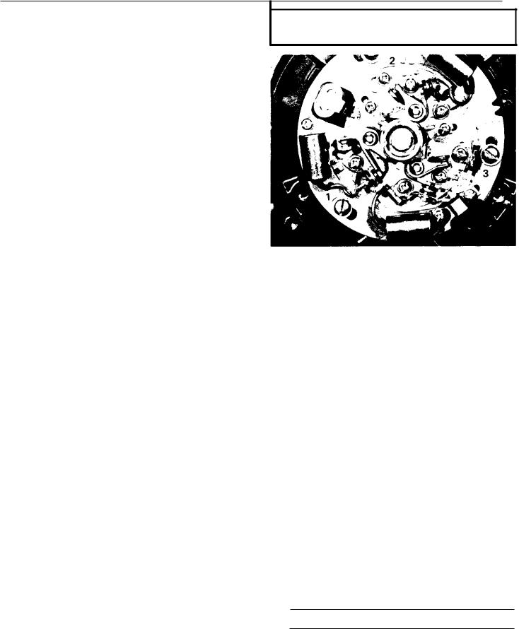
1.Ignition timing is checked with a timing light by observing the position of the stationary pointer and the marks stamped on the governor assembly. The governor assembly is marked as follows:
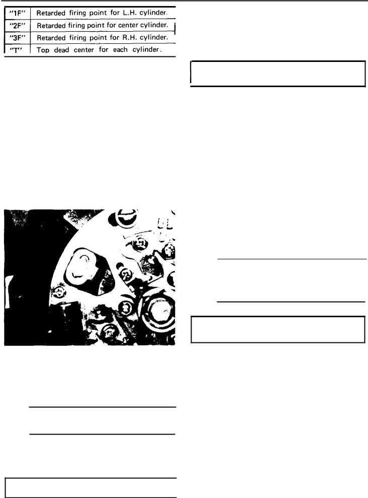
There are also three (3) pair of unmarked lines. They indicate the Full Advance firing range for each cylinder.
Connect timing light to No. 1 (left) cylinder.
2.Ignition timing of No. 1 cylinder must be set first. Connect timing light to No. 1 spark plug lead wire.
3.Start engine
4.The stationary pointer should line up with the " 1F " timing mark on the governor. If it does not align, loosen 3 breaker backing plate screws and move the complete backing plate until "1F" and the pointer marks align.
8.The above procedure is recommended for set- ting ignition timing. However, the following information is provided so that the position of the static pointer can be verified using a degree wheel.
Retarded ignition: 10° BTDC
Fully Advanced Ignition: 38.5±1.5° BTDC
D. Battery
A poorly maintained battery will deteriorate quickly. The battery fluid should be checked a t least once a month.
1.The level should be between the upper and lower level marks. Use only distilled water for refilling. Normal tap water contains minerals which are harmful to a battery; therefore, re- fill only with distilled water.
2.Always make sure the connections are correct when installing the battery. The red lead i s for the (+) terminal and the black lead is for the (-) terminal. Make sure the breather pipe is properly connected, properly routed, and is not damaged or obstructed.
NOTE: The battery must be charged before using to insure maximum performance. Failure
to properly charge the battery before first use, or a low electrolyte level, will cause premature failure of the battery.
5.Retighten screw. Check timing again for the No. 1 cylinder.
6.Rev the engineto above 3,000 rpm. The pointer should indicate the area of the two "full advance" marks on the governor.
NOTE: Retarded ignition: 1,100~1,550 Advance begins: 1,600'
Full Advance achieved: 2,900
7.Repeat procedure (steps 2-7) for remaining cylinders. Loosen each individual point assembly plate before adjusting. Retighten screws and recheck timing for each cylinder.
CAUTION: Never bend adjusting pointer.
Charging current: 1.4 Amps
Charging hours: 10 hrs.
E. Spark Plug
The spark plug indicates how the engine is operating. If the engine is operating correctly. and the machine is being ridden properly, the tip of the white insulator around the positive electrode of the spark plug will be a medium tan color. If the insulator is very dark brown or black color, then a plug with a hotter heat range might be required. This situation is quite common during the engine break-in period. If the insulator tip shows a very light tan or white color or is actually pure white and glazed, or if electrodes show signs of melting, then a spark plug with a colder heat range is required. Remember, the insulator area surrounding the positive electrode of the spark plug must be a medium tan color. If it is not, check carburetion, timing and ignition adjustments.
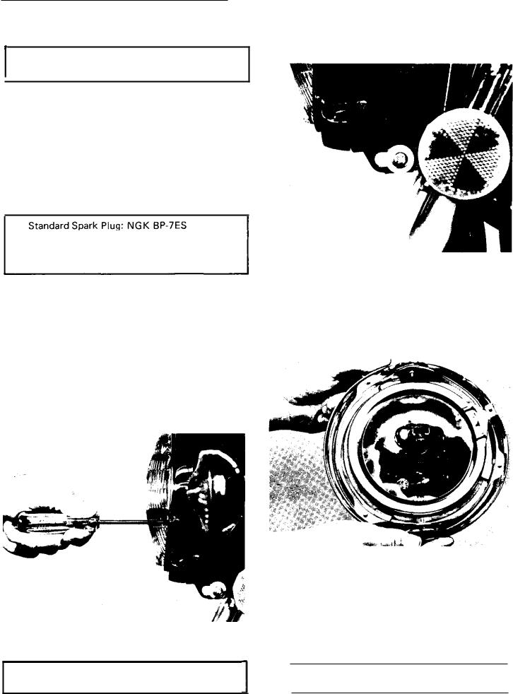
The spark plug must be removed and checked. Check electrode wear, insulator color, and electrode gap.
Spark plug gap:
0.6~0.7mm (0.02~0.03 in.)
Engine heat and combustion chamber deposits will cause any spark plug to slowly break down and erode. If the electrodes finally become too worn, or if for any reason you believe the spark plug is not functioning correctly, replace it. When installing the plug, always clean the gasket surface, use a new gasket, wipe off any grime that might be present on the surface of the spark plug, and torque the spark plug properly.
Champion N - 7 Y
Tightening Torque: 1.5~2.5 m-kg
(10.8~18.1 ft-lb)
F.Headlight
1.Headlight beam adjustment.
When necessary, adjust the headlight beam as follows:
a.Adjust horizontally by tightening or loosening the adjust screw.
To adjust to the right: Tighten the screw To adjust to the left: Loosen the screw
b.Adjust vertically as follows:
1)Loosen adjusting screw under headlight body.
Adjust vertically by moving the headlight body. When proper adjustment is determined, retighten adjusting screw.
2.Replacing the headlight bulb.
a.Unhook springs and pull the defective unit out of the shell.
b.Slip a new unit into position and install springs.
c.Adjust headlight beam.
NOTE: Take care not to damage the headlight. It is very fragile.
ENGINE OVERHAUL
3 - 1 ENGINE REMOVAL
NOTE: It is not necessary t o remove the engine to remove the cylinder head, cylinder, or pistons.
A. Preparation For Removal
the "on" position unless the engine is operating). Disconnect fuel pipes and vacuum pipes from petcock.
2.Lift seat and remove fuel tank holding bolt. Remove fuel tank.
1.All dirt, mud, dust and foreign material should be thoroughly removed from the exterior of the engine before removal and disassembly. This will help prevent any harmful foreign material from entering the engine.
2.Before engine removal and disassembly, be sure that you have the proper tools and cleaning equipment so that you can perform a clean and efficient job.
3.During disassembly of the engine, clean and place all parts in trays in order of disassembly.
This will speed assembly time and help insure correct reinstallation o f all engine parts.
4. Place machine on center stand. Start engine |
|
|
|
|
|
|
|
|
|
|
|
|
|
|
and allow it t o warm up. Stop engine and |
C. |
Muffler, Footrest, Brake Pedal |
||||||||||
|
drain engine/transmission oil. |
||||||||||||
|
|
|
|
|
|
|
|
|
|
|
|
|
|
5. |
Remove oil filter element t o drain oil filter. |
|
|
|
|
Remove rear brake pedal and passenger right |
|||||||
|
|
|
|
|
|
footrest. |
|||||||
6. |
If middle gear case is t o be removed, drain |
|
2. Remove exhaust pipe holding screws from cy- |
||||||||||
|
middle gear oil. |
|
|||||||||||
|
|
|
|
|
|
linder head. |
|||||||
7. |
Remove air scoop from cylinder head cover. |
|
|
|
|
|
|
|
|
|
|
|
|
|
|
|
|
|
|
|
|
|
|
|
|
|
|
|
|
|
|
|
|
|
|
|
|
|
|
|
|
|
|
|
|
|
|
|
|
|
|
|
|
|
|
|
|
|
|
|
|
|
|
|
|
|
|
|
|
|
|
|
|
|
|
|
|
|
|
|
|
|
|
|
|
|
|
|
|
|
|
|
|
|
|
|
|
|
|
|
|
|
|
|
|
|
|
|
|
|
|
|
|
|
|
|
|
|
|
|
|
|
|
|
|
|
|
|
|
|
|
|
|
|
|
|
|
|
|
|
|
|
|
|
|
|
|
|
|
|
|
|
|
|
|
|
|
|
|
|
|
|
|
|
|
|
|
|
|
|
|
|
|
|
|
|
|
|
|
|
|
|
|
|
|
|
|
|
|
|
|
|
|
|
|
|
|
|
|
|
|
|
|
|
|
|
|
|
|
|
|
|
|
|
|
|
|
|
|
|
|
|
|
|
|
|
|
|
|
|
|
|
|
|
|
|
|
|
|
|
|
|
|
|
|
|
|
|
|
|
|
|
|
|
|
|
|
|
|
|
|
|
|
|
|
|
|
|
|
|
|
|
|
|
|
|
|
|
|
|
|
|
|
|
|
|
|
|
|
|
|
|
|
|
|
|
|
|
|
|
|
|
|
|
|
|
|
|
|
|
|
|
|
|
|
|
|
|
|
|
|
|
|
|
|
|
|
|
|
|
|
|
|
|
|
|
|
|
|
|
|
|
|
|
|
|
|
|
|
|
|
|
|
|
|
|
|
|
|
|
|
|
|
|
|
|
|
|
|
|
|
|
|
|
|
|
|
|
|
|
|
|
|
|
|
|
|
|
|
|
|
|
|
|
|
|
|
|
|
|
|
|
|
|
|
|
|
|
|
|
|
|
|
|
|
|
|
|
|
B. Fuel Tank Removal |
|
1. Turn fuel petcocks t o "on" (there is no "off" |
3. Remove exhaust pipes and muffler as an |
position-fuel will not flow from a petcock on |
assembly. |

D. Side Cover, Air Cleaner Case |
4. Remove bolts holding air cleaner case to |
1. Remove left and right side covers. |
frame. Note ground wire connection on left |
frame bracket. |
|
|
|
|
|
|
|
|
|
|
|
|
|
|
|
|
|
|
|
|
|
|
|
|
|
DOHC 
5. Pull air cleaner case t o the rear. Remove clutch cable from holder attached t o the left carburetor. Lift carburetors back and to the left. Remove throttle cable from carburetors.
2.Remove screws holding intake silencers (left and right). Remove intake silencers.
3.Loosen clamps holdingcarburetors t o air cleaner case and intake manifolds. Loosen breather hose clamp a t air cleaner case junction.
6.Remove air cleaner case,
E.Wiring and Cables
1.Pull back rubber cover on clutch adjustor a t engine. Disconnect clutch cable.
2.Remove spark plugwires and tachometer cable.
3.Remove two ( 2 ) screws holding starter motor cover. Remove starter motor cover. Disconnect electric starter cable.
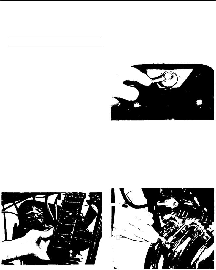
F.Drive Shaft Joint
1.Pull rubber boot from drive shaft coupling t o expose four (4) bolts.
2. Remove four (4) bolts on drive shaft coupling.
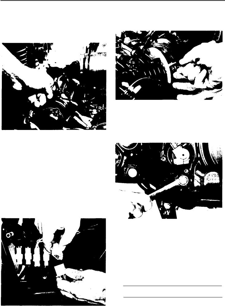
G. Removal
1. Remove three (3)engine mounting bolts from frame. Remove footrests with the two (2 ) rear engine mounting bolts.
4.Disconnect ground wire from top of engine case.
5.Disconnect wiring harness couplers on left side of machine. Remove ignition wiring (orange, yellow, grey, blue wires), generator wiring (white wires), and field wiring (green, black wires). Position wires so that they can be safe- ly removed.
2. Slide engine forward. Remove engine t o the right. Position a box or other support to the right of the machine for assistance when removing the engine.
3-2 ENGINE DISASSEMBLY
A. Cylinder Head and Cylinder Removal
NOTE: Cylinder head and cylinder can be removed without removing engine.
1. Remove cylinder head cover.
 Loading...