


Yamaha
XV535
through 1100
Owners
Workshop
Manual
by Alan Ahlstrand and John H Haynes
Member of the Guild of Motoring Writers
Models covered:
USA: Yamaha XV535 Virago. 535cc. 1987 through 1990 and 1993 through 1994
Yamaha XV535S Virago. 535cc. 1994
Yamaha XV700 Virago. 699cc. 1984 through 1987 Yamaha XV750 Virago. 748cc. 1981 through 1983 and
1988 through 1994
Yamaha XV920 Virago. 920cc. 1982 and 1983 Yamaha XV920R (chain drive). 920cc. 1981 and 1982 Yamaha XV1000 Virago. 981 cc. 1984 and 1985 Yamaha XV1100 Virago. 1063cc. 1986 through 1994
UK: Yamaha XV535. 535cc. 1988 through 1994 Yamaha XV535S. 535cc. 1994
Yamaha XV750SE Special. 748cc. 1981 through 1983 Yamaha XV750 Virago. 748cc. 1992 through 1994 Yamaha TR1 (chain drive). 981cc. 1981 through 1985 Yamaha XV1000 Virago. 981 cc. 1986 through 1989 Yamaha XV1100 Virago. 1063 cc. 1989 through 1994
ABCDE
FGHIJ
KLMNO
PQRS
Haynes Publishing
Sparkford Nr Yeovil
Somerset BA22 7JJ England
Haynes North America, Inc
861 Lawrence Drive
Newbury Park
California 91320 USA .
Acknowledgements
Our thanks to Mitsui Machinery Sales (UK) Ltd for permission to reproduce certain illustrations used in this manual. We would also like to thank NGK Spark Plugs (UK) Ltd for supplying the color spark plug condition photos and the Avon Rubber Company for supplying information on tire fitting. Special thanks to Grand Prix Kawasaki/Yamaha, Santa Clara, California, for providing the facilities used for these photographs; to Mark Woodward, service manager, for arranging the facilities and fitting the mechanical work into his shop's busy schedule; and to Denny Jewell, service technician, for doing the mechanical work and providing valuable technical information,
© Haynes North America, Inc. 1994
With permission from J.H. Haynes & Co. Ltd.
A book in the Haynes Owners Workshop Manual Series
Printed in the U.S.A.
All rights reserved. No part of this book may be reproduced or transmitted in any form or by any means, electronic or mechanical, including photocopying, recording or by any information storage or retrieval system, without permission in writing from the copyright holder.
ISBN1 56392103 0
Library of Congress Catalog Card Number 94-73120
British Library Cataloguing in Publication Data
A catalogue record for this book is available from the British Library
We take great pride in the accuracy of information given in this manual, but motorcycle manufacturers make alterations and design changes during the production run of a particular motorcycle of which they do not inform us. No liability can be accepted by the authors or publishers for loss, damage or injury caused by any errors in, or omissions from, the information given.
94-360
Contents
Introductory pages |
|
About this manual |
0-6 |
Introduction to the Yamaha XV |
0-6 |
Identification numbers |
0-7 |
Buying parts |
0-8 |
General specifications |
0-8 |
Maintenance techniques, tools and working facilities |
0-11 |
Safety first! |
0-17 |
Motorcycle chemicals and lubricants |
0-18 |
Troubleshooting |
0-19 |
Chapter 1 |
|
Tune-up and routine maintenance |
1-1 |
Chapter 2 Part A |
|
Engine, clutch and transmission (XV535 models) |
2A-1 |
Chapter 2 Part B |
|
Engine, clutch and transmission (XV700 through 1100 models) |
2B-1 |
Chapter 3 Part A |
|
Fuel and exhaust systems (XV535 models) |
3A-1 |
Chapter 3 Part B |
|
Fuel and exhaust systems (XV700 through 1100 models) |
3B-1 |
Chapter 4 Part A |
|
Ignition system (XV535 models) |
4A-1 |
Chapter 4 Part B |
|
Ignition system (XV700 through 1100 models) |
4B-1 |
Chapter 5 Part A |
|
Steering, suspension and final drive (XV535 models) |
5A-1 |
Chapter 5 Part B |
|
Steering, suspension and final drive (XV700 through 1100 models) |
5B-1 |
Chapter 6 Part A |
|
Brakes, wheels and tires (XV535 models) |
6A-1 |
Chapter 6 Part B |
|
Brakes, wheels and tires (XV700 through 1100 models) |
6B-1 |
Chapter 7 Part A |
|
Frame and bodywork (XV535 models) |
7A-1 |
Chapter 7 Part B |
|
Frame and bodywork (XV700 through 1100 models) |
7B-1 |
Chapter 8 Part A |
|
Electrical system (XV535 models) |
8A-1 |
Chapter 8 Part B |
|
Electrical system (XV700 through 1100 models) |
8B-1 |
Chapter 9 |
|
Wiring diagrams |
9-1 |
Conversion factors
Index |
IND-1 |
0-4 |
Yamaha XV |
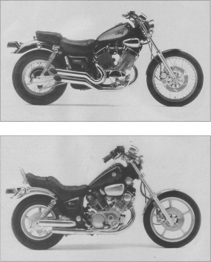
The 1994 XV535S model
The 1985 XV700 Virago model

Yamaha XV |
0-5 |
The TR1 model
The 1994 XV1100 Virago model
0-6
About this manual
Its purpose
The purpose of this manual is to help you get the best value from your motorcycle. It can do so in several ways. It can help you decide what work must be done, even if you choose to have it done by a dealer service department or a repair shop; it provides information and procedures for routine maintenance and servicing; and it offers diagnostic and repair procedures to follow when trouble occurs.
We hope you use the manual to tackle the work yourself. For many simpler jobs, doing it yourself may be quicker than arranging an appointment to get the vehicle into a shop and making the trips to leave it and pick it up. More importantly, a lot of money can be saved by avoiding the expense the shop must pass on to you to cover its labor and overhead costs. An added benefit is the sense of satisfaction and accomplishment that you feel after doing the job yourself.
Using the manual
The manual is divided into Chapters. Each Chapter is divided into numbered Sections, which are headed in bold type between horizontal lines. Each Section consists of consecutively numbered paragraphs.
At the beginning of each numbered Section you will be referred to any illustrations which apply to the procedures in that Section. The reference numbers used in illustration captions pinpoint the pertinent
Section and the Step within that Section. That is, illustration 3.2 means the illustration refers to Section 3 and Step (or paragraph) 2 within that
Section.
Procedures, once described in the text, are not normally repeated. When it's necessary to refer to another Chapter, the reference will be given as Chapter and Section number. Cross references given without use of the word "Chapter" apply to Sections and/or paragraphs in the same Chapter. For example, "see Section 8" means in the same Chapter.
References to the left or right side of the vehicle assume you are sitting on the seat, facing forward.
Motorcycle manufacturers continually make changes to specifications and recommendations, and these, when notified, are incorporated into our manuals at the earliest opportunity.
Even though we have prepared this manual with extreme care, neither the publisher nor the author can accept responsibility for any errors in, or omissions from, the information given.
NOTE
A Note provides information necessary to properly complete a procedure or information which will make the procedure easier to understand.
CAUTION
A Caution provides a special procedure or special steps which must be taken while completing the procedure where the Caution is found. Not heeding a Caution can result in damage to the assembly being worked on.
WARNING
A Warning provides a special procedure or special steps which must be taken while completing the procedure where the Warning is found. Not heeding a Warning can result in personal injury.
Introduction to the Yamaha XV
The Yamaha XV (Virago) series are highly successful and popular cruiser-style motorcycles.
The engine on all models is an air-cooled, V-twin with overhead camshafts. .
Fuel is delivered to the cylinders by two Hitachi or Mikuni carburetors; XV535, XV1000 and XV1100 models use an electric fuel pump.
The front suspension uses a pair of conventional forks, adjustable by varying the fork air pressure on some models. Fork damping is adjustable on XV920 J models.
The rear suspension on 1981 through 1983 models uses a single shock absorber and coil spring. Later models use twin rear shock absorbers with concentric coil springs. Spring preload is adjustable on all XV700 through 1100 models; shock absorber damping is adjustable on 1984 and later XV700 through 1100 models.
The front brake uses a single or dual disc; a drum brake is used at the rear.
Shaft final drive is used on most of the bikes covered in this manual. Some models use an unusual chain drive system, with the chain completely enclosed in housings and running in a bath of grease.
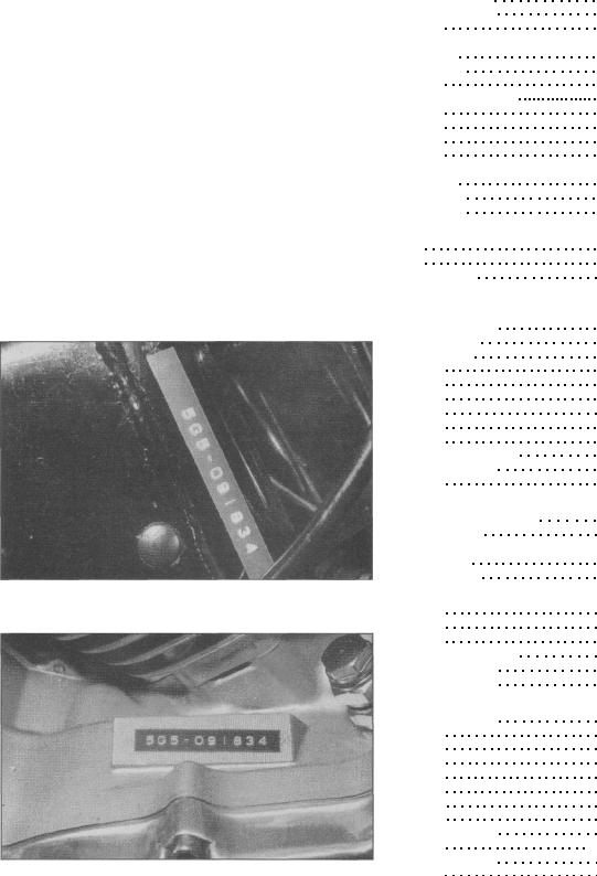
Identification numbers
The frame serial number is stamped into the right side of the frame and printed on a label affixed to the frame. The engine number is stamped into the right upper side of the crankcase. Both of these numbers should be recorded and kept in a safe place so they can be furnished to law enforcement officials in the event of a theft.
The frame serial number, engine serial number and carburetor identification number should also be kept in a handy place (such as with your driver's license) so they are always available when purchasing or ordering parts for your machine.
The models covered by this manual are as follows: XV535, 1987 through 1990 US
XV535, 1993 and 1994 US XV535, 1988 through 1994 UK
XV700,1984 through 1987 US
XV750, 1981 through 1983 and 1988 through 1994 US
XV750, 1981 through 1983 UK, 1992 through 1994 UK XV920, 1981 through 1983 US
XV1000 shaft drive, 1984 and 1985 US,
1986 through 1989 UK
XV1000 chain drive (TR1), 1981 through 1985 UK XV1100, 1986 through 1994 US, 1989 through 1994 UK
Identifying engines and model years
The procedures in this manual identify the bikes by model year. To determine which model year a given machine is, look for the following identification codes in the engine and frame numbers:
The frame number is stamped in the right side of the frame and is also displayed on a decal
The engine number is stamped in the right side of the crankcase
0-7
Year |
|
Code |
XV535 models |
|
|
1987and 1988 US |
|
2GV |
1989 and 1990 US |
|
3JC1/3JC2 |
1993 US |
|
3JC7/3JC8 |
1994 US |
|
|
XV535 |
|
3JCA, 3JCB |
XV535S |
|
3JCB, 3JCD |
1988 UK |
|
3BT1 |
1989 |
UK. |
3BT2/3BT5 |
1990 UK |
|
3BTC/3BT8 |
1991 UK |
|
3BTE/3BTF |
1992 UK |
|
3BTK/3BTM |
1993 UK |
|
3BTR/3BTT |
1994 UK |
|
|
XV535 |
|
4KU2/3BTW |
XV535S |
|
4KU4 (flat handlebar) |
XV535S |
|
3BTV/3BTY (upright handlebar) |
XV700 models |
|
|
1984 |
|
42W/42X |
1985 |
|
56E/56F |
1986 and 1987 |
|
1RM/1RV/1RR/1TU |
XV750 models |
|
|
1981 through 1983 US |
|
|
XV750 H, J, K |
|
4X7 |
XV750 MK |
|
20X |
1988 U S . . |
|
3AL/3CM |
1989 US |
|
3JL1/3JL2 |
1990 US |
|
3JL4/3JL5 |
1991 US |
|
3JL7/3JL8 |
1992 US |
|
3JUV3JLB |
1993 US |
|
3JLD/3JLE |
1994 US |
|
3JLG/3JLH |
1981 through 1983 UK |
5G5 |
|
1992 and 1993 UK |
|
4FY1 |
1994 UK |
|
4FY4 |
XV920 models |
|
|
1981 and 1982 chain drive |
5H1 |
|
1982 shaft drive |
|
10L |
1983 shaft drive |
|
|
XV920 K |
|
24M |
XV920 MK |
|
27Y |
XV1000 models |
|
|
1984 US |
|
42G/42H |
1985 US |
|
56V/56W |
1981 UK |
|
5A8 |
1982 through 1985 UK |
19T |
|
1986 and 1987 UK |
|
2AE |
1988 and 1989 UK |
|
3DR1 |
XV1100 models |
|
|
1986 and 1987 US |
|
1TE/1TA |
1988 US |
|
3CF/3CG |
1989 US |
|
3JK1/3JK2 |
1990 US |
|
3JK4/3JK5 |
1991 US |
|
3JK7/3JK8 |
1992 US |
|
3JKB/3JKC |
1993 US |
|
3JKA/3JKE |
1994 US |
|
3JKG/3JKH |
1989 and 1990 UK |
|
3LP1 |
1991 UK |
|
. 3LP2 |
1992 and 1993 UK |
3LP4 |
|
1994 UK |
|
3LP8 |

0-8
Buying parts
Once you have found all the identification numbers, record them for reference when buying parts. Since the manufacturers change specifications, parts and vendors (companies that manufacture various components on the machine), providing the ID numbers is the only way to be reasonably sure that you are buying the correct parts.
Whenever possible, take the worn part to the dealer so direct comparison with the new component can be made. Along the trail from the manufacturer to the parts shelf, there are numerous places that the part can end up with the wrong number or be listed incorrectly.
The two places to purchase new parts for your motorcycle - the accessory store and the franchised dealer - differ in the type of parts they carry. While dealers can obtain virtually every part for your
motorcycle, the accessory dealer is usually limited to normal high wear items such as shock absorbers, tune-up parts, various engine gaskets, cables, chains, brake parts, etc. Rarely will an accessory outlet have major suspension components, cylinders, transmission gears, or cases.
Used parts can be obtained for roughly half the price of new ones, but you can't always be sure of what you're getting. Once again, take your worn part to the wrecking yard (breaker) for direct comparison.
Whether buying new, used or rebuilt parts, the best course is to deal directly with someone who specializes in parts for your particular make.
General specifications
XV535 models
1987 and 1988 US models
Wheelbase |
1511 mm (59.5 inches) |
Overall length |
2210 mm (87.0 inches) |
Overall width |
815 mm (32.1 inches) |
Overall height |
1100 mm (43.3 inches) |
Seat height |
700 mm (27.6 inches) |
Ground clearance (minimum) |
145 mm (5.7 inches) |
Weight (with oil and full fuel tank) |
|
US except California |
185 kg (408 lbs) |
California |
186 kg (410 lbs) |
1989-on US models
Wheelbase |
1520 mm (59.8 inches) |
Overall length |
2225 mm (87.6 inches) |
Overall width |
810 mm (31.9 inches) |
Overall height |
1110 mm (43.7 inches) |
Seat height |
720 mm (28.3 inches) |
Ground clearance (minimum) |
160 mm (6.3 inches) |
Weight (with oil and full fuel tank) |
|
US except California |
195 kg (430 lbs) |
California |
196 kg (432 lbs) |
1988 UK models
Wheelbase |
. |
1520 mm (59.8 inches) |
Overall length |
|
2225 mm (87.6 inches) |
Overall width |
|
810 mm (31.9 inches) |
Overall height |
|
1100 mm (43.3 inches) |
Seat height |
|
700 mm (27.6 inches) |
Ground clearance (minimum) |
|
160 mm (6.3 inches) |
Weight (with oil and full fuel tank) |
|
188 kg (415 lbs) |

|
|
General specifications |
0-9 |
1989-on UK models |
|
|
|
Wheelbase |
|
1520 mm (59.8 inches) |
|
Overall length |
|
2285 mm (90.0 inches) |
|
Overall width |
|
|
|
Flat handlebar |
|
725 mm (88.6 inches) |
|
Upright handlebar |
|
810 mm (31.9 inches) |
|
Overall height |
|
|
|
Flat handlebar |
|
1070 mm (42.1 inches) |
|
Upright handlebar |
|
1110 mm (43.7 inches) |
|
Seat height |
|
720 mm (28.3 inches) |
|
Ground clearance (minimum) |
|
160 mm (6.3 inches) |
|
Weight (with oil and full fuel tank) |
|
195 kg (430 lbs) |
|
XV700 and US XV1000 models |
|
|
|
Wheelbase |
|
1525 mm (60.0 inches) |
|
Overall length |
|
2235 mm (88.0 inches) |
|
Overall width |
|
840 mm (33.1 inches) |
|
Overall height |
|
1170 mm (46.1 inches) |
|
Seat height |
|
715 mm (28.1 inches) |
|
Ground clearance (minimum) |
|
145 mm (5.7 inches) |
|
Weight (with oil and full fuel tank) |
|
|
|
1984 and 1985 XV700 models |
|
225 kg (496 lbs) |
|
1986 and 1987 XV700 models |
|
229 kg (505 lbs) |
|
XV1000 models |
|
236 kg (520 lbs) |
|
XV750 models (1981 through 1983) |
|
|
|
Wheelbase |
|
1520 mm (59.8 inches) |
|
Overall length |
|
2230 mm (87.8 inches) |
|
Overall width |
|
|
|
US models |
|
805 mm (31,7 inches) |
|
UK models |
|
840 mm (33.1 inches) |
|
Overall height |
|
|
|
US models |
|
1160 mm (45.7 inches) |
|
UK models |
|
1210 mm (47.6 inches) |
|
Seat height.... |
|
not specified |
|
Ground clearance (minimum) |
|
145 mm (5.7 inches) |
|
Weight (dry) |
|
|
|
US models |
|
225 kg (496 lbs) |
|
UK models |
. |
211 kg (465 lbs) |
|
XV750 models (1988-on US) |
|
|
|
Wtieelbase |
|
1525 mm (60.0 inches) |
|
Overall length |
|
2285 mm (90.0 inches) |
|
Overall width |
|
840 mm (33.1 inches) |
|
Overall height |
|
1190 mm (46.9 inches) |
|
Seat height |
|
715 mm (28.1 inches) |
|
Ground clearance (minimum) |
|
145 mm (5.7 inches) |
|
Weight |
|
Not specified |
|
XV750 models (1992-on UK) |
|
|
|
Wheelbase |
|
1525 mm (60.0 inches) |
|
Overall length |
|
2285 mm (90.0 inches) |
|
Overall width |
|
840 mm (33.1 inches) |
|
Overall height.. |
|
1190 mm (46.9 inches) |
|
Seat height |
|
715 mm (28.1 inches) |
|
Ground clearance (minimum) |
|
145 mm (5.7 inches) |
|
Weight |
|
|
|
1992 and 1993 models |
|
235 kg (518 lbs) |
|
1994 models |
|
236 kg (520 lbs) |
|
XV920 J models |
|
|
|
Wheelbase |
|
1520 mm (59.8 inches) |
|
Overall length |
|
2220 mm (87.4 inches) |
|
Overall width |
. |
840 mm (33.1 inches) |
|
Overall height |
|
1205 mm (47.4 inches) |
|
Seat height |
|
Not specified |
|
Ground clearance (minimum) |
. |
145 mm (5.7 inches) |
|
Weight |
|
225 kg (496 lbs) |
|
0-10 |
General specifications |
XV920 K and MK models |
|
Wheelbase |
1520 mm (59.8 inches) |
Overall length |
2230 mm (87.8 inches) |
Overall width |
805 mm (31.7 inches) |
Overall height |
1160 mm (45.7 inches) |
Seat height |
Not specified |
Ground clearance (minimum) |
145 mm (5.7 inches) |
Weight |
235 kg (518 lbs) |
XV920 RH and RJ models |
|
Wheelbase |
1540 mm (60.6 inches) |
Overall length |
2260 mm (89.0 inches) |
Overall width |
930 mm (36.6 inches) |
Overall height |
1170 mm (46.1 inches) |
Seat height |
Not specified |
Ground clearance (minimum) |
140 mm (5.5 inches) |
Weight |
224 kg (493 lbs) |
XV1000 models (1981 through 1985 UK TR1) |
|
Wheelbase |
1540 mm (60.6 inches) |
Overall length |
2265 mm (89.2 inches) |
Overall width |
730 mm (28.7 inches) |
Overall height |
1170 mm (46.1 inches) |
Seat height |
Not specified |
Ground clearance (minimum) |
140 mm (5.5 inches) |
Weight |
220 kg (485 lbs) |
XV1100 models (1986-on) |
|
Wheelbase |
1525 mm (60.0 inches) |
Overall length |
|
US models |
2235 mm (88.0 inches) • |
UK models |
2285 mm (90.0 inches) |
Overall width |
840 mm (33.1 inches) |
Overall height |
|
1986 and 1987 |
1170 mm (46.1 inches) |
1988-on |
1190 mm (46.9 inches) |
Seat height |
715 mm (28.1 inches) |
Ground clearance (minimum) |
145 mm (5.7 inches) |
Weight (with oil and full fuel tank) |
|
US models |
239 kg (527 lbs) |
UK models |
240 kg (529 lbs) |
0-11
Maintenance techniques, tools and working facilities
Basic maintenance techniques
There are a number of techniques involved in maintenance and repair that will be referred to throughout this manual. Application of these techniques will enable the amateur mechanic to be more efficient, better organized and capable of performing the various tasks properly, which will ensure that the repair job is thorough and complete.
Fastening systems
Fasteners, basically, are nuts, bolts and screws used to hold two or more parts together. There are a few things to keep in mind when working with fasteners. Almost all of them use a locking device of some type (either a lock washer, locknut, locking tab or thread adhesive). All threaded fasteners should be clean, straight, have undamaged threads and undamaged corners on the hex head where the wrench fits. Develop the habit of replacing all damaged nuts and bolts with new ones.
Rusted nuts and bolts should be treated with a penetrating oil to ease removal and prevent breakage. Some mechanics use turpentine in a spout type oil can, which works quite well. After applying the rust penetrant, let it "work" for a few minutes before trying to loosen the nut or bolt. Badly rusted fasteners may have to be chiseled off or removed with a special nut breaker, available at tool stores.
If a bolt or stud breaks off in an assembly, it can be drilled out and removed with a special tool called an E-Z out (or screw extractor). Most dealer service departments and motorcycle repair shops can perform this task, as well as others (such as the repair of threaded holes that have been stripped out).
Flat washers and lock washers, when removed from an assembly, should always be replaced exactly as removed. Replace any damaged washers with new ones. Always use a flat washer between a lock washer and any soft metal surface (such as aluminum), thin sheet metal or plastic. Special locknuts can only be used once or twice before they lose their locking ability and must be replaced.
Tightening sequences and procedures
When threaded fasteners are tightened, they are often tightened to a specific torque value (torque is basically a twisting force). Overtightening the fastener can weaken it and cause it to break, while under-tightening can cause it to eventually come loose. Each bolt, depending on the material it's made of, the diameter of its shank and the material it is threaded into, has a specific torque value, which is noted in the Specifications. Be sure to follow the torque recommendations closely.
Fasteners laid out in a pattern (i.e. cylinder head bolts, engine case bolts, etc.) must be loosened or tightened in a sequence to avoid warping the component. Initially, the bolts/nuts should go on finger tight only. Next, they should be tightened one full turn each, in a crisscross or diagonal pattern. After each one has been tightened one full turn, return to the first one tightened and tighten them all one half turn, following the same pattern. Finally, tighten each of them one quarter turn at a time until each fastener has been tightened to the proper torque. To loosen and remove the fasteners the procedure would be reversed.
Disassembly sequence
Component disassembly should be done with care and purpose to help ensure that the parts go back together properly during reassembly. Always keep track of the sequence in which parts are removed. Take note of special characteristics or marks on parts that can be installed more than one way (such as a grooved thrust washer on a shaft). It's a good idea to lay the disassembled parts out on a
clean surface in the order that they were removed. It may also be helpful to make sketches or take instant photos of components before removal.
When removing fasteners from a component, keep track of their locations. Sometimes threading a bolt back in a part, or putting the washers and nut back on a stud, can prevent mixups later. If nuts and bolts can't be returned to their original locations, they should be kept in a compartmented box or a series of small boxes. A cupcake or muffin tin is ideal for this purpose, since each cavity can hold the bolts and nuts from a particular area (i.e. engine case bolts, valve cover bolts, engine mount bolts, etc.). A pan of this type is especially helpful when working on assemblies with very small parts (such as the carburetors and the valve train). The cavities can be marked with paint or tape to identify the contents.
Whenever wiring looms, harnesses or connectors are separated, it's a good idea to identify the two halves with numbered pieces of masking tape so they can be easily reconnected.
Gasket sealing surfaces
Throughout any motorcycle, gaskets are used to seal the mating surfaces between components and keep lubricants, fluids, vacuum or pressure contained in an assembly.
Many times these gaskets are coated with a liquid or paste type gasket sealing compound before assembly. Age, heat and pressure can sometimes cause the two parts to stick together so tightly that they are very difficult to separate. In most cases, the part can be loosened by striking it with a soft-faced hammer near the mating surfaces. A regular hammer can be used if a block of wood is placed between the hammer and the part. Do not hammer on cast parts or parts that could be easily damaged. With any particularly stubborn part, always recheck to make sure that every fastener has been removed.
Avoid using a screwdriver or bar to pry apart components, as they can easily mar the gasket Sealing surfaces of the parts (which must remain smooth). If prying is absolutely necessary, use a piece of wood, but keep in mind that extra clean-up will be necessary if the wood splinters.
After the parts are separated, the old gasket must be carefully scraped off and the gasket surfaces cleaned. Stubborn gasket material can be soaked with a gasket remover (available in aerosol cans) to soften it so it can be easily scraped off. A scraper can be fashioned from a piece of copper tubing by flattening and sharpening one end. Copper is recommended because it is usually softer than the surfaces to be scraped, which reduces the chance of gouging the part. Some gaskets can be removed with a wire brush, but regardless of the method used, the mating surfaces must be left clean and smooth. If for some reason the gasket surface is gouged, then a gasket sealer thick enough to fill scratches will have to be used during reassembly of the components. For most applications, a non-drying (or semi-drying) gasket sealer is best.
Hose removal tips
Hose removal precautions closely parallel gasket removal precautions. Avoid scratching or gouging the surface that the hose mates against or the connection may leak. Because of various chemical reactions, the rubber in hoses can bond itself to the metal spigot that the hose fits over. To remove a hose, first loosen the hose clamps that secure it to the spigot. Then, with slip joint pliers, grab the hose at the clamp and rotate it around the spigot. Work it back and forth until it is completely free, then pull it off (silicone or other lubricants will ease removal if they can be applied between the hose and the outside of the spigot). Apply the same lubricant to the inside of the hose and the outside of the spigot to simplify installation.
0-12 |
Maintenance techniques, tools and working facilities |
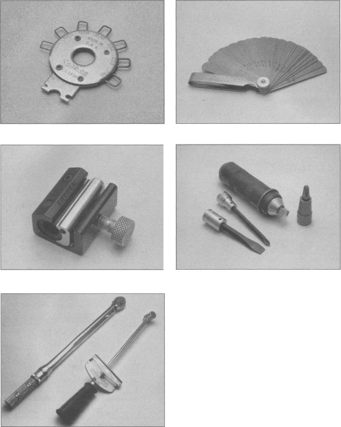
Spark plug gap adjusting tool |
Feeler gauge set |
Control cable pressure luber |
Hand impact screwdriver and bits |
Torque wrenches (left - click type; right - beam type)
If a hose clamp is broken or damaged, do not reuse it. Also, do not reuse hoses that are cracked, split or torn.
Tools
A selection of good tools is a basic requirement for anyone who plans to maintain and repair a motorcycle. For the owner who has few tools, if any, the initial investment might seem high, but when compared to the spiraling costs of routine maintenance and repair, it is a wise one.
To help the owner decide which tools are needed to perform the tasks detailed in this manual, the following tool lists are offered: Maintenance and minor repair, Repair and overhaul and Special. The newcomer to practical mechanics should start off with the Maintenance and minor repair tool kit, which is adequate for the simpler jobs. Then, as confidence and experience grow, the owner can tackle more difficult tasks, buying additional tools as they are needed.
Eventually the basic kit will be built into the Repair and overhaul tool set. Over a period of time, the experienced do-it-yourselfer will assemble a tool set complete enough for most repair and overhaul procedures and will add tools from the Special category when it is felt that the expense is justified by the frequency of use.
Maintenance techniques, tools and working facilities |
0-13 |
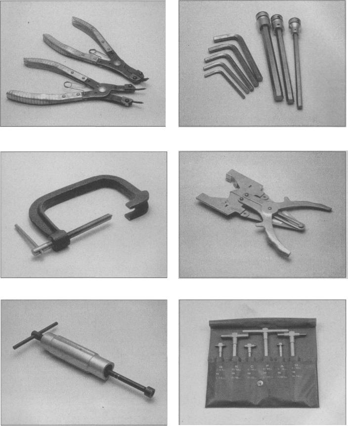
Snap-ring pliers (top - external; bottom - internal) |
Allen wrenches (left) and Allen head sockets (right) |
Valve spring compressor |
Piston ring removal/installation tool |
Piston pin puller |
Telescoping gauges |
0-14 |
Maintenance techniques, tools and working facilities |
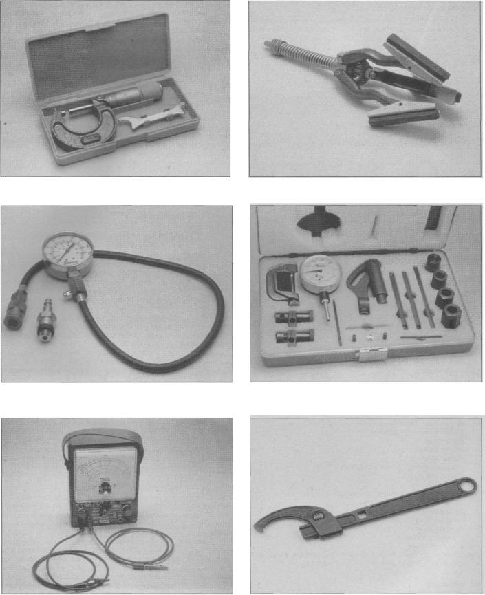
0-to1-inch micrometer |
Cylinder surfacing hone |
Cylinder compression gauge |
Dial indicator set |
Multimeter (volt/ohm/ammeter) |
Adjustable spanner |
Maintenance techniques, tools and working facilities |
0-15 |
Maintenance and minor repair tool kit
The tools in this list should be considered the minimum required for performance of routine maintenance, servicing and minor repair work. We recommend the purchase of combination wrenches (box end and open end combined in one wrench); while more expensive than open-ended ones, they offer the advantages of both types of wrench.
Combination wrench set (6 mm to 22 mm)
Adjustable wrench -8 in
Spark plug socket (with rubber insert)
Spark plug gap adjusting tool Feeler gauge set
Standard screwdriver (5/16 in x 6 in) Phillips screwdriver (No. 2x6 in)
Allen (hex) wrench set (4 mm to 12 mm)
Combination (slip-joint) pliers - 6 in Hacksaw and assortment of blades Tire pressure gauge
Control cable pressure luber Grease gun
Oil can
Fine emery cloth Wire brush
Hand impact screwdriver and bits
Funnel (medium size) Safety goggles
Drain pan
Work light with extension cord
Repair and overhaul tool set
These tools are essential for anyone who plans to perform major repairs and are intended to supplement those in the Maintenance and minor repair tool kit. Included is a comprehensive set of sockets which, though expensive, are invaluable because of their versatility (especially when various extensions and drives are available). We recommend the 3/8 inch drive over the 1/2 inch drive for general motorcycle maintenance and repair (ideally, the mechanic would have a 3/8 inch drive set and a 1/2 inch drive set).
Socket set(s)
Reversible ratchet Extension - 6 in
Universal joint
Torque wrench (same size drive as sockets) Ball pein hammer - 8 oz
Soft-faced hammer (plastic/rubber) Standard screwdriver (1/4 in x 6 in) Standard screwdriver (stubby - 5/16 in)
Phillips screwdriver (No. 3x8 in)
Phillips screwdriver (stubby - No. 2) Pliers - locking
Pliers - lineman's Pliers - needle nose
Pliers - snap-ring (internal and external)
Cold chisel - 1/2 in Scriber
Scraper (made from flattened copper tubing) Center punch
Pin punches (1/16, 1/8, 3/16 in) Steel rule/straightedge - 12 in Pin-type spanner wrench
A selection of files Wire brush (large)
Note: Another tool which is often useful is an electric drill with a chuck capacity of 3/8 inch (and a set of good quality drill bits).
Special tools
The tools in this list include those which are not used regularly, are expensive to buy, or which need to be used in accordance with their manufacturer's instructions. Unless these tools will be used
frequently, it is not very economical to purchase many of them. A consideration would be to split the cost and use between yourself and a friend or friends (i.e. members of a motorcycle club).
This list primarily contains tools and instruments widely available to the public, as well as some special tools produced by the vehicle manufacturer for distribution to dealer service departments. As a result, references to the manufacturer's special tools are occasionally included in the text of this manual. Generally, an alternative method of doing the job without the special tool is offered. However, sometimes there is no alternative to their use. Where this is the case, and the tool can't be purchased or borrowed, the work should be turned over to the dealer service department or a motorcycle repair shop.
Valve spring compressor
Piston ring removal and installation tool Piston pin puller
Telescoping gauges
Micrometers) and/or dial/Vernier calipers
Cylinder surfacing hone
Cylinder compression gauge
Dial indicator set
Multimeter
Adjustable spanner
Manometer or vacuum gauge set
Small air compressor with blow gun and tire chuck
Buying tools
For the do-it-yourselfer who is just starting to get involved in motorcycle maintenance and repair, there are a number of options available when purchasing tools. If maintenance and minor repair is the extent of the work to be done, the purchase of individual tools is satisfactory. If, on the other hand, extensive work is planned, it would be a good idea to purchase a modest tool set from one of the large retail chain stores. A set can usually be bought at a substantial savings over the individual tool prices (and they often come with a tool box). As additional tools are needed, add-on sets, individual tools and a larger tool box can be purchased to expand the tool selection. Building a tool set gradually allows the cost of the tools to be spread over a longer period of time and gives the mechanic the freedom to choose only those tools that will actually be used.
Tool stores and motorcycle dealers will often be the only source of some of the special tools that are needed, but regardless of where tools are bought, try to avoid cheap ones (especially when buying screwdrivers and sockets) because they won't last very long.There are plenty of tools around at reasonable prices, but always aim to purchase items which meet the relevant national safety standards. The expense involved in replacing cheap tools will eventually be greater than the initial cost of quality tools.
It is obviously not possible to cover the subject of tools fully here. For those who wish to learn more about tools and their use, there is a book entitled Motorcycle Workshop Practice Manual (Book no. 1454) available from the publishers of this manual. It also provides an introduction to basic workshop practice which will be of interest to a home mechanic working on any type of motorcycle.
Care and maintenance of tools
Good tools are expensive, so it makes sense to treat them with respect. Keep them clean and in usable condition and store them properly when not in use. Always wipe off any dirt, grease or metal chips before putting them away. Never leave tools lying around in the work area.
Some tools, such as screwdrivers, pliers, wrenches and sockets, can be hung on a panel mounted on the garage or workshop wall, while others should be kept in a tool box or tray. Measuring instruments, gauges, meters, etc. must be carefully stored where they can't be damaged by weather or impact from other tools.
When tools are used with care and stored properly, they will last a very long time. Even with the best of care, tools will wear out if used frequently. When a tool is damaged or worn out, replace it; subsequent jobs will be safer and more enjoyable if you do.
0-16 |
Maintenance techniques, tools and working facilities |
Working facilities
Not to be overlooked when discussing tools is the workshop. If anything more than routine maintenance is to be carried out, some sort of suitable work area is essential.
It is understood, and appreciated, that many home mechanics do not have a good workshop or garage available and end up removing an engine or doing major repairs outside (it is recommended, however, that the overhaul or repair be completed under the cover of a roof).
A clean, flat workbench or table of comfortable working height is an absolute necessity. The workbench should be equipped with a vise that has a jaw opening of at least four inches.
As mentioned previously, some clean, dry storage space is also required for tools, as well as the lubricants, fluids, cleaning solvents, etc. which soon become necessary.
Sometimes waste oil and fluids, drained from the engine or cooling system during normal maintenance or repairs, present a disposal problem. To avoid pouring them on the ground or into a sewage system, simply pour the used fluids into large containers, seal them with caps and take them to an authorized disposal site or service station. Plastic jugs are ideal for this purpose.
Always keep a supply of old newspapers and clean rags available. Old towels are excellent for mopping up spills. Many mechanics use rolls of paper towels for most work because they are readily available and disposable. To help keep the area under the motorcycle clean, a large cardboard box can be cut open and flattened to protect the garage or shop floor.
Whenever working over a painted surface (such as the fuel tank) cover it with an old blanket or bedspread to protect the finish.
Safety first
Professional mechanics are trained in safe working procedures. However enthusiastic you may be about getting on with the job at hand, take the time to ensure that your safety is not put at risk. A moment's lack of attention can result in an accident, as can failure to observe simple precautions.
There will always be new ways of having accidents, and the following is not a comprehensive list of all dangers; it is intended rather to make you aware of the risks and to encourage a safe approach to all work you carry out on your bike.
Essential DOs andDON'Ts
DON'T start the engine without first ascertaining that the transmission is in neutral.
DON'T suddenly remove the filler cap from a hot cooling system - cover it with a cloth and release the pressure gradually first, or you may get scalded by escaping coolant.
DON'T attempt to drain oil until you are sure it has cooled sufficiently to avoid scalding you.
DON'T grasp any part of the engine or exhaust system without first ascertaining that it is cool enough not to burn you.
DON'T allow brake fluid or antifreeze to contact the machine's paint work or plastic components.
DON'T siphon toxic liquids such as fuel, hydraulic fluid or antifreeze by mouth, or allow them to remain on your skin.
DON'T inhale dust - it may be injurious to health (see Asbestos heading).
DON'T allow any spilled oil or grease to remain on the floor - wipe it up right away, before someone slips on it.
DON'T use ill fitting wrenches or other tools which may slip and cause injury.
DON'T attempt to lift a heavy component which may be beyond your capability - get assistance.
DON'T rush to finish a job or take unverified short cuts.
DON'T allow children or animals in or around an unattended vehicle.
DON'T inflate a tire to a pressure above the recommended maximum. Apart from over stressing the carcase and wheel rim, in extreme cases the tire may blow off forcibly.
DO ensure that the machine is supported securely at all times. This is especially important when the machine is blocked up to aid wheel or fork removal.
DO take care when attempting to loosen a stubborn nut or bolt. It is generally better to pull on a wrench, rather than push, so that if you slip, you fall away from the machine rather than onto it.
DO wear eye protection when using power tools such as drill, sander, bench grinder etc.
DO use a barrier cream on your hands prior to undertaking dirty jobs -'it will protect your skin from infection as well as making the dirt easier to remove afterwards; but make sure your hands aren't left slippery. Note that long-term contact with used engine oil can be a health hazard.
DO keep loose clothing (cuffs, ties etc. and long hair) well out of the way of moving mechanical parts.
DO remove rings, wristwatch etc., before working on the vehicleespecially the electrical system.
DO keep your work area tidy - it is only too easy to fall over articles left lying around.
DO exercise caution when compressing springs for removal or installation. Ensure that the tension is applied and released in a controlled manner, using suitable tools which preclude the possibility of the spring escaping violently.
DO ensure that any lifting tackle used has a safe working load rating adequate for the job.
DO get someone to check periodically that all is well, when working alone on the vehicle.
DO carry out work in a logical sequence and check that everything is correctly assembled and tightened afterwards.
DO remember that your vehicle's safety affects that of yourself and others. If in doubt on any point, get professional advice.
0-17
IF, in spite of following these precautions, you are unfortunate enough to injure yourself, seek medical attention as soon as possible.
Asbestos
Certain friction, insulating, sealing and other products - such as brake pads, clutch linings, gaskets, etc. - contain asbestos. Extreme care must be taken to avoid inhalation of dust from such products since it is hazardous to health. If in doubt, assume that they do contain asbestos.
Fire
Remember at all times that gasoline (petrol) is highly flammable.
Never smoke or have any kind of naked flame around, when working on the vehicle. But the risk does not end there - a spark caused by an electrical short-circuit, by two metal surfaces contacting each other, by careless use of tools, or even by static electricity built up in your body under certain conditions, can ignite gasoline (petrol) vapor, which in a confined space is highly explosive. Never use gasoline (petrol) as a cleaning solvent. Use an approved safety solvent.
Always disconnect the battery ground (earth) terminal before working on any part of the fuel or electrical system, and never risk spilling fuel on to a hot engine or exhaust.
It is recommended that a fire extinguisher of a type suitable for fuel and electrical fires is kept handy in the garage or workplace at all times. Never try to extinguish a fuel or electrical fire with water.
Fumes
Certain fumes are highly toxic and can quickly cause unconsciousness and even death if inhaled to any extent. Gasoline
(petrol) vapor comes into this category, as do the vapors from certain solvents such as trichloroethylene. Any draining or pouring of such volatile fluids should be done in a well ventilated area.
When using cleaning fluids and solvents, read the instructions carefully. Never use materials from unmarked containers - they may give off poisonous vapors.
Never run the engine of a motor vehicle in an enclosed space such as a garage. Exhaust fumes contain carbon monoxide which is extremely poisonous; if you need to run the engine, always do so in the open air or at least have the rear of the vehicle outside the workplace.
The battery
Never cause a spark, or allow a naked light near the vehicle's battery. It will normally be giving off a certain amount of hydrogen gas, which is highly explosive.
Always disconnect the battery ground (earth) terminal before working on the fuel or electrical systems (except where noted).
If possible, loosen the filler plugs or cover when charging the battery from an external source. Do not charge at an excessive rate or the battery may burst.
Take care when topping up, cleaning or carrying the battery. The acid electrolyte, even when diluted, is very corrosive and should not be allowed to contact the eyes or skin. Always wear rubber gloves and goggles or a face shield. If you ever need to prepare electrolyte yourself, always add the acid slowly to the water; never add the water to the acid.
Electricity
When using an electric power tool, inspection light etc., always ensure that the appliance is correctly connected to its plug and that, where necessary, it is properly grounded (earthed). Do not use such appliances in damp conditions and, again, beware of creating a spark or applying excessive heat in the vicinity of fuel or fuel vapor. Also ensure that the appliances meet national safety standards.
A severe electric shock can result from touching certain parts of the electrical" system, such as the spark plug wires (HT leads), when the engine is running or being cranked, particularly if components are damp or the insulation is defective. Where an electronic ignition system is used, the secondary (HT) voltage is much higher and could prove fatal.
Motorcycle chemicals and lubricants
A number of chemicals and lubricants are available for use in motorcycle maintenance and repair. They include a wide variety of products ranging from cleaning solvents and degreasers to lubricants and protective sprays for rubber, plastic and vinyl.
Contact point/spark plug cleaner is a solvent used to clean oily film and dirt from points, grime from electrical connectors and oil deposits from spark plugs. It is oil free and leaves no residue. It can also be used to remove gum and varnish from carburetor jets and other orifices.
Carburetor cleaner is similar to contact point/spark plug cleaner but it usually has a stronger solvent and may leave a slight oily reside.
It is not recommended for cleaning electrical components or connections.
Brake system cleaner is used to remove grease or brake fluid from brake system components (where clean surfaces are absolutely necessary and petroleum-based solvents cannot be used); it also leaves no residue.
Silicone-based lubricants are used to protect rubber parts such as hoses and grommets, and are used as lubricants for hinges and locks.
Multi-purpose grease is an all purpose lubricant used wherever grease is more practical than a liquid lubricant such as oil. Some multipurpose grease is colored white and specially formulated to be more resistant to water than ordinary grease.
Gear oil (sometimes called gear lube) is a specially designed oil used in transmissions and final drive units, a s well as other areas where high friction, high temperature lubrication is required. It is available in a number of viscosities (weights) for various applications.
Motor oil, of course, is the lubricant specially formulated for use in the engine. It normally contains a wide variety of additives to prevent corrosion and reduce foaming and wear. Motor oil comes in various weights (viscosity ratings) of from 5 to 80. The recommended weight of the oil depends on the seasonal temperature and the demands on the engine. Light oil is used in cold climates and under light load conditions; heavy oil is used in hot climates and where high loads are encountered. Multi-viscosity oils are designed to have Characteristics of both light and heavy oils and are available in a number of weights from 5W-20 to 20W-50.
Gas (petrol) additives perform several functions, depending on their chemical makeup. They usually contain solvents that help dissolve gum and varnish that build up on carburetor and intake parts.
They also serve to break down carbon deposits that form on the inside surfaces of the combustion chambers. Some additives contain upper cylinder lubricants for valves and piston rings.
Brake fluid is a specially formulated hydraulic fluid that can withstand the heat and pressure encountered in brake systems. Care must be taken that this fluid does not come in contact with painted surfaces or plastics. An opened container should always be resealed to prevent contamination by water or dirt.
Chain lubricants are formulated especially for use on motorcycle final drive chains. A good chain lube should adhere well and have good penetrating qualities to be effective as a lubricant inside the chain and on the side plates, pins and rollers. Most chain lubes are either the foaming type or quick drying type and are usually marketed as sprays.
Degreasers are heavy duty solvents used to remove grease and grime that may accumulate on engine and frame components. They can be sprayed or brushed on and, depending on the type, are rinsed with either water or solvent.
Solvents are used alone or in combination with degreasers to clean parts and assemblies during repair and overhaul. The home mechanic should use only solvents that are non-flammable and that do not produce irritating fumes.
Gasket sealing compounds may be used in conjunction with gaskets, to improve their sealing capabilities, or alone, to seal metal- to-metal joints. Many gasket sealers can withstand extreme heat, some are impervious to gasoline and lubricants, while others are capable of filling and sealing large cavities. Depending on the intended use, gasket sealers either dry hard or stay relatively soft and pliable. They are usually applied by hand, with a brush, or are sprayed on the gasket sealing surfaces.
Thread cement is an adhesive locking compound that prevents threaded fasteners from loosening because of vibration. It is available in a variety of types for different applications.
Moisture dispersants are usually sprays that can be used to dry out electrical components such as the fuse block and wiring connectors. Some types can also be used as treatment for rubber and as a lubricant for hinges, cables and locks.
Waxes and polishes are used to help protect painted and plated surfaces from the weather. Different types of paint may require the use of different types of wax polish. Some polishes utilize a chemical or abrasive cleaner to help remove the top layer of oxidized (dull) paint on older-vehicles. In recent years, many non-wax polishes (that contain a wide variety of chemicals such as polymers and silicones) have been introduced. These non-wax polishes are usually easier to apply and last longer than conventional waxes and polishes.

0-19
Troubleshooting
Contents
Symptom Section
Engine doesn't start or is difficult to start
Starter motor doesn't rotate... |
|
1 |
Starter motor rotates but engine does not turn over |
2 |
|
Starter works but engine won't turn over (seized) |
3 |
|
No fuel flow |
. |
4 |
Engine flooded |
|
5 |
No spark or weak spark |
|
6 |
Compression low |
|
7 |
Stalls after starting |
|
8 |
Rough idle |
|
9 |
Poor running at low speed
Spark weak |
10 |
Fuel/air mixture incorrect |
11 |
Compression low |
12 |
Poor acceleration |
13 |
Poor running or no power at high speed
Symptom |
Section |
Jumps out of gear... |
29 |
Overshifts |
30 |
Abnormal engine noise
Knocking or pinging |
31 |
Piston slap or rattling |
32 |
Valve noise |
33 |
Other noise |
34 |
Abnormal driveline noise
Clutch noise |
35 |
Transmission noise |
36 |
Chain or final drive noise |
37 |
Abnormal frame and suspension noise
Front end noise |
38 |
Shock absorber noise |
39 |
Disc brake noise |
40 |
Firing incorrect |
14 |
Oil level indicator light comes on |
|
|
Fuel/air mixture incorrect |
15 |
Engine lubrication system |
41 |
|
Compression low |
16 |
Electrical system |
42 |
|
Knocking or pinging |
17 |
Excessive exhaust smoke |
|
|
Miscellaneous causes |
18 |
White smoke |
43 |
|
Overheating |
|
Black smoke |
44 |
|
|
Brown srnoke |
45 |
||
Engine overheats |
19 |
|||
Poor handling or stability |
|
|||
Firing incorrect |
20 |
|
||
Fuel/air mixture incorrect |
21 |
Handlebar hard to turn |
46 |
|
Compression too high |
22 |
Handlebar shakes or vibrates excessively |
47 |
|
Engine load excessive |
23 |
Handlebar pulls to one side |
48 |
|
Lubrication inadequate |
24 |
Poor shock absorbing qualities |
49 |
|
Miscellaneous causes |
25 |
Braking problems |
|
|
Clutch problems |
|
|
||
|
Brakes are spongy, don't hold |
50 |
||
Clutch slipping |
26 |
Brake lever pulsates |
51 |
|
Clutch not disengaging completely |
27 |
Brakes drag |
52 |
|
Gear shifting problems |
|
Electrical problems |
|
|
|
Battery dead or weak |
53 |
||
Doesn't go into gear, or lever doesn't return |
28 |
|||
Battery overcharged |
54 |
0-20 |
Troubleshooting |
Engine doesn't start or is difficult to start
1 Starter motor does not rotate
1Engine kill switch Off.
2Fuse blown. Check fuse block (Chapter 8).
3Battery voltage low. Check and recharge battery (Chapter 8).
4Starter motor defective. Make sure the wiring to the starter is secure. Test starter relay (Chapter 8). If the relay is good, then the fault is in the wiring or motor.
5Starter relay faulty. Check it according to the procedure in
Chapter 8.
6Starter switch not contacting. The contacts could be wet, corroded or dirty. Disassemble and clean the switch (Chapter 8).
7Wiring open or shorted. Check all wiring connections and harnesses to make sure that they are dry, tight and not corroded. Also check for broken or frayed wires that can cause a short to ground (see wiring diagram, Chapter 8).
8Ignition switch defective. Check the switch according to the procedure in Chapter 8. Replace the switch with a new one if it is defective.
9Engine kill switch defective. Check for wet, dirty or corroded contacts. Clean or replace the switch as necessary (Chapter 8).
2 Starter motor rotates but engine does not turn over
1Starter motor clutch defective. Inspect and repair or replace
(Chapter 8).
2Damaged idler or starter gears. Inspect and replace the damaged parts (Chapter 2).
3Starter works but engine won't turn over (seized)
Seized engine caused by one or more internally damaged components. Failure due to wear, abuse or lack of lubrication. Damage can include seized valves, valve lifters, camshaft, pistons, crankshaft, connecting rod bearings, or transmission gears or bearings. Refer to Chapter 2 for engine disassembly.
4 No fuel flow
1No fuel in tank.
2Fuel tap vacuum hose (if equipped) broken or disconnected.
3Tank cap air vent obstructed. Usually caused by dirt or water. Remove it and clean the cap vent hole.
4Inline fuel filter clogged. Replace the filter (Chapter 1).
5Electric fuel pump not working (if equipped). Test it according to the procedures in Chapter 8.
6Fuel line clogged. Pull the fuel line loose and carefully blow through it.
7Inlet needle valve clogged. For both of the valves to be clogged, either a very bad batch of fuel with an unusual additive has been used, or some other foreign material has entered the tank. Many times after a machine has been stored for many months without running, the fuel turns to a varnish-like liquid and forms deposits on the inlet needle valves and jets. The carburetors should be removed and overhauled if draining the float chambers doesn't solve the problem.
5 Engine flooded
1Fuel level too high. Check and adjust as described in Chapter 3.
2Inlet needle valve worn or stuck open. A piece of dirt, rust or other debris can cause the inlet needle to seat improperly, causing excess fuel to be admitted to the float bowl. In this case, the float chamber
should be cleaned and the needle and seat inspected. If the needle and seat are worn, then the leaking will persist and the parts should be replaced with new ones (Chapter 3).
3 Starting technique incorrect. Under normal circumstances (i.e., if all the carburetor functions are sound) the machine should start with little or no throttle. When the engine is cold, the choke should be operated and the engine started without opening the throttle. When the engine is at operating temperature, only a very slight amount of throttle should be necessary. If the engine is flooded, turn the fuel tap off and hold the throttle open while cranking the engine. This will allow additional air to reach the cylinders. Remember to turn the fuel tap back on after the engine starts.
6 No spark or weak spark
1Ignition switch Off.
2Engine kill switch turned to the Off position.
3Battery voltage low. Check and recharge battery as necessary
(Chapter 8).
4Spark plug dirty, defective or worn out. Locate reason for fouled plug(s) using spark plug condition chart and follow the plug maintenance procedures in Chapter 1.
5Spark plug cap or secondary (HT) wiring faulty. Check condition. Replace either or both components if cracks or deterioration are evident (Chapter 4).
6Spark plug cap not making good contact. Make sure that the plug cap fits snugly over the plug end.
7Igniter defective. Check the unit, referring to Chapter 4 for details.
8Pickup coil(s) defective. Check the unit(s), referring to Chapter 4 for details.
9Ignition coil(s) defective. Check the coils, referring to Chapter 4.
10Ignition or kill switch shorted. This is usually caused by water, corrosion, damage or excessive wear. The switches can be disassembled and cleaned with electrical contact cleaner. If cleaning does not help, replace the switches (Chapter 8),
11Wiring shorted or broken between:
a)Ignition switch and engine kill switch (or blown fuse)
b)Igniter and engine kill switch
c)Igniter and ignition coil
d)Ignition coil and plug
e)Igniter and pickup coil(s)
Make sure that all wiring connections are clean, dry and tight. Look for chafed and broken wires (Chapters 4 and 8).
7 Compression low
1Spark plug loose. Remove the plug and inspect the threads. Reinstall and tighten to the specified torque (Chapter 1).
2Cylinder head not sufficiently tightened down. If a cylinder head is suspected of being loose, then there's a chance that the gasket or head is damaged if the problem has persisted for any length of time. The head nuts and bolts should be tightened to the proper torque in the correct sequence (Chapter 2).
3Improper valve clearance. This means that the valve is not closing completely and compression pressure is leaking past the valve. Check and adjust the valve clearances (Chapter 1).
4Cylinder and/or piston worn. Excessive wear will cause compression pressure to leak past the rings. This is usually accompanied by worn rings as well. A top end overhaul is necessary
(Chapter 2).
5Piston rings worn, weak, broken, or sticking. Broken or sticking piston rings usually indicate a lubrication or carburetion problem that causes excess carbon deposits or seizures to form on the pistons and rings. Top end overhaul is necessary (Chapter 2).
6Piston ring-to-groove clearance excessive. This is caused by excessive wear of the piston ring lands. Piston replacement is necessary (Chapter 2).
Troubleshooting |
0-21 |
7Cylinder head gasket damaged. If one of the heads is allowed to become loose, or if excessive carbon build-up on a piston crown and combustion chamber causes extremely high compression, the head gasket may leak. Retorquing the head is not always sufficient to restore the seal, so gasket replacement is necessary (Chapter 2).
8Cylinder head warped. This is caused by overheating or improperly tightened head nuts and bolts. Machine shop resurfacing or head replacement is necessary (Chapter 2).
9Valve spring broken or weak. Caused by component failure or wear; the spring(s) must be replaced (Chapter 2).
10Valve not seating properly. This is caused by a bent valve (from over-revving or improper valve adjustment), burned valve or seat (improper carburetion) or an accumulation of carbon deposits on the seat (from carburetion or lubrication problems). The valves must be cleaned and/or replaced and the seats serviced if possible (Chapter 2).
8 Stalls after starting
1Improper choke action. Make sure the choke lever (XV535) or choke cable (all others) is getting a full stroke and staying in the out position.
2Ignition malfunction. See Chapter 4.
3Carburetor malfunction. See Chapter 3.
4Fuel contaminated. The fuel can be contaminated with either dirt or water, or can change chemically if the machine is allowed to sit for several months or more. Drain the tank and float bowls (Chapter 3).
5Intake air leak. Check for loose carburetor-to-intake joint connections, loose or missing vacuum gauge access port cap or hose, or loose carburetor top (Chapter 3).
6Engine idle speed incorrect. Turn throttle stop screw until the engine idles at the specified rpm (Chapter 1).
9 Rough idle
1Ignition malfunction. See Chapter 4.
2Idle speed incorrect. See Chapter 1.
3Carburetors not synchronized. Adjust carburetors with vacuum gauge or manometer set as described in Chapter 1.
4Carburetor malfunction. See Chapter 3.
5Fuel contaminated. The fuel can be contaminated with either dirt or water, or can change chemically if the machine is allowed to sit for several months or more. Drain the tank and float bowls (Chapter 3).
6Intake air leak. Check for loose carburetor-to-intake joint connections, loose or missing vacuum gauge access port cap or hose, or loose carburetor top (Chapter 3).
7Air cleaner clogged. Service or replace air filter element (Chapter 1).
Poor running at low speed
10 Spark weak
1Battery voltage low. Check and recharge battery (Chapter 8).
2Spark plug fouled, defective or worn out. Refer to Chapter 1 for spark plug maintenance.
3Spark plug cap or high tension wiring defective. Refer to Chapters
1and 4 for details on the ignition system.
4Spark plug cap not making contact.
5Incorrect spark plug. Wrong type, heat range or cap configuration. Check and install correct plugs listed in Chapter 1. A cold plug or one with a recessed firing electrode will not operate at low speeds without fouling.
6Igniter defective. See Chapter 4.
7Pickup coil(s) defective. See Chapter 4.
8Ignition coil(s) defective. See Chapter 4.
11 Fuel/air mixture incorrect
1Pilot screw(s) out of adjustment (Chapters 1 and 3).
2Pilot jet or air passage clogged. Remove and overhaul the carburetors (Chapter 3).
3Air bleed holes clogged. Remove carburetor and blow out all passages (Chapter 3).
4Air cleaner clogged, poorly sealed or missing.
5Air cleaner-to-carburetor boot poorly sealed. Look for cracks, holes or loose clamps and replace or repair defective parts.
6Fuel level too high or too low. Adjust the floats (Chapter 3).
7Fuel tank air vent obstructed. Make sure that the air vent passage in the filler cap is open.
8Carburetor intake joints loose. Check for cracks, breaks, tears or loose clamps or bolts. Repair or replace the rubber boots.
12 Compression low
1Spark plug loose. Remove the plug and inspect the threads. Reinstall and tighten to the specified torque (Chapter 1).
2Cylinder head not sufficiently tightened down. If the cylinder head is suspected of being loose, then there's a chance that the gasket and head are damaged if the problem has persisted for any length of time.
The head nuts and bolts should be tightened to the proper torque in the correct sequence (Chapter 2).
3Improper valve clearance. This means that the valve is not closing completely and compression pressure is leaking past the valve. Check and adjust the valve clearances (Chapter 1).
4Cylinder and/or piston worn. Excessive wear will cause compression pressure to leak past the rings. This is usually accompanied by worn rings as well. A top end overhaul is necessary
(Chapter 2).
5Piston rings worn, weak, broken, or sticking. Broken or sticking piston rings usually indicate a lubrication or carburetion problem that causes excess carbon deposits or seizures to form on the pistons and rings. Top end overhaul is necessary (Chapter 2).
6Piston ring-to-groove clearance excessive. This is caused by excessive wear of the piston ring lands. Piston replacement is necessary (Chapter 2).
7Cylinder head gasket damaged. If a head is allowed to become loose, or if excessive carbon build-up on the piston crown and combustion chamber causes extremely high compression, the head gasket may leak. Retorquing the head is not always sufficient to restore the seal, so gasket replacement is necessary (Chapter 2).
8Cylinder head warped. This is caused by overheating or improperly tightened head nuts and bolts. Machine shop resurfacing or head replacement is necessary (Chapter 2).
9Valve spring broken or weak. Caused by component failure or wear; the spring(s) must be replaced (Chapter 2).
10Valve not seating properly. This is caused by a bent valve (from over-revving or improper valve adjustment), burned valve or seat (improper carburetion) or an accumulation of carbon deposits on the seat (from carburetion, lubrication problems). The valves must be cleaned and/or replaced and the seats serviced if possible (Chapter 2).
13 Poor acceleration
1Carburetors leaking or dirty. Overhaul the carburetors (Chapter 3).
2Timing not advancing. The pickup coil(s) or the igniter may be defective. If so, they must be replaced with new ones, as they can't be repaired.
3Carburetors not synchronized. Adjust them with a vacuum gauge set or manometer (Chapter 1).
4Engine oil viscosity too high. Using a heavier oil than that recommended in Chapter 1 can damage the oil pump or lubrication system and cause drag on the engine.
0-22 |
Troubleshooting |
5 Brakes dragging. Usually caused by debris which has entered the brake piston sealing boot, or from a warped disc or bent axle. Repair as necessary (Chapter 6).
Poor running or no power at high speed
14 Firing incorrect
1Air filter restricted. Clean or replace filter (Chapter 1).
2Spark plug fouled, defective or worn out. See Chapter 1 for spark plug maintenance.
3Spark plug cap or secondary (HT) wiring defective. See Chapters
1and 4 for details of the ignition system.
4Spark plug cap not in good contact. See Chapter 4.
5Incorrect spark plug. Wrong type, heat range or cap configuration. Check and install correct plugs listed in Chapter 1. A cold plug or one with a recessed firing electrode will not operate at low speeds without fouling.
6Igniter defective. See Chapter 4.
7Ignition coil(s) defective. See Chapter 4. ,
15 Fuel/air mixture incorrect
1Main jet clogged. Dirt, water or other contaminants can clog the main jets. Clean the fuel tap filter, the float bowl area, and the jets and carburetor orifices (Chapter 3).
2Main jet wrong size. The standard jetting is for sea level atmospheric pressure and oxygen content.
3Throttle shaft-to-carburetor body clearance excessive. Refer to Chapter 3 for inspection and part replacement procedures.
4Air bleed holes clogged. Remove and overhaul carburetors (Chapter 3).
5Air cleaner clogged, poorly sealed, or missing.
6Air cleaner-to-carburetor boot poorly sealed. Look for cracks, holes or loose clamps, and replace or repair defective parts.
7Fuel level too high or too low. Adjust the float(s) (Chapter 3).
8Fuel tank air vent obstructed. Make sure the air vent passage in the filler cap is open.
9Carburetor intake joints loose. Check for cracks, breaks, tears or loose clamps or bolts. Repair or replace the rubber boots (Chapter 3).
10Fuel tap clogged. Remove the tap and clean it (Chapter 1).
11Fuel line clogged. Pull the fuel line loose and carefully blow through it.
16 Compression low
1Spark plug loose. Remove the plug and inspect the threads. Reinstall and tighten to the specified torque (Chapter 1).
2Cylinder head not sufficiently tightened down. If a cylinder head is suspected of being loose, then there's a chance that the gasket and head are damaged if the problem has persisted for any length of time. The head nuts and bolts should be tightened to the proper torque in the correct Sequence (Chapter 2).
3Improper valve clearance. This means that the valve is not closing completely and compression pressure is leaking past the valve. Check and adjust the valve clearances (Chapter 1).
4Cylinder and/or piston worn. Excessive wear will cause compression pressure to leak past the rings. This is usually accompanied by worn rings as well. A top end overhaul is necessary (Chapter 2).
5Piston rings worn, weak, broken, or sticking. Broken or sticking piston rings usually indicate a lubrication or carburetion problem that causes excess carbon deposits or seizures to form on the pistons and rings. Top end overhaul is necessary (Chapter 2).
6Piston ring-to-groove clearance excessive. This is caused by excessive wear of the piston ring lands. Piston replacement is
necessary (Chapter 2).
7Cylinder head gasket damaged. If a head is allowed to become loose, or if excessive carbon build-up on the piston crown and combustion chamber causes extremely high compression, the head gasket may leak. Retorquing the head is not always sufficient to restore the seal, so gasket replacement is necessary (Chapter 2).
8Cylinder head warped. This is caused by overheating or improperly tightened head nuts and bolts. Machine shop resurfacing or head replacement is necessary (Chapter 2).
9Valve spring broken or weak. Caused by component failure or wear; the spring(s) must be replaced (Chapter 2).
10Valve not seating properly. This is caused by a bent valve (from over-revving or improper valve adjustment), burned valve or seat
(improper carburetion) or an accumulation of carbon deposits on the seat (from carburetion or lubrication problems). The valves must be cleaned and/or replaced and the seats serviced if possible (Chapter 2).
17 Knocking or pinging
1Carbon build-up in combustion chamber. Use of a fuel additive that will dissolve the adhesive bonding the carbon particles to the crown and chamber is the easiest way to remove the build-up.
Otherwise, the cylinder head will have to be removed and decarbonized (Chapter 2).
2Incorrect or poor quality fuel. Old or improper grades of fuel can cause detonation. This causes the piston to rattle, thus the knocking or pinging sound. Drain old fuel and always use the recommended fuel grade.
3Spark plug heat range incorrect. Uncontrolled detonation indicates the plug heat range is too hot. The plug in effect becomes a glow plug, raising cylinder temperatures. Install the proper heat range plug (Chapter 1).
4Improper air/fuel mixture. This will cause the cylinder to run hot, which leads to detonation. Clogged jets or an air leak can cause this imbalance. See Chapter 3.
18 Miscellaneous causes
1Throttle valve doesn't open fully. Adjust the cable slack (Chapter 1).
2Clutch slipping. May be caused by a cable that is improperly adjusted or loose or worn clutch components. Refer to Chapter 2 for cable replacement and clutch overhaul procedures.
3Timing not advancing.
4Engine oil viscosity too high. Using a heavier oil than the one recommended in Chapter 1 can damage the oil pump or lubrication system and cause drag on the engine.
5Brakes dragging. Usually caused by debris which has entered the brake piston sealing boot, or from a warped disc or bent axle. Repair as necessary.
Overheating
19 Engine overheats
1Engine oil level low. Check and add oil (Chapter 1).
2Wrong type of oil. If you're not sure what type of oil is in the engine, drain it and fill with the correct type (Chapter 1).
3Air leak at carburetor intake joints. Check and tighten or replace as necessary (Chapter 3).
4Fuel level low. Check and adjust if necessary (Chapter 3).
5Worn oil pump or clogged oil passages. Replace pump or clean passages as necessary.
6Clogged external oil lines (if equipped). Remove and check for foreign material (see Chapter 2).
7Carbon build-up in combustion chambers. Use of a fuel additive
Troubleshooting |
0-23 |
that will dissolve the adhesive bonding the carbon particles to the piston crowns and chambers is the easiest way to remove the buildup. Otherwise, the cylinder heads will have to be removed and decarbonized (Chapter 2).
pressure. Replace cam, bushing or cylinder head. Abnormal wear could be caused by oil starvation at high rpm from low oil level or improper viscosity or type of oil (Chapter 1).
4 Crankshaft and/or bearings worn. Same problems as paragraph 3. Check and replace crankshaft and/or bearings (Chapter 2).
20 Firing incorrect
1Spark plug fouled, defective or worn out. See Chapter 1 for spark plug maintenance.
2Incorrect spark plug (see Chapter 1).
3Faulty ignition coil(s) (Chapter 4).
25 Miscellaneous causes
Modification to exhaust system. Most aftermarket exhaust systems cause the engine to run leaner, which make them run hotter. When installing an accessory exhaust system, always rejet the carburetors.
21 Fuel/air mixture incorrect
1Main jet clogged. Dirt, water and other contaminants can clog the main jets. Clean the fuel tap filter, the float bowl area and the jets and carburetor orifices (Chapter 3).
2Main jet wrong size. The standard jetting is for sea level atmospheric pressure and oxygen content.
3Air cleaner poorly sealed or missing.
4Air cleaner-to-carburetor boot poorly sealed. Look for cracks, holes or loose clamps and replace or repair.
5Fuel level too low. Adjust the float(s) (Chapter 3).
6Fuel tank air vent obstructed. Make sure that the air vent passage in the filler cap is open.
7Carburetor intake joints loose. Check for cracks, breaks, tears or loose clamps or bolts. Repair or replace the rubber boots (Chapter 3).
22 Compression too high
1Carbon build-up in combustion chamber. Use of a fuel additive that will dissolve the adhesive bonding the carbon particles to the piston crown and chamber is the easiest way to remove the build-up. Otherwise, the cylinder head will have to be removed and decarbonized (Chapter 2).
2Improperly machined head surface or installation of incorrect gasket during engine assembly.
23 Engine load excessive
1 Clutch slipping. Can be caused by damaged, loose or worn clutch oonents. Refer to Chapter 2 for overhaul procedures.
Engine oil level too high. The addition of too much oil will cause pressurization of the crankcase and inefficient engine operation. Check
Specifications and drain to proper level (Chapter 1).
3Engine oil viscosity too high. Using a heavier oil than the one recommended in Chapter 1 can damage the oil pump or lubrication system as well as cause drag on the engine.
4Brakes dragging. Usually caused by debris which has entered the brake piston sealing boot, or from a warped disc or bent axle. Repair as necessary.
24 Lubrication inadequate
1Engine oil level too low. Friction caused by intermittent lack of lubrication or from oil that is overworked can cause overheating. The oil provides a definite cooling function in the engine. Check the oil level (Chapter 1).
2Poor quality engine oil or incorrect viscosity or type. Oil is rated not only according to viscosity but also according to type. Some oils are not rated high enough for use in this engine. Check the Specifications section and change to the correct oil (Chapter 1).
3Camshaft or journals worn. Excessive wear causing drop in oil
Clutch problems
26 Clutch slipping
1Friction plates worn or warped. Overhaul the clutch assembly (Chapter 2).
2Steel plates worn or warped (Chapter 2).
3Clutch spring(s) broken or weak. Old or heat-damaged spring(s) (from slipping clutch) should be replaced with new ones (Chapter 2).
4Clutch release mechanism defective. Replace any defective parts (Chapter 2).
5Clutch boss or housing unevenly worn. This causes improper engagement of the plates. Replace the damaged or worn parts (Chapter 2).
27 Clutch not disengaging completely
1Clutch lever play excessive (see Chapter 1). Clutch cable improperly adjusted (see Chapter 1).
2Clutch plates warped or damaged. This will cause clutch drag, which in turn will cause the machine to creep. Overhaul the clutch assembly (Chapter 2).
3Usually caused by a sagged or broken spring(s). Check and replace the spring(s) (Chapter 2).
4Engine oil deteriorated. Old, thin, worn out oil will not provide proper lubrication for the discs, causing the clutch to drag. Replace the oil and filter (Chapter 1).
5Engine oil viscosity too high. Using a thicker oil than recommended in Chapter 1 can cause the plates to stick together, putting a drag on the engine. Change to the correct viscosity oil (Chapter 1).
6Clutch housing seized on shaft. Lack of lubrication, severe wear or damage can cause the housing to seize on the shaft. Overhaul of the clutch, and perhaps transmission, may be necessary to repair the damage (Chapter 2).
7Clutch release mechanism defective. Worn or damaged release mechanism parts can stick and fail to apply force to the pressure plate.
Overhaul the release mechanism (Chapter 2).
8Loose clutch boss nut. Causes housing and boss misalignment putting a drag on the engine. Engagement adjustment continually varies. Overhaul the clutch assembly (Chapter 2).
Gear shifting problems
28 Doesn't go into gear or lever doesn't return
1- Clutch not disengaging. See Section 27.
2 Shift fork(s) bent or seized. Often caused by dropping the machine or from lack of lubrication. Overhaul the transmission (Chapter 2).
0-24 |
Troubleshooting |
3Gear(s) stuck on shaft. Most often caused by a lack of lubrication or excessive wear in transmission bearings and bushings. Overhaul the transmission (Chapter 2).
4Shift cam binding. Caused by lubrication failure or excessive wear. Replace the cam and bearing (Chapter 2).
5Shift lever return spring weak or broken (Chapter 2).
6Shift lever broken. Splines stripped out of lever or shaft, caused by allowing the lever to get loose or from dropping the machine. Replace necessary parts (Chapter 2).
7Shift mechanism pawl broken or worn. Full engagement and rotary movement of shift drum results. Replace shaft assembly (Chapter 2).
8Pawl spring broken. Allows pawl to float, causing sporadic shift operation. Replace spring (Chapter 2).
29 Jumps out of gear
1Shift fork(s) worn. Overhaul the transmission (Chapter 2).
2Gear groove(s) worn. Overhaul the transmission (Chapter 2).
3Gear dogs or dog slots worn or damaged. The gears should be inspected and replaced. No attempt should be made to service the worn parts.
30 Overshifts
1Pawl spring weak or broken (Chapter 2).
2Shift drum stopper lever not functioning (Chapter 2).
Abnormal engine noise
31 Knocking or pinging
1Carbon build-up in combustion chamber. Use of a fuel additive that will dissolve the adhesive bonding the carbon particles to the piston crown and chamber is the easiest way to remove the build-up. Otherwise, the cylinder head will have to be removed and decarbonized (Chapter 2).
2Incorrect or poor quality fuel. Old or improper fuel can cause detonation. This causes the pistons to rattle, thus the knocking or pinging sound. Drain the old fuel and always use the recommended grade fuel (Chapter 1).
3Spark plug heat range incorrect. Uncontrolled detonation indicates that the plug heat range is too hot. The plug in effect becomes a glow plug, raising cylinder temperatures. Install the proper heat range plug (Chapter 1).
4Improper air/fuel mixture. This will cause the cylinders to run hot and lead to detonationrClogged jets or an air leak can cause this imbalance. See Chapter 3.
32 Piston slap or rattling
1Cylinder-to-piston clearance excessive. Caused by improper assembly. Inspect and overhaul top end parts (Chapter 2).
2Connecting rod bent. Caused by over-revving, trying to start a badly flooded engine or from ingesting a foreign object into the combustion chamber. Replace the damaged parts (Chapter 2).
3Piston pin or piston pin bore worn or seized from wear or lack of lubrication. Replace damaged parts (Chapter 2).
4Piston ring(s) worn, broken or sticking. Overhaul the top end (Chapter 2).
5Piston seizure damage. Usually from lack of lubrication or overheating. Replace the pistons and bore the cylinders, as necessary (Chapter 2).
6 Connecting rod upper or lower end clearance excessive. Caused by excessive wear or lack of lubrication. Replace worn parts.
33 Valve noise
1Incorrect valve clearances. Adjust the clearances by referring to Chapter 1.
2Valve spring broken or weak. Check and replace weak valve springs (Chapter 2).
3Camshaft, bushing or cylinder head worn or damaged. Lack of lubrication at high rpm is usually the cause of damage. Insufficient oil or failure to change the oil at the recommended intervals are the chief causes.
34 Other noise
1Cylinder head gasket leaking.
2Exhaust pipe leaking at cylinder head connection. Caused by improper fit of pipe(s) or loose exhaust flange. All exhaust fasteners should be tightened evenly and carefully. Failure to do this will lead to a leak.
3Crankshaft runout excessive. Caused by a bent crankshaft (from over-revving) or damage from an upper cylinder component failure.
Can also be attributed to dropping the machine on either of the crankshaft ends.
4Engine mounting bolts or nuts loose. Tighten all engine mounting bolts and nuts to the specified torque (Chapter 2).
5Crankshaft bearings worn (Chapter 2).
6Camshaft chain tensioner(s) defective. Replace according to the procedure in Chapter 2.
7Camshaft chain, sprockets or guides worn (Chapter 2).
Abnormal driveline noise
35 Clutch noise
1Clutch housing/friction plate clearance excessive (Chapter 2).
2Loose or damaged clutch pressure plate and/or bolts (Chapter 2).
36 Transmission noise
1Bearings worn. Also includes the possibility that the shafts are worn. Overhaul the transmission (Chapter 2).
2Gears worn or chipped (Chapter 2).
3Metal chips jammed in gear teeth. Probably pieces from a broken clutch, gear or shift mechanism that were picked up by the gears. This will cause early bearing failure (Chapter 2).
4Engine oil level too low. Causes a howl from transmission. Also affects engine power and clutch operation (Chapter 1).
37 Final drive noise
1Chain not adjusted properly (if equipped) (Chapter 1).
2Engine sprocket or rear sprocket loose (chain drive models). Tighten fasteners (Chapter 5).
3Sprocket(s) worn (chain drive models). Replace sprocket(s). (Chapter 5).
4Rear sprocket warped (chain drive models). Replace (Chapter 5).
5Wheel coupling (cush drive) worn (chain drive models). Replace coupling (Chapter 5).
6Final drive oil level low (shaft drive models).
7Final drive gear lash out of adjustment (shaft drive models).
8Final drive gears damaged or worn (shaft drive models).
Troubleshooting |
0-25 |
Abnormal frame and suspension noise
38 Front end noise
1Low fluid level or improper viscosity oil in forks. This can sound like spurting and is usually accompanied by irregular fork action (Chapter 5).
2Spring weak or broken. Makes a clicking or scraping sound. Fork oil, when drained, will have a lot of metal particles in it (Chapter 5).
3Steering head bearings loose or damaged. Clicks when braking.
Check and adjust or replace as necessary (Chapter 5).
4Fork triple clamps loose. Make sure all triple clamp pinch bolts are tight (Chapter 5).
5Fork tube bent. Good possibility if machine has been dropped.
Replace tube with a new one (Chapter 5).
6Front axle or axle clamp bolt loose. Tighten them to the specified torque (Chapter 6).
39 Shock absorber noise
1Fluid level incorrect. Indicates a leak caused by defective seal.
Shock will be covered with oil. Replace shock (Chapter 5).
2Defective shock absorber with internal damage. This is in the body of the shock and can't be remedied. The shock must be replaced with a new one (Chapter 5).
3Bent or damaged shock body. Replace the shock with a new one
(Chapter 5).
40 Brake noise
1Squeal caused by pad shim not installed or positioned correctly (Chapter 6).
2Squeal caused by dust on brake pads. Usually found in combination with glazed pads. Clean using brake cleaning solvent
(Chapter 6).
3Contamination of brake pads. Oil, brake fluid or dirt causing brake to chatter or squeal. Clean or replace pads (Chapter 6).
4Pads glazed. Caused by excessive heat from prolonged use or from contamination. Do not use sandpaper, emery cloth, carborundum cloth or any other abrasive to roughen the pad surfaces as abrasives will stay in the pad material and damage the disc. A very fine flat file can be used, but pad replacement is suggested as a cure (Chapter 6).
5Disc warped. Can cause a chattering, clicking or intermittent squeal. Usually accompanied by a pulsating lever and uneven braking.
Replace the disc (Chapter 6).
6Drum brake linings worn or contaminated. Can cause scraping or squealing. Replace the shoes (Chapter 6).
7Drum brake linings warped or worn unevenly. Can cause chattering. Replace the linings (Chapter 6).
8Brake drum out of round. Can cause chattering. Replace brake drum (Chapter 6).
9Loose or worn wheel bearings. Check and replace as needed (Chapter 6).
Oil level indicator light comes on
41 Engine lubrication system
1Yamaha XV700 through 1100 models use an oil level light rather than an oil pressure light.
2Engine oil level low. Inspect for leak or other problem causing low oil level and add recommended oil (Chapters 1 and 2).
42 Electrical system
1Oil level switch defective. Check the switch according to the procedure in Chapter 8. Replace it if it's defective.
2Oil level indicator light circuit defective. Check for pinched, shorted, disconnected or damaged wiring (Chapter 8).
Excessive exhaust smoke
43 White smoke
1Piston oil ring worn. The ring may be broken or damaged, causing oil from the crankcase to be pulled past the piston into the combustion chamber. Replace the rings with new ones (Chapter 2).
2Cylinders worn, cracked, or scored. Caused by overheating or oil starvation. If worn or scored, the cylinders will have to be rebored and new pistons installed. If cracked, the cylinder block will have to be replaced (see Chapter 2).
3Valve oil seal damaged or worn. Replace oil seals with new ones (Chapter 2).
4Valve guide worn. Perform a complete valve job (Chapter 2).
5Engine oil level too high, which causes the oil to be forced past the rings. Drain oil to the proper level (Chapter 1).
6Head gasket broken between oil return and cylinder. Causes oil to be pulled into the combustion chamber. Replace the head gasket and check the head for warpage (Chapter 2).
7Abnormal crankcase pressurization, which forces oil past the rings. Clogged breather or hoses usually the cause (Chapter 2).
44 Black smoke
1Air cleaner clogged. Clean or replace the element (Chapter 1).
2Main jet too large or loose. Compare the jet size to the Specifications (Chapter 3).
3Choke stuck, causing fuel to be pulled through choke circuit (Chapter 3).
4Fuel level too high. Check and adjust the float level as necessary (Chapter 3).
5Inlet needle held off needle seat. Clean the float bowls and fuel line and replace the needles and seats if necessary (Chapter 3).
45 Brown smoke
1Main jet too small or clogged. Lean condition caused by wrong size main jet or by a restricted orifice. Clean float bowl and jets and compare jet size to Specifications (Chapter 3).
2Fuel flow insufficient. Fuel inlet needle valve stuck closed due to chemical reaction with old fuel. Float level incorrect. Restricted fuel line. Clean line and float bowl and adjust floats if necessary.
3Carburetor intake manifolds loose (Chapter 3).
4Air cleaner poorly sealed or not installed (Chapter 1).
Poor handling or stability
46 Handlebar hard to turn
1Steering stem locknut too tight (Chapter 5).
2Bearings damaged. Roughness can be felt as the bars are turned from side-to-side. Replace bearings and races (Chapter 5).
3. Races dented or worn. Denting results from wear in only one position (e.g., straight ahead), from a collision or hitting a pothole or from dropping the machine. Replace races and bearings (Chapter 5).
4 Steering stem lubrication inadequate. Causes are grease getting
0-26 |
Troubleshooting |
hard from age or being washed out by high pressure car washes.
Disassemble steering head and repack bearings (Chapter 5).
5Steering stem bent. Caused by a collision, hitting a pothole or by dropping the machine. Replace damaged part. Don't try to straighten the steering stem (Chapter 5).
6Front tire air pressure too low (Chapter 1).
47 Handlebar shakes or vibrates excessively
1Tires worn or out of balance (Chapter 1 or 6).
2Swingarm bearings worn. Replace worn bearings by referring to
Chapter 6.
3Rim(s) warped or damaged. Inspect wheels for runout (Chapter 6).
4Wheel bearings worn. Worn front or rear wheel bearings can cause poor tracking. Worn front bearings will cause wobble (Chapter 6).
5Handlebar clamp bolts or bracket nuts loose (Chapter 5).
6Steering stem or fork clamps loose. Tighten them to the specified torque (Chapter 5).
7Motor mount bolts loose. Will cause excessive vibration with increased engine rpm (Chapter 2).
4Contaminated pads. Caused by contamination with oil, grease, brake fluid, etc. Clean or replace pads. Clean disc thoroughly with brake cleaner (Chapter 6).
5Brake fluid deteriorated. Fluid is old or contaminated. Drain system, replenish with new fluid and bleed the system (Chapter 6).
6Master cylinder internal parts worn or damaged causing fluid to bypass (Chapter 6).
7Master cylinder bore scratched by foreign material or broken spring. Repair or replace master cylinder (Chapter 6).
8Disc warped. Replace disc (Chapter 6).
51 Brake lever or pedal pulsates
1Disc warped. Replace disc (Chapter 6).
2Axle bent. Replace axle (Chapter 5).
3Brake caliper bolts loose (Chapter 6).
4Brake caliper shafts damaged or sticking, causing caliper to bind.
Lube the shafts or replace them if they are corroded or bent (Chapter 6).
5Wheel warped or otherwise damaged (Chapter 6).
6Wheel bearings damaged or worn (Chapter 6).
7Brake drum out of round. Replace brake drum (Chapter 6).
48 Handlebar pulls to one side
1Frame bent. Definitely suspect this if the machine has been dropped. May or may not be accompanied by cracking near the bend. Replace the frame (Chapter 5).
2Wheel out of alignment. Caused by improper location of axle spacers or from bent steering stem or frame (Chapter 5).
3Swingarm bent or twisted. Caused by age (metal fatigue) or impact damage. Replace the swingarm (Chapter 5).
4Steering stem bent. Caused by impact damage or by dropping the motorcycle. Replace the steering stem (Chapter 5).
5Fork leg bent. Disassemble the forks and replace the damaged parts (Chapter 5).
6Fork oil level uneven. Check and add or drain as necessary
(Chapter 5).
49 Poor shock absorbing qualities
1Too hard:
a)Fork oil level excessive (Chapter 5).
b)Fork oil viscosity too high. Use a lighter oil (see the Specifications in Chapter 1).
c)Fork tube bent. Causes a harsh, sticking feeling (Chapter 5).
d)Shock shaft or body bent or damaged (Chapter 5).
e)Fork internal damage (Chapter 5).
f)Shock internal damage.
g)Tire pressure too high (Chapters 1 and 6).
2Too soft:
a)Fork or shock oil insufficient and/or leaking (Chapter 5).
b)Fork oil level too low (Chapter 5).
c)Fork oil viscosity too light (Chapter 5).
d)Fork springs weak or broken (Chapter 5).
Braking problems
50 Front brakes are spongy, don't hold
1 Air in brake line. Caused by inattention to master cylinder fluid level or by leakage. Locate problem and bleed brakes (Chapter 6).
2Pad or disc worn (Chapters 1 and 6).
3Brake fluid leak. See paragraph 1.
52 Brakes drag
1Master cylinder piston seized. Caused by wear or damage to piston or cylinder bore (Chapter 6).
2Lever balky or stuck. Check pivot and lubricate (Chapter 6).
3Brake caliper binds. Caused by inadequate lubrication or damage to caliper shafts (Chapter 6).
4Brake caliper piston seized in bore. Caused by wear or ingestion of dirt past deteriorated seal (Chapter 6),
5Brake pad damaged. Pad material separated from backing plate. Usually caused by faulty manufacturing process or from contact with chemicals. Replace pads (Chapter 6).
6Pads improperly installed (Chapter 6).
7Rear brake pedal free play insufficient (Chapter 1).
8Rear brake springs weak. Replace brake springs (Chapter 6).
Electrical problems
53 Battery dead or weak
1Battery faulty. Caused by sulfated plates which are shorted through sedimentation or low electrolyte level. Also, broken battery terminal making only occasional contact (Chapter 8).
2Battery cables making poor contact (Chapter 8).
3Load excessive. Caused by addition of high wattage lights or other electrical accessories.
4Ignition switch defective. Switch either grounds/earths internally or fails to shut off system. Replace the switch (Chapter 8).
5Regulator/rectifier defective (Chapter 8).
6Stator coil open or shorted (Chapter 8).
7Wiring faulty. Wiring grounded or connections loose in ignition, charging or lighting circuits (Chapter 8).
54 Battery overcharged
1Regulator/rectifier defective. Overcharging is noticed when battery gets excessively warm or boils over (Chapter 8).
2Battery defective. Replace battery with a new one (Chapter 8).
3Battery amperage too low, wrong type or size. Install manufacturer's specified amp-hour battery to handle charging load (Chapter 8).

1-1
Chapter 1
Tune-up and routine maintenance
Contents
Section
Air filter element - servicing |
14 |
Battery electrolyte level/specific gravity - check |
4 |
Brake lever and pedal position and play - check and adjustment. |
7 |
Brake pads and shoes - wear check |
5 |
Brake system - general check |
6 |
Carburetor synchronization - check and adjustment |
20 |
Clutch - check and adjustment |
10 |
Crankcase ventilation system - inspection |
21 |
Cylinder compression - check |
15 |
Drive chain and sprockets (chain drive models) - check, |
|
adjustment and lubrication |
11 |
Engine oil/filter - change |
13 |
Exhaust system - check |
22 |
Fasteners - check |
24 |
Final drive oil (shaft drive models) - check and change |
12 |
|
Section |
Fluid levels - check |
3 |
Fuel system - check and filter cleaning or replacement |
25 |
Idle speed - check and adjustment |
19 |
Introduction to tune-up and routine maintenance |
2 |
Lubrication - general |
17 |
Shift linkage adjustment |
27 |
Spark plugs - replacement |
16 |
Steering head bearings - check, adjustment and lubrication |
23 |
Suspension adjustments |
28 |
Suspension - check |
26 |
Throttle and choke operation/grip freeplay - check |
|
. and adjustment |
9 |
Tires/wheels - general check |
8 |
Valve clearances - check and adjustment |
18 |
Yamaha XV Routine maintenance intervals |
1 |

1-2 |
Chapter 1 Tune-up and routine maintenance |
Specifications
XV535
Engine
Spark plugs Type
Gap
Valve clearances (COLD engine) Intake
Exhaust Engine idle speed
Cylinder compression pressure (at sea level)
Standard Maximum...
Minimum
Maximum difference between cylinders Carburetor synchronization
Vacuum at idle speed
Maximum vacuum difference between cylinders
Cylinder numbering (from rear to front of bike)...
Miscellaneous
Brake pedal position.. |
. |
Shift pedal position |
|
Freeplay adjustments |
|
Throttle grip |
|
Clutch lever |
|
Front brake lever |
|
Rear brake pedal |
.... |
Battery electrolyte specific gravity |
|
Minimum tire tread depth* |
|
Tire pressures (cold) |
|
Front |
|
1987 and 1988 US, all UK models... |
|
1989 and later US models |
|
Rear |
|
Up to 90 kg (198 lbs) |
|
1987 and 1988 US, all UK models |
|
1989 and later US models |
. |
Above 90 kg (198 lbs) or high speed riding |
|
Torque specifications
Oil drain plug |
|
Oil filter cover bolts |
|
Spark plugs |
|
Steering head bearing ring nuts |
|
Initial torque |
|
Final torque |
|
Steering stem bolt |
|
Valve adjuster locknuts |
. |
Rocker cover bolts |
|
Final drive filler and drain plugs |
|
Recommended lubricants and fluids
Fuel type |
|
US |
. |
UK |
|
Fuel capacity |
|
1987 and 1988 models |
|
Total......... |
|
Reserve |
|
1989 and later models |
|
Total |
. |
Reserve.. |
|
Engine/transmission oil |
|
Type |
|
NGK BP7ES or ND W22EP-U
0.7 to 0.8 mm (0.028 to 0.032 inch)
0.07to 0.12 mm (0.003 to 0.005 inch)
0.12to 0.17 mm (0.005 to 0.007 inch) 1150 to 1250 rpm
10.75Bars (156 psi)
11.78Bars (171 psi)
9.78Bars (142 psi)
0.96Bars (14 psi)
230 mm Hg (9.06 inch Hg)
10 mm Hg (0.39 inch Hg)
1-2
38 mm (1.5 inch) above the top of the footpeg
50 to 60 mm (2.0 to 2.4 inches) above the top of the footpeg
2 to 5 mm (0.08 to 0.20 inch)
2 to 3 mm (0.08 to 0.12 inch)
2 to 5 mm (0.08 to 0.20 inch)
20 to 30 mm (0.8 to 1.2 inches) 1.280 at 20-degrees C (68-degrees F) 1 mm (0.04 inch)
1.93Bars (28 psi)
1.99Bars (29 psi)
2.2Bars (32 psi)
2.27Bars (33 psi)
2.48bars (36 psi)
43 Nm (31 ft-lbs)
10Nm (7.2 ft-lbs)
12.5Nm (9 ft-lbs)
38 Nm (27 ft-lbs)
10 Nm (7.2 ft-lbs)
54 Nm (39 ft-lbs)
14 Nm (10 ft-lbs)
10 Nm (7.2 ft-lbs)
23 Nm (17 ft-lbs)
Unleaded
Regular
8.6 liters (2.3 US gal, 1.9 Imp gal)
2.0liters (0.5 US gal, 0.4 Imp gal)
13.5liters (3.6 US gal, 3.0 Imp gal)
2.5liters (0.7 US gal, 0.5 Imp gal)
API grade SE or SF

Chapter 1 Tune-up and routine maintenance |
1-3 |
Viscosity
Consistently below 15 degrees C (60 degrees F) Consistently above 5 degrees C (40 degrees F)
Capacity |
|
With filter change |
|
Oil change only |
|
Brake fluid |
.. |
Final gear |
|
Type |
|
Capacity |
|
Wheel bearings |
|
Swingarm pivot bearings |
. |
Cables and lever pivots |
|
Sidestand/centerstand pivots |
|
Brake pedal/shift lever pivots |
|
Throttle grip |
|
SAE 10W30
SAE 20W40
2.8liters (3.0 US qt, 5.0 Imperial pt)
2.6liters (2.7 US qt, 4.6 Imperial pt)
DOT 4
SAE 80 API GL-4 hypoid gear oil 0.19 liters (0.2 US qt, 0.34 Imp pt
Medium weight, lithium-based multi-purpose grease Medium weight, lithium-based multi-purpose grease
Chain and cable lubricant or 10W30 motor oil
Chain and cable lubricant or 10W30 motor oil Chain and cable lubricant or 10W30 motor oil Multi-purpose grease or dry film lubricant
'In the UK, tread depth must be at least 1 mm over 3/4 of the tread breadth all the way around the tire, with no bald patches.
1981 through 1983 XV750 through 1000 models and all TR1 Engine
Spark plugs |
|
|
Type |
|
NGK BP7ES or ND W22EP-U |
Gap... |
|
0.7 to 0.8 mm (0.028 to 0.032 inch) |
Valve clearances (COLD engine) |
|
|
Intake |
|
0.10 mm (0.004 inch) |
Exhaust |
|
0.15 mm (0.006 inch) |
Engine idle speed |
.. |
950 to 1050 rpm |
Cylinder compression pressure (at sea level) |
|
|
XV750 and TR1 |
|
Not specified |
XV920 |
. |
9.30 Bars (135 psi) at 300 rpm |
Carburetor synchronization |
|
|
Vacuum at idle speed |
|
" 180 +/-10 mm Hg (7.09 +/- 0.4 inch Hg) |
Maximum vacuum difference between cylinders |
10 mm Hg (0.4 inch Hg) |
|
Cylinder numbering (from rear to front of bike) |
1-2 |
|
Miscellaneous
Brake pedal position |
Not specified |
|
Shift pedal position |
Not specified |
|
Freeplay adjustments |
|
|
Throttle grip |
Not specified |
|
Clutch lever |
2 to 3 |
mm (0.08 to 0.12 inch) |
Front brake lever |
5 to 8 |
mm (0.20 to 0.30 inch) |
Rear brake pedal |
20 to 30 mm (0.8 to 1.2 inches) |
|
Battery electrolyte specific gravity |
1.280 at 20-degrees C (68-degrees F) |
|
Minimum tire tread depth* |
1 mm (0.04 inch) |
|
Tire pressures (cold)
XV750, XV920 K and MK
Front |
|
|
Up to 90 kg (198 lbs) load |
1.79 |
Bars (26 psi) |
90 to 160 kg (198 to 353 lbs) load |
1.93 Bars (28 psi) |
|
High speed riding |
2.20 Bars (32 psi) |
|
Rear |
|
|
Up to 90 kg (198 lbs) |
1.93 |
Bars (28 psi) |
90 to 160 kg (198 to 353 lbs) |
2.48 |
bars (36 psi) |
High speed riding |
2.20 Bars (32 psi) |
|
XV920J |
|
|
F r o n t ' |
|
|
Up to 90 kg (198 lbs) load |
1.79 |
Bars (26 psi) |
90 to 213 kg (198 to 470 lbs) load |
1.93 Bars (28 psi) |
|
High speed riding |
2.20 Bars (32 psi) |
|
Rear |
|
|
Up to 90 kg (198 lbs) |
1.93 |
Bars (28 psi) |
90 to 213 kg (198 to 470 lbs) |
2.76 |
bars (40 psi) |
High speed riding |
2.48 Bars (36 psi) |
|
 Loading...