


CONTENTS
VOICE COMMON................................................... |
3 |
NAME................................................................ |
5 |
CONFIGURATION............................................. |
5 |
EFFECT (Type & Depth).................................... |
5 |
PITCH BEND..................................................... |
6 |
WHEEL (Amplitude & Pitch Modulation)........... |
6 |
AFTER TOUCH (Amplitude & |
|
Pitch Modulation, Pitch & Level Control)....... |
7 |
ENVELOPE (Attack & Release Rates)................. |
7 |
RANDOM (Element, Level & Detune)................ |
8 |
VOICE VECTOR..................................................... |
9 |
LEVEL SPEED (Vector Rate)........................... |
11 |
LEVEL RECORD............................................. |
11 |
LEVEL EDIT (Step, X-axis, Y-axis & Time)..... |
11 |
DETUNE SPEED (Vector Rate)........................ |
13 |
DETUNE RECORD.......................................... |
13 |
DETUNE EDIT |
|
(Step, X-axis, Y-axis & Time)....................... |
13 |
ELEMENT TONE................................................ |
15 |
WAVE TYPE.................................................... |
17 |
ELEMENT COPY............................................. |
19 |
FREQUENCY SHIFT........................................ |
19 |
VOLUME......................................................... |
20 |
PAN.................................................................. |
20 |
VELOCITY SENSITIVITY............................... |
20 |
AFTER TOUCH SENSITIVITY........................ |
21 |
TONE (FM Elements B and D Only)................. |
21 |
LFO (Low Frequency Oscillator) AM Depth, |
|
PM Depth, Type, Delay, Rate & Speed.......... |
22 |
ELEMENT ENVELOPE....................................... |
25 |
TYPE................................................................ |
27 |
ENVELOPE COPY........................................... |
28 |
DELAY (Delay Rate & Element ON/OFF)......... |
28 |
INITIAL LEVEL.............................................. |
28 |
ATTACK (Level & Rate).................................. |
29 |
DECAY 1 (Level & Rate).................................. |
29 |
DECAY 2 (Level & Rate).................................. |
29 |
RELEASE RATE.............................................. |
30 |
LEVEL SCALING............................................ |
30 |
RATE SCALING.............................................. |
31 |
MULTI................................................................. |
33 |
NAME.............................................................. |
35 |
EFFECT (Type & Depth).................................. |
35 |
VOICE NUMBER............................................. |
35 |
MIDI RECEIVE CHANNEL............................. |
36 |
VOLUME......................................................... |
36 |
DETUNE.......................................................... |
37 |
NOTE LIMIT (Low & High)............................ |
37 |
NOTE SHIFT.................................................... |
37 |
UTILITY SETUP................................................. |
39 |
MASTER TUNE............................................... |
41 |
TRANSPOSE.................................................... |
41 |
MEMORY CARD |
|
(Save, Load, Format, & Bank)....................... |
41 |
VOICE INITIALIZE......................................... |
43 |
MULTI INITIALIZE........................................ |
44 |
MEMORY PROTECT (Internal & Card)........... |
45 |
FACTORY VOICE & MULTI RESTORE.......... |
45 |
UTILITY RECALL............................................... |
47 |
VOICE RECALL (Voice or Multi).................... |
49 |
UTILITY MIDI.................................................... |
51 |
MIDI ON/OFF................................................... |
53 |
BASIC RECEIVE CHANNEL........................... |
53 |
TRANSMIT CHANNEL................................... |
53 |
LOCAL CONTROL ON/OFF............................. |
54 |
MIDI PROGRAM CHANGE............................. |
54 |
MIDI CONTROL CHANGE.............................. |
54 |
AFTER TOUCH ON/OFF.................................. |
55 |
PITCH BEND ON/OFF...................................... |
55 |
EXCLUSIVE ON/OFF....................................... |
55 |
ALL V/M TRANSMIT...................................... |
56 |
1 VOICE TRANSMIT....................................... |
56 |
APPENDIX........................................................... |
57 |
VOICE LIST..................................................... |
59 |
MULTI LIST.................................................... |
66 |
WAVEFORM LIST........................................... |
67 |
SPECIFICATIONS............................................ |
69 |
ERROR MESSAGES......................................... |
70 |
INDEX............................................................. |
71 |
MIDI DATA FORMAT..................................... |
73 |
MIDI IMPLEMENTATION CHART................ |
76 |
i

About This Manual
The SY35 Feature Reference manual individually describes the SY35 functions in detail, providing a summary, operating procedure, and additional details for each function. It is divided into eight main sections, each describing the various functions within a particular SY35 edit or utility mode.
1.VOICE COMMON [Page 3]
2.VOICE VECTOR [Page 9]
3.ELEMENT TONE [Page 15]
4.ELEMENT ENVELOPE [Page 25]
5.MULTI [Page 33]
6.UTILITY SETUP [Page 39]
7.UTILITY RECALL [Page 47]
8.UTILITY MIDI [Page 51]
We recommend that you start by going through the Getting Started manual in order to become familiar with the SY35 and the way it works, then you can refer to the Feature Reference manual from time to time to get details on functions you’ve never used before, or refresh your memory about functions that you don’t use very often.
Each section of this manual has its own table of contents, so you should be able to locate any particular function quickly and easily. Functions and references can also be located by referring to the index at the back of the manual.
ii

VOICE COMMON
Feature
Reference Manual
1
VOICE COMMON
2
VOICE COMMON
VOICE COMMON
The VOICE COMMON mode provides access to a range of parameters that affect the selected voice as a whole. Detailed programming of individual elements is provided by the ELEMENT TONE and ELEMENT ENVELOPE edit modes.
NAME............................................................................................................................ |
5 |
CONFIGURATION......................................................................................................... |
5 |
EFFECT (Type & Depth)............................................................................................... |
5 |
PITCH BEND................................................................................................................. |
6 |
WHEEL (Amplitude & Pitch Modulation)...................................................................... |
6 |
AFTER TOUCH (Amplitude & Pitch Modulation, Pitch & Level Control).................... |
7 |
ENVELOPE (Attack & Release Rates)............................................................................ |
7 |
RANDOM (Element, Level & Detune)........................................................................... |
8 |
3
VOICE COMMON
NAME
VC>VOICE NAME
I23 Initial
Summary: Assigns a name of up to 8 characters to the current voice.
Settings: The following characters are available for use in voice names:
(Space) !"#¢%&'()*+,-./0123456789:;<=>?Å ABCDEFGHIJKLMNOPQRSTUVWXYZ[Á]^_« abcdefghijklmnopqrstuvwxyz“|‘Ÿ˚
Procedure: Use the [4] and [6] cursor keys to place the underline cursor under the character to be changed. Use the [–1/NO] and [+1/YES] keys to select the desired character. Continue until the entire voice name has been programmed.
Details: It’s a good idea to give your voices names that make them easily identifiable. If you’ve created a new voice that combines piano and organ elements, for example, you could call it something like “PianOrg”.
When selecting characters, scrolling will pause at the beginning of each character group (capitals, lower case, numbers, and symbols).
CONFIGURATION
VC>CONFIGURATION
A-B-C-D
Summary: Selects the two-element (A-B) or fourelement (A-B-C-D) voice configuration.
Settings: A-B, A-B-C-D
Procedure: Use the [6] key to move the cursor to the lower display line. Use the [–1/NO] and [+1/YES] keys to select the desired configuration.
Details: In the 2-element “A-B” configuration, element A is AWM and element B is FM. In the 4- element “A-B-C-D” configuration elements A and B are the same as in the “A-B” configuration, while element C is AWM and element D is FM.
A-B: A = AWM, B = FM.
A-B-C-D: A = AWM, B = FM, C = AWM, D = FM.
EFFECT (Type & Depth)
VC>VOICE EFFECT
Rev Hall Dep=1
Summary: Selects one of sixteen digital effects, and sets the depth of the selected effect for the current voice.
5
VOICE COMMON
Settings: Effect type:
Rev Hall |
(Reverb Hall) |
Rev Room |
(Reverb Room) |
Rev Plate |
(Reverb Plate) |
Rev Club |
(Reverb Club) |
Rev Metal |
(Reverb Metal) |
Delay 1 |
(Short Single Delay) |
Delay 2 |
(Long Delay) |
Delay 3 |
(Long Delay) |
Doubler |
(Doubler) |
Ping-Pong |
(Ping Pong Delay) |
Pan Ref |
(Panned Reflections) |
Early Ref |
(Early Reflections) |
Gate Rev |
(Gated Reverb) |
Dly&Rev 1 |
(Delay & Reverb 1) |
Dly&Rev 2 |
(Delay & Reverb 2) |
Dist&Rev |
(Distortion & Reverb) |
Depth: 0 … 7
Procedure: Use the [4] and [6] cursor keys to place the underline cursor under the effect type or depth parameter. Use the [–1/NO] and [+1/YES] keys to select the desired effect or effect depth.
Details: Setting the depth parameter to “ 0 ” is equivalent to turning the effect OFF. A depth setting of “7” produces the greatest effect.
PITCH BEND
VC@PITCH BEND
Range= 2
Summary: Sets the range of the pitch bend wheel.
Settings: 0 … 12 max.*
Procedure: Use the [6] key to move the cursor to the lower display line. Use the [–1/NO] and [+1/YES] keys to select the desired pitch bend range.
Details: Each increment from “0” to “12” represents a semitone. A setting of “0” produces no
pitch |
bend. |
A |
setting |
of “ 1 2 ” |
allows |
a |
|
maximum pitch |
bend of |
plus |
or |
minus one |
|||
octave, |
while |
a |
setting |
of |
“ 4 ” |
allows |
a |
maximum pitch bend of plus or minus a major third.
*This range may be more limited in some cases. An exclamation mark (!) will appear after the range value when the limit is reached.
WHEEL (Amplitude & Pitch Modulation)
VC@WHEEL
AM=on PM=ON
Summary: Assigns the modulation wheel to amplitude and/or pitch modulation.
Settings: AM (Amplitude Modulation): off, on PM (Pitch Modulation): off, on
Procedure: Use the [4] and [6] cursor keys to place the underline cursor under the AM or PM parameter. Use the [–1/NO] and [+1/YES] keys to turn the selected parameter on or off.
Details: Amplitude modulation produces a tremolo effect while pitch modulation produced a vibrato effect. This function allows the modulation wheel to be assigned to produce either or both. This is only an “off/on” switch, however, and the maximum depth of modulation to be applied must be set using the LFO AM Depth and PM Depth parameters in the ELEMENT TONE edit mode.
When the modulation wheel is assigned to amplitude or pitch modulation, LFO modulation can only be applied via the wheel.
If both WHEEL and AFTER TOUCH are assigned to modulation control, the controller via which the highest modulation level is applied will take priority when both are used simultaneously.
6

VOICE COMMON
AFTER TOUCH (Amplitude & Pitch Modulation, Pitch & Level Control)
VC>AFTER TOUCH
AM=on PM=on ->
Summary: Assigns keyboard after-touch to amplitude modulation, pitch modulation, pitch control, or level control — or any combination of the above.
Settings: AM (Amplitude Modulation): off, on PM (Pitch Modulation): off, on
Pit (Pitch Control): –12 … 0 … +12 max.* Lev (Level Control): off, on
Procedure: Use the [4] and [6] cursor keys to place the underline cursor under the AM, PM, Pit, or Lev parameter. The arrows at either end of the display mean that more parameters can be accessed by scrolling in the indicated direction. Use the [–1/NO] and [+1/YES] keys to turn the AM, PM, and/or Lev parameter on or off, or to select the desired Pit control range.
Details: As with the modulation wheel, amplitude modulation produces a tremolo effect while pitch modulation produced a vibrato effect. The harder you press a key, the deeper the modulation. This is only an “off/on” switch, however, and the maximum depth of modulation to be applied must be set using the LFO AM Depth and PM Depth parameters in the ELEMENT TONE edit mode.
When after touch is assigned to amplitude or pitch modulation, LFO modulation can only be applied via after touch.
The Pit parameter allows keyboard after touch to be used for note bending. The greater the key pressure the greater the amount of pitch bend. Positive values produce an upward bend when key pressure is applied, and minus values produce a downward bend. Each increment from represents a semitone. A setting of “ 0 ” produces no pitch bend. A setting of “12” allows a maximum upward pitch bend of one octave, while a setting of “ – 4 ” allows a maximum downward pitch bend of a major third.
When the Lev parameter is turned on it becomes possible to control the level of the sound over a limited range by keyboard after touch. The amount and direction (i.e. an increase or decrease) of level change depends on the setting of the AFTER TOUCH SENSITIVITY parameter in the ELEMENT TONE edit mode.
If both WHEEL and AFTER TOUCH are assigned to modulation control, the controller via which the highest modulation level is applied will take priority when both are used simultaneously.
*This range may be more limited in some cases. An exclamation mark (!) will appear after the range value when the limit is reached.
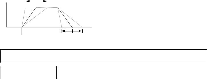
ENVELOPE (Attack & Release Rates)
VC>ENVELOPE
AR= 0 RR= 0
Summary: Sets the overall attack and release rates for the current voice.
Settings: AR (Attack Rate): –99 … 0 … +99 max.* RR (Release Rate): –99 … 0 … +99 max.*
Procedure: Use the [4] and [6] cursor keys to place the underline cursor under the AR or RR parameter. Use the [–1/NO] and [+1/YES] keys to set the selected parameter as required.
Details: Although much more detailed envelope
programming capability is available for individual elements (see the ELEMENT ENVELOPE edit mode), these functions provide an easy way to adjust the most important envelope parameters for the overall voice. Positive values produce a faster attack or release time, while negative values produce a slower attack or release time. You might want to lengthen the release time of a voice, for example, to produce a lingering sustain effect after you release the keys.
7
VOICE COMMON
Please note that the AR parameter will have no effect on elements in which the INITIAL LEVEL parameter (page 28) is set to 99.
Faster |
|
AR |
|
Slower |
|||
attack. |
|
|
attack. |
||||
|
|
|
|
|
|
|
Key OFF |
|
|
|
|
|
|
|
|
|
|
|
|
|
|
||
+99 |
0 |
–99 |
|
||||
|
|
|
|
|
|
|
|
LEVEL
Envelope
TIME
Key ON
+99 |
0 |
–99 |
|
Faster |
RR |
Slower |
|
release. |
release |
||
|
*This range may be more limited in some cases. An exclamation mark (!) will appear after the range value when the limit is reached.
RANDOM (Element, Level & Detune)
VC>RANDOM
ELEMENT
Summary: Automatically produces random combinations of elements, level vectors, or detune vectors.
Settings: None.
Procedure: Use the [4] and [6] cursor keys to place the left parameter on the lower display line, then use the [–1/NO] and [+1/YES] keys to select ELEMENT, LEVEL or DETUNE. Press the [6] to move the cursor to “Y/N,” then press the [+1/YES] key to generate random values of the select type. A new set of random values is generated each time the [+1/YES] key is pressed while the cursor is in this position. Pressing the [–1/NO] returns the cursor to the left parameter.
Details: This function is actually a very useful programming aid. It allows you try out a virtually unlimited variety of element combinations or level/detune vectors by simply pressing a single key. The random element combinations, in particular, can produce some very surprising and often pleasant results.
When the “A-B” voice configuration is selected (see CONFIGURATION on page 5), random element combinations will always consist of only two elements. When the “A-B-C-D” voice configuration is selected, random element generation will produce combinations of four elements.
8
VOICE VECTOR
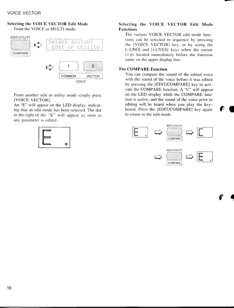
VOICE VECTOR
The VOICE VECTOR edit mode allows recording and fine editing of dynamic level and detune vectors.
LEVEL SPEED (Vector Rate)......................................................................................... |
11 |
LEVEL RECORD............................................................................................................ |
11 |
LEVEL EDIT (Step, X-axis, Y-axis & Time).................................................................. |
11 |
DETUNE SPEED (Vector Rate)..................................................................................... |
13 |
DETUNE RECORD........................................................................................................ |
13 |
DETUNE EDIT (Step, X-axis, Y-axis & Time).............................................................. |
13 |
9
VOICE VECTOR
LEVEL SPEED (Vector Rate)
VV>LEVEL SPEED
Vector Rate 30ms
Summary: Sets the time between level vector steps.
Settings: 10 … 160 milliseconds (in 10-millisecond steps)
Procedure: Use the [6] key to move the cursor to the lower display line. Use the [–1/NO] and [+1/YES] keys to select the desired vector rate.
Details: Each dynamic vector is composed of up to 50 “steps” corresponding to points along the path followed by the vector control. This function sets the initial time between each step. The Time parameter in the LEVEL EDIT function, described later, allows the length of individual steps to be edited. The vector rate parameter can be changed even after recording a vector, producing a corresponding change in the spacing between the steps.
The LEVEL SPEED parameter can also be used to change the playback speed of a pre-recorded vector.
LEVEL RECORD
VV>LEVEL REC
STBY REC PLAY
Summary: Allows recording of a dynamic level vector.
Settings: STBY, REC, PLAY
Procedure: Use the [4] and [6] cursor keys to place the underline cursor under STBY. The vector control LEVEL mode will be automatically selected and you can rehearse the vector sweep you wish to record.
Move the cursor to REC. Recording will actually begin as soon as you play a key on the keyboard. When you release the key or when 50 steps have been recorded (See “LEVEL SPEED” above), recording will end and the cursor will move to the PLAY position. You can now play the keyboard to hear how the vector sweep you just recorded sounds.
Details: The amount of time available for recording depends both on the vector rate setting and how much the vector control is moved.
LEVEL EDIT (Step, X-axis, Y-axis & Time)
●Step
VVL.ED A B
B C
C D
D 1 X 0 Y 0 End
Summary: Selects any of the 50 steps in a recorded level vector for editing.
Settings: 1 … 50
Procedure: Use the [4] and [6] cursor keys to place the underline cursor under the leftmost value on the lower display line (Step). Use the [–1/NO] and [+1/YES] keys to select the step to be edited.
11

VOICE VECTOR
Details: Step 1 is the first step recorded and step 50 is the last. Experience will give you a feel for relating specific points in a dynamic vector to the corresponding steps.
●X-axis & Y-axis
VVL.ED A B
B C
C D
D 1 X 0 Y 0 End
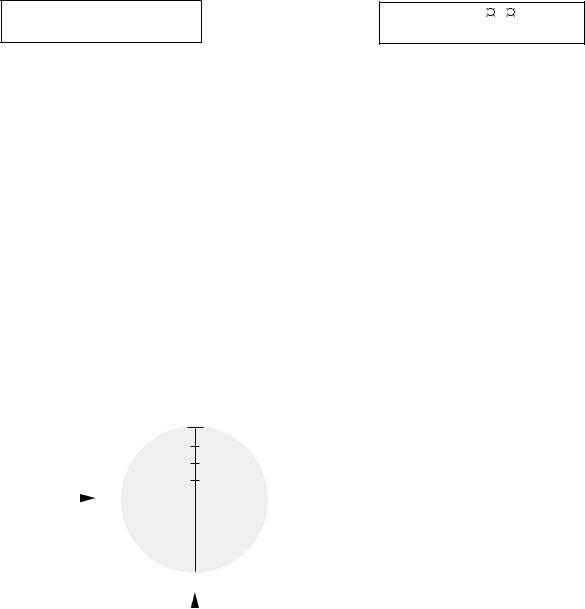
Summary: These parameters define the position of the currently selected step on the X and Y axes of the level vector control range.
Settings: –31 … 0 … +31
Procedure: After selecting the step to be recorded as described in the previous function, use the [4] and [6] cursor keys to place the underline cursor under the X or Y parameter. Use the [–1/NO] and [+1/YES] keys to set the value as required.
Details: On the X (D-C) axis, a setting of –31 places the step as far as possible toward the D element while a setting of +31 places it as far as possible toward the C element. The Y (A-B) axis values work in the same way: a setting of –31 places the step as far as possible toward the B element while a setting of +31 places it as far as possible toward the A element. In both axes a setting of 0 places the step at center position.
A
+31
X axis |
|
D |
|
|
|
0 |
|
|
|
C |
|||||
|
|
|
|
|
|
|
|
|
|
|
|
|
|||
|
|
–31 |
|
|
|
|
|
|
|
–31 |
+31 |
||||
|
|
|
|
|
|
|
|
||||||||
|
|
|
|
|
|
|
|
|
|
|
|
|
|
||
|
|
|
|
|
|
|
|
|
|
|
|
|
|
||
|
|
|
|
|
|
|
|
|
|
|
|
|
|
||
|
|
|
|
|
|
|
|
|
|
|
|
|
|
||
|
|
|
|
|
|
|
|
B |
|
|
|
||||
|
|
|
|
|
|
|
|
|
|
||||||
|
|
|
|
|
|
|
|
|
|
|
|||||
|
|
|
|
|
|
Y axis |
|
|
|
||||||
●Time
VVL.ED A B C D
D 1 X 0 Y 0 End
Summary: Multiplies the vector rate setting of the current level vector step only. Also allows vectors to be looped or ended at the current step.
Settings: 1 … 254, Rep, End
Procedure: Use the [4] and [6] cursor keys to place the underline cursor under the rightmost value on the lower display line (Time). Use the [–1/NO] and [+1/YES] keys to select the required time value, repeat, or end.
Details: Time values multiply the vector rate setting for the current step. If the vector rate parameter is set to 30ms, for example, setting the time parameter to 2 results in a step length of 60ms, setting it to 3 results in a step length of 90ms, and so on. Since the maximum time value is 254, extremely long steps can be created.
If you select the “End” setting, the vector will end at the current step.
The “ R e p ” setting causes the vector to loop back to the first step from the current step, repeating continuously.
12
VOICE VECTOR
DETUNE SPEED (Vector rate)
VV>DETUNE SPEED
Vector Rate 30ms
Summary: Sets the time between detune vector steps.
Settings: 10 … 160 milliseconds
Procedure: Use the [6] key to move the cursor to the lower display line. Use the [–1/NO] and [+1/YES] keys to select the desired vector rate.
Details: Each automatic vector sweep is composed of up to 50 “steps,” corresponding to equallyspaced points along the path followed by the vector control. This function sets the initial time between each step.
DETUNE RECORD
VV>DETUNE REC
STBY REC PLAY
Summary: Allows recording of a dynamic detune vector.
Settings: STBY, REC, PLAY
Procedure: Use the [4] and [6] cursor keys to place the STBY. The vector control DETUNE mode will be automatically selected and you can rehearse the vector sweep you wish to record.
Move the cursor to REC. Recording will actually begin as soon as you play a key on the key
board. When you release the key or when all 50 steps have been recorded (See “DETUNE SPEED” above), recording will end and the cursor will move to the PLAY position. You can now play the keyboard to hear how the vector sweep you just recorded sounds.
Details: The amount of time available for recording depends both on the vector rate setting and how much the vector control is moved.
Moving the vector control towards an element raises the pitch of that element while lowering the pitch of the others.
DETUNE EDIT (Step, X-axis, Y-axis & Time)
●Step
VVD.ED A B
B C
C D
D
1 X 0 Y 0 End
Summary: Selects any of the 50 steps in a recorded detune vector for editing.
Settings: 1 … 50
Procedure: Use the [4] and [6] cursor keys to place the underline cursor under the leftmost value on the lower display line (Step). Use the [–1/NO] and [+1/YES] keys to select the step to be edited.
Details: Step 1 is the first step recorded and step 50 is the last. Experience will give you a feel for relating specific points in a dynamic vector to the corresponding steps.
13
VOICE VECTOR
●X-axis & Y-axis
VVD.ED A B
B C
C D
D 1 X 0 Y 0 End
Summary: These parameters define the position of the currently selected step on the X and Y axes of the detune vector control range.
Settings: –31 … 0 … +31
Procedure: Use the [4] and [6] cursor keys to place the underline cursor under the X or Y parameter. Use the [–1/NO] and [+1/YES] keys to set the value as required.
Details: On the X (D-C) axis, a setting of –31 places the step as far as possible toward the D element while a setting of +31 places it as far as possible toward the C element. The Y (A-B) axis values work in the same way: a setting of –31 places the step as far as possible toward the B element while a setting of +31 places it as far as possible toward the A element. In both axes a setting of 0 places the step at center position.
A
+31
X axis |
|
D |
|
0 |
|
|
|
C |
|||||||
|
|
|
|
|
|
|
|
|
|
|
|
|
|||
|
|
|
|
|
|
|
|
|
|
|
|
|
|||
|
|
–31 |
|
|
|
+31 |
|||||||||
|
|
|
|||||||||||||
|
|
|
|
|
|
|
|
|
|
|
–31 |
||||
|
|
|
|
|
|
|
|
|
|
|
|||||
|
|
|
|
|
|
|
|
|
|
|
|||||
|
|
|
|
|
|
|
|
|
|
|
|||||
|
|
|
|
|
|
|
|
B |
|||||||
|
|
|
|
|
|
|
|||||||||
|
|
|
|
|
|
|
|
||||||||
|
|
|
|
|
|
Y axis |
|||||||||
●Time
VVD.ED A B C D
D 1 X 0 Y 0 End
Summary: Multiplies the vector rate setting of the current detune vector step only. Also allows vectors to be looped or ended at the current step.
Settings: 1 … 254, Rep, End
Procedure: Use the [4] and [6] cursor keys to place the underline cursor under the rightmost value on the lower display line (Time). Use the [–1/NO] and [+1/YES] keys to select the required time value.
Details: Time values multiply the vector rate setting for the current step. If the vector rate parameter is set to 30ms, for example, setting the time parameter to 2 results in a step length of 60ms, setting it to 3 results in a step length of 90ms, and so on. Since the maximum time value is 254, extremely long steps can be created.
If you select the “End” setting, the vector will end at the current step.
The “ R e p ” setting causes the vector to loop back to the first step from the current step, repeating continuously.
14
ELEMENT TONE
ELEMENT TONE
The ELEMENT TONE edit mode allows editing many of the most important sound-deter- mining parameters of each individual element — A and B in a 2-element voice; A, B, C and D in a 4-element voice.
WAVE TYPE................................................................................................................. |
17 |
ELEMENT COPY.......................................................................................................... |
19 |
FREQUENCY SHIFT...................................................................................................... |
19* |
VOLUME....................................................................................................................... |
20 |
PAN............................................................................................................................... |
20* |
VELOCITY SENSITIVITY............................................................................................. |
20 |
AFTER TOUCH SENSITIVITY..................................................................................... |
21 |
TONE (FM Elements B and D Only).............................................................................. |
21* |
LFO (Low Frequency Oscillator) AM Depth, PM Depth, Type, |
|
Delay, Rate & Speed.................................................................................................. |
22* |
*These four parameters are not available for an AWM element in which wave number 127 (Drum Set) is selected — “Cannot edit” display appears.
15
ELEMENT TONE
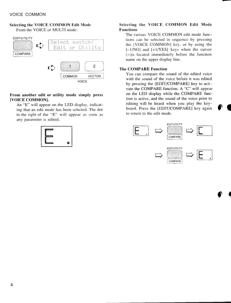
Selecting the ELEMENT TONE Edit Mode
From the VOICE or MULTI mode:
From another edit or utility mode simply press [ELEMENT TONE].
An “E” will appear to the left of the LED display to indicate that an edit mode is selected, and the element selected for editing will be displayed to the right of the display — “A”, “b”, “C”, or “d”. A dot will appear to the right of the element character as soon as any parameter has been edited.
Different elements can be selected for editing by pressing the appropriate [ELEMENT SELECT] key — [A], [B], [C] or [D]. If a 2-element voice is being edited, only elements A and B can be selected.
Any of the available elements can also be turned on or off by pressing the appropriate [ELEMENT ON/OFF] key. Each key alternately turns the associated element on and off, and the on/off status of the elements is shown to the right of the upper LCD line. If the element character is showing, the associated element is
ON, if a dash appears in place of the element character, that element is OFF. The ability to turn elements on or off while editing makes it easier to hear the effect of parameter changes on a single element. The currently selected element is also shown on the LCD as a reversed (white on black) character.
In this example elements A, B and D are ON, while element C is OFF. Element A is currently selected for editing.
ET>WAVE 000 ÅB-D
Piano:Piano
Selecting the ELEMENT TONE Edit Mode Functions
The various ELEMENT TONE edit mode functions can be selected in sequence by pressing the [ELEMENT TONE] key, or by using the [–1/NO] and [+1/YES] keys when the cursor (6)is located immediately before the function name on the upper display line.
The COMPARE Function
You can compare the sound of the edited voice with the sound of the voice before it was edited by pressing the [EDIT/COMPARE] key to activate the COMPARE function. A “ C ” will appear on the LED display while the COMPARE function is active, and the sound of the voice prior to editing will be heard when you play the keyboard. Press the [EDIT/COMPARE] key again to return to the edit mode.
|
|
|
|
16

ELEMENT TONE
WAVE TYPE
ET>WAVE 000 !BCD
Piano:Piano
Summary: Assigns a preset wave to the selected element.
Settings: Elements A and C (AWM): 0 … 127 Elements B and D (FM): 0 … 255
Procedure: Use the [4] and [6] cursor keys to place the underline cursor under the left
AWM WAVEFORM LIST
parameter on the lower display line to directly select the different wave categories, or under the right parameter to select individual waves. Use the [–1/NO] and [+1/YES] keys to select the desired wave (refer to the wave list, below).
Details: The number of waves available depends on whether the currently selected element is an AWM element (A or C) or an FM element (B or D). The SY35 has 128 preset AWM waves (0 … 127) and 256 preset FM waves (0 … 255).
Category |
No. |
Name |
|
Category |
|
No. |
Name |
Category |
No. |
Name |
Category |
No. |
Name |
|
Piano |
0 |
Piano |
|
Bass |
|
32 |
E.Bass 3 |
Synth |
64 |
PopsHit |
OSC |
96 |
Pad wv |
|
|
1 |
E.Piano |
|
|
|
33 |
E.Bass 4 |
|
|
|
|
97 |
Digital1 |
|
|
|
|
|
SFX |
65 |
NoisPad1 |
|
|
||||||
|
2 |
Clavi |
|
|
|
34 |
Slap |
|
98 |
Digital2 |
|
|||
|
|
|
|
|
66 |
NoisPad2 |
|
|
||||||
|
3 |
Cembalo |
|
|
|
35 |
Fretless |
|
|
99 |
Digital3 |
|
||
|
|
|
|
|
67 |
NoisPad3 |
|
|
||||||
|
4 |
Celesta |
|
|
|
36 |
SynBass1 |
|
|
100 |
Digital4 |
|
||
|
|
|
|
|
68 |
Coin |
|
|
||||||
Organ |
5 |
P.Organ |
|
|
|
37 |
SynBass2 |
|
|
101 |
Digital5 |
|
||
|
|
|
|
69 |
Crash |
|
|
|||||||
|
|
|
|
|
|
|
102 |
Saw 1 |
|
|||||
|
6 |
E.Organ1 |
|
Str. |
|
38 |
Strings |
|
70 |
Bottle |
|
|
||
|
7 |
E.Organ2 |
|
|
|
39 |
Vn.Ens. |
|
71 |
BotleOpn |
|
103 |
Saw 2 |
|
|
8 |
Bandneon |
|
|
|
40 |
Cello |
|
72 |
Cracker |
|
104 |
Saw 3 |
|
|
|
|
|
|
|
41 |
Pizz. |
|
73 |
Scratch |
|
105 |
Saw 4 |
|
Brass |
9 |
Trumpet |
|
|
|
|
|
|
||||||
|
|
|
|
|
106 |
Square 1 |
|
|||||||
|
10 |
Mute Trp |
|
|
|
42 |
Syn Str |
|
|
|
|
|
||
|
|
|
|
Hits |
74 |
Metal 1 |
|
107 |
Square 2 |
|
||||
|
11 |
Trombone |
|
|
|
|
|
|
|
|||||
|
|
Vocal |
|
43 |
Choir |
|
75 |
Metal 2 |
|
108 |
Square 3 |
|
||
|
12 |
Flugel |
|
|
|
|
|
|||||||
|
|
|
|
44 |
Itopia |
|
76 |
Metal 3 |
|
109 |
Square 4 |
|
||
|
13 |
Fr Horn |
|
|
|
|
|
|
||||||
|
|
|
|
45 |
Choir pa |
|
77 |
Metal 4 |
|
110 |
Pulse 1 |
|
||
|
14 |
BrasEns |
|
|
|
|
|
|
||||||
|
|
Perc. |
|
46 |
Vibes |
|
78 |
Wood |
|
111 |
Pulse 2 |
|
||
|
15 |
SynBrass |
|
|
|
|
|
|||||||
|
|
|
|
79 |
Bamboo |
|
112 |
Pulse 3 |
|
|||||
|
|
|
|
|
|
47 |
Marimba |
|
|
|
||||
Wood |
16 |
Flute |
|
|
|
|
80 |
Slam |
|
113 |
Pulse 4 |
|
||
|
|
|
48 |
Bells |
|
|
|
|||||||
|
17 |
Clarinet |
|
|
|
|
|
|
|
114 |
Pulse 5 |
|
||
|
|
|
|
49 |
Timpani |
Tran. |
81 |
Tp. Body |
|
|
||||
|
18 |
Oboe |
|
|
|
|
115 |
Pulse 6 |
|
|||||
|
|
|
|
50 |
Tom |
|
82 |
Tb. Body |
|
|
||||
|
19 |
Sax |
|
|
|
|
|
116 |
Tri |
|
||||
|
|
|
|
51 |
E. Tom |
|
83 |
HornBody |
|
|
||||
|
|
|
|
|
|
|
|
117 |
Sin8’ |
|
||||
Gtr |
20 |
Gut |
|
|
|
52 |
Cuica |
|
84 |
Fl. Body |
|
|
||
|
|
|
|
|
118 |
Sin8’+4’ |
|
|||||||
|
21 |
Steel |
|
|
|
53 |
Whistle |
|
85 |
Str.Body |
|
|
||
|
|
|
|
|
|
|
|
|
||||||
|
22 |
E.Gtr 1 |
|
|
|
54 |
ThumbStr |
|
86 |
AirBlown |
SEQ |
119 |
SEQ 1 |
|
|
23 |
E.Gtr 2 |
|
|
|
|
|
|
87 |
Reverse1 |
|
|||
|
|
Synth |
|
55 |
SynPad |
|
|
120 |
SEQ 2 |
|
||||
|
24 |
Mute Gtr |
|
|
|
88 |
Reverse2 |
|
|
|||||
|
|
|
|
56 |
Harmonic |
|
|
121 |
SEQ 3 |
|
||||
|
25 |
Sitar |
|
|
|
|
89 |
Reverse3 |
|
|
||||
|
|
|
|
57 |
SynLead1 |
|
|
122 |
SEQ 4 |
|
||||
|
26 |
Pluck 1 |
|
|
|
|
|
|
|
|
||||
|
|
|
|
58 |
SynLead2 |
OSC |
90 |
EP wv |
|
123 |
SEQ 5 |
|
||
|
27 |
Pluck 2 |
|
|
|
|
|
|||||||
|
|
|
|
59 |
Bell Mix |
|
91 |
Organ wv |
|
124 |
SEQ 6 |
|
||
|
|
|
|
|
|
|
|
|
||||||
Bass |
28 |
Wood B 1 |
|
|
|
60 |
Sweep |
|
92 |
M.Tp wv |
|
125 |
SEQ 7 |
|
|
29 |
Wood B 2 |
|
|
|
61 |
HumanAtk |
|
93 |
Gtr wv |
|
126 |
SEQ 8 |
|
|
30 |
E.Bass 1 |
|
|
|
62 |
Noise 1 |
|
94 |
Str wv 1 |
|
|
|
|
|
|
|
|
|
Drum |
127 |
Drum set |
|
||||||
|
31 |
E.Bass 2 |
|
|
|
63 |
Noise 2 |
|
95 |
Str wv 2 |
|
|||
|
|
|
|
|
|
|
|
|
||||||
|
|
|
|
|
|
|
|
|
|
|
|
|
|
|
AWM Waveform Category Descriptions |
|
|
|
|
|
|
|
|
|
|
|
|||
|
|
|
|
|
|
|||||||||
Piano |
Piano, clavi, and other decay-type keyboard sounds. |
Synth |
A range of synth sounds (including noise). |
|
|
|||||||||
Organ |
Pipe, electric and reed organs. |
|
|
SFX |
Special effects – crash, bottle, etc. |
|
|
|
||||||
Brass |
Acoustic and synthesized brass sounds. |
|
Hits |
Struck metal and woods. |
|
|
|
|
||||||
Wood |
Flute, sax and other woodwind sounds. |
|
|
Tran. |
Transient attack waves and some reverse sounds. |
|
||||||||
Gtr |
Acoustic and electric guitars. |
|
|
OSC |
Standard synth waveforms and the basic waveforms |
|
||||||||
Bass |
Acoustic, electric, and synth bass. |
|
|
|
from some actual instruments. |
|
|
|
||||||
Str. |
Violin ensemble and other strings. |
|
|
SEQ |
Sequences of sampled sounds. |
|
|
|
||||||
Vocal |
Choir and other vocal-type sounds. |
|
|
Drum |
Drum set waves. |
|
|
|
|
|||||
Perc. |
Vibes, timpani, etc. |
|
|
|
|
|
|
|
|
|
|
|
||
|
|
|
|
|
|
|
|
|
|
|
|
|
|
|
17
ELEMENT TONE
FM WAVEFORM LIST
Category |
No. |
Name |
|
Category |
No. |
Name |
Category |
No. |
Name |
|
Category |
No. |
Name |
|
Piano |
0 |
E.Piano1 |
|
Pluck |
49 |
Guitar 4 |
Syn.S |
98 |
Sus. 1 |
|
SFX |
147 |
SFX 5 |
|
|
1 |
E.Piano2 |
|
|
50 |
Guitar 5 |
|
99 |
Sus. 2 |
|
|
148 |
SFX 6 |
|
|
2 |
E.Piano3 |
|
|
51 |
Guitar 6 |
|
100 |
Sus. 3 |
|
|
149 |
SFX 7 |
|
|
3 |
E.Piano4 |
|
|
52 |
Guitar 7 |
|
101 |
Sus. 4 |
|
|
|
|
|
|
|
|
|
|
OSC 1 |
150 |
Sin 16’ |
|
||||||
|
4 |
E.Piano5 |
|
|
53 |
Guitar 8 |
|
102 |
Sus. 5 |
|
|
|||
|
5 |
E.Piano6 |
|
|
|
|
|
103 |
Sus. 6 |
|
|
151 |
Sin 8’ |
|
|
|
Bass. |
54 |
Bass 1 |
|
|
|
|||||||
|
|
|
|
|
104 |
Sus. 7 |
|
|
152 |
Sin 4’ |
|
|||
Organ |
6 |
E.Organ1 |
|
|
55 |
Bass 2 |
|
|
|
|
||||
|
|
|
|
|
153 |
Sin2 2/3 |
|
|||||||
|
|
|
105 |
Sus. 8 |
|
|
|
|||||||
|
7 |
E.Organ2 |
|
|
56 |
Bass 3 |
|
|
|
|
||||
|
|
|
|
|
|
154 |
Sin 2’ |
|
||||||
|
|
|
|
106 |
Sus. 9 |
|
|
|
||||||
|
8 |
E.Organ3 |
|
|
57 |
Bass 4 |
|
|
|
|
||||
|
|
|
|
|
|
155 |
Saw 1 |
|
||||||
|
|
|
|
107 |
Sus. 10 |
|
|
|
||||||
|
9 |
E.Organ4 |
|
|
58 |
Bass 5 |
|
|
|
|
||||
|
|
|
|
|
|
156 |
Saw 2 |
|
||||||
|
|
|
|
108 |
Sus. 11 |
|
|
|
||||||
|
10 |
E.Organ5 |
|
|
59 |
Bass 6 |
|
|
|
|
||||
|
|
|
|
|
|
157 |
Square |
|
||||||
|
|
|
|
109 |
Sus. 12 |
|
|
|
||||||
|
11 |
E.Organ6 |
|
|
60 |
Bass 7 |
|
|
|
|
||||
|
|
|
|
|
|
158 |
LFOnoise |
|
||||||
|
|
|
|
110 |
Sus. 13 |
|
|
|
||||||
|
12 |
E.Organ7 |
|
|
61 |
Bass 8 |
|
|
|
|
||||
|
|
|
|
|
|
159 |
Noise 1 |
|
||||||
|
|
|
|
111 |
Sus. 14 |
|
|
|
||||||
|
13 |
E.Organ8 |
|
|
62 |
Bass 9 |
|
|
|
|
||||
|
|
|
|
|
|
160 |
Noise 2 |
|
||||||
|
|
|
|
112 |
Sus. 15 |
|
|
|
||||||
Brass |
14 |
Brass 1 |
|
Str. |
63 |
Str 1 |
|
|
|
161 |
Digi 1 |
|
||
|
|
113 |
Attack 1 |
|
|
|
||||||||
|
15 |
Brass 2 |
|
|
64 |
Str 2 |
|
114 |
Attack 2 |
|
|
162 |
Digi 2 |
|
|
16 |
Brass 3 |
|
|
65 |
Str 3 |
|
115 |
Attack 3 |
|
|
163 |
Digi 3 |
|
|
17 |
Brass 4 |
|
|
66 |
Str 4 |
|
116 |
Attack 4 |
|
|
164 |
Digi 4 |
|
|
18 |
Brass 5 |
|
|
67 |
Str 5 |
|
117 |
Attack 5 |
|
|
165 |
Digi 5 |
|
|
19 |
Brass 6 |
|
|
68 |
Str 6 |
|
|
|
|
|
166 |
Digi 6 |
|
|
|
|
|
|
|
|
|
|
||||||
|
20 |
Brass 7 |
|
|
69 |
Str 7 |
Syn.M |
118 |
Move 1 |
|
|
167 |
Digi 7 |
|
|
21 |
Brass 8 |
|
|
|
|
|
119 |
Move 2 |
|
|
168 |
Digi 8 |
|
|
|
Perc. |
70 |
Vibes 1 |
|
|
|
|||||||
|
22 |
Brass 9 |
|
|
120 |
Move 3 |
|
|
169 |
Digi 9 |
|
|||
|
23 |
Brass 10 |
|
|
71 |
Vibes 2 |
|
121 |
Move 4 |
|
|
170 |
Digi 10 |
|
|
24 |
Brass 11 |
|
|
72 |
Vibes 3 |
|
122 |
Move 5 |
|
|
171 |
Digi 11 |
|
|
25 |
Brass 12 |
|
|
73 |
Vibes 4 |
|
123 |
Move 6 |
|
|
|
|
|
|
|
|
|
|
OSC 2 |
172 |
wave1-1 |
|
||||||
|
26 |
Brass 13 |
|
|
74 |
Marimba1 |
|
124 |
Move 7 |
|
|
|||
|
27 |
Brass 14 |
|
|
75 |
Marimba2 |
|
|
|
|
|
173 |
wave1-2 |
|
|
|
|
|
|
|
|
|
|
||||||
|
|
|
76 |
Marimba3 |
Syn.D |
125 |
Decay 1 |
|
|
174 |
wave1-3 |
|
||
Wood |
28 |
Wood 1 |
|
|
|
|
|
|||||||
|
|
77 |
Bells 1 |
|
126 |
Decay 2 |
|
|
175 |
wave2-1 |
|
|||
|
29 |
Wood 2 |
|
|
78 |
Bells 2 |
|
127 |
Decay 3 |
|
|
176 |
wave2-2 |
|
|
30 |
Wood 3 |
|
|
79 |
Bells 3 |
|
128 |
Decay 4 |
|
|
177 |
wave2-3 |
|
|
31 |
Wood 4 |
|
|
80 |
Bells 4 |
|
129 |
Decay 5 |
|
|
|
: |
|
|
32 |
Wood 5 |
|
|
81 |
Bells 5 |
|
130 |
Decay 6 |
|
|
|
: |
|
|
33 |
Wood 6 |
|
|
82 |
Bells 6 |
|
131 |
Decay 7 |
|
|
220 |
wave17-1 |
|
|
34 |
Wood 7 |
|
|
83 |
Bells 7 |
|
132 |
Decay 8 |
|
|
221 |
wave17-2 |
|
|
35 |
Wood 8 |
|
|
84 |
Bells 8 |
|
133 |
Decay 9 |
|
|
222 |
wave17-3 |
|
Reed |
36 |
Reed 1 |
|
|
85 |
Metal 1 |
|
134 |
Decay 10 |
|
|
|
|
|
|
|
|
|
OSC 3 |
223 |
wave18-1 |
|
|||||||
|
37 |
Reed 2 |
|
|
86 |
Metal 2 |
|
135 |
Decay 11 |
|
|
|||
|
|
|
|
|
|
224 |
wave18-2 |
|
||||||
|
38 |
Reed 3 |
|
|
87 |
Metal 3 |
|
136 |
Decay 12 |
|
|
|
||
|
|
|
|
|
|
225 |
wave18-3 |
|
||||||
|
39 |
Reed 4 |
|
|
88 |
Metal 4 |
|
137 |
Decay 13 |
|
|
|
||
|
|
|
|
|
|
|
: |
|
||||||
|
40 |
Reed 5 |
|
|
89 |
Metal 5 |
|
138 |
Decay 14 |
|
|
|
|
|
|
|
|
|
|
|
|
: |
|
||||||
|
41 |
Reed 6 |
|
|
90 |
Metal 6 |
|
139 |
Decay 15 |
|
|
|
|
|
|
|
|
|
|
|
250 |
wave27-1 |
|
||||||
|
|
|
|
|
|
|
|
140 |
Decay 16 |
|
|
|
||
Pluck |
42 |
Clavi 1 |
|
Syn.S |
91 |
Lead 1 |
|
|
|
251 |
wave27-2 |
|
||
|
|
141 |
Decay 17 |
|
|
|
||||||||
|
43 |
Clavi 2 |
|
|
92 |
Lead 2 |
|
142 |
Decay 18 |
|
|
252 |
wave27-3 |
|
|
44 |
Clavi 3 |
|
|
93 |
Lead 3 |
|
|
|
|
|
253 |
wave28 |
|
|
|
|
|
|
|
|
|
|
||||||
|
45 |
Clavi 4 |
|
|
94 |
Lead 4 |
SFX |
143 |
SFX 1 |
|
|
254 |
wave29 |
|
|
46 |
Guitar 1 |
|
|
95 |
Lead 5 |
|
144 |
SFX 2 |
|
|
255 |
wave30 |
|
|
47 |
Guitar 2 |
|
|
96 |
Lead 6 |
|
145 |
SFX 3 |
|
|
|
|
|
|
48 |
Guitar 3 |
|
|
97 |
Lead 7 |
|
146 |
SFX 4 |
|
|
|
|
|
FM Voice Category Descriptions |
|
|
|
|
|
|
|
|
|
|
|
|||
|
|
|
|
|
|
|
|
|||||||
Piano |
Electric pianos. |
|
|
|
Perc. |
Vibes, marimba, bells and other percussion sounds. |
|
|||||||
Organ |
Electric organs. |
|
|
|
Syn.S |
Sustained lead synth sounds. |
|
|
|
|||||
Brass |
A variety of brass sounds. |
|
|
|
Syn.M |
Synth sounds that vary with time. |
|
|
|
|||||
Wood |
Woodwind instrument sounds. |
|
|
Syn.D |
Decay-type synth sounds. |
|
|
|
|
|||||
Reed |
Sax, oboe and other reed instruments. |
|
|
SFX |
A range of sound-effect type synth sounds. |
|
|
|||||||
Pluck |
Guitar, clavi, and other plucked instrument sounds. |
OSC1 |
Sine, sawtooth, and other standard synth waveforms. |
|
||||||||||
Bass |
Bass sounds. |
|
|
|
OSC2 |
Basic FM timbres, group 1. |
|
|
|
|||||
Str. |
Strings. |
|
|
|
OSC3 |
Basic FM timbres, group 2. |
|
|
|
|||||
|
|
|
|
|
|
|
|
|
|
|
|
|
|
|
If the TYPE parameter in the ELEMENT ENVELOPE edit mode (page 27) is set to PRESET, selecting a WAVE TYPE also selects
the corresponding preset envelope. If a different envelope type is selected, the preset envelope is not selected together with the wave.
18
ELEMENT TONE
ELEMENT COPY
ET>COPYfrom ABCD
any Voice? ->
Summary: Copies all element parameters from an element of the same type (AWM or FM) in another voice to the current element of the current voice.
Settings: Source: I, C, P
Bank: 1 … 8
Number: 1 … 8
Element: A/C or B/D
Procedure: Use the [4] and [6] cursor keys to move the cursor to the source, bank, or number of the source voice (the voice from which the element parameters are to be copied) to the left of the lower display line. Use the [–1/NO] and [+1/YES] keys to set the selected parameter as necessary.
Next move the cursor to the element type parameter to the right of the lower display line, and select the element from which the data is to be copied using the [–1/NO] and [+1/YES] keys.
Press the [6] cursor key one more time and the “Are you sure?” display will appear. Press [+1/YES] to execute the element copy operation or [–1/NO] to cancel. “>>Completed!!<<” will appear briefly when the copy operation has finished.
Details: In this display the source, bank and number parameters are shown in the standard SY35 voice number format. “P12,” for example, is preset bank 1, number 2; “I35” is internal bank 3, number 5, etc.
Data can only be copied between elements of the same type. If the element currently being edited is an AWM element (A or C), only element A or C of the source voice can be copied from. the same applies to FM elements.
The data for all parameters contained in the ELEMENT TONE mode will be copied.
FREQUENCY SHIFT
ET>FREQ. ABCD
Shift= 0
Summary: Shifts the frequency (pitch) of the selected element up or down in semitone steps.
Settings: –12 ... 0 … +12.
Procedure: Use the [6] key to move the cursor to the lower display line. Use the [–1/NO] and [+1/YES] keys to select the desired amount of frequency shift.
Details: A setting of “–12,” for example, shifts the pitch of the selected element down by one octave; a setting of “+4” shifts the pitch up by a major third.
The Frequency Shift function can be used to transpose an element to its most useful range, or to create harmony (intervals) between different elements.
19
ELEMENT TONE
VOLUME
ET>VOLUME ABCD
Level= 0
Summary: Adjusts the volume of the selected element.
Settings: 0 ... 99
Procedure: Use the [6] key to move the cursor to the lower display line. Use the [–1/NO] and [+1/YES] keys to select the desired volume level.
Details: A setting of “0” produces no sound while a setting of “99” produces maximum volume. The ability to independently adjust the volume of each element makes it simple to set up the optimum balance or “mix” between elements.
PAN
ET>PAN ÅBCD
L--|--R
Summary: Determines the position in the stereo sound field in which the sound from selected element will be heard (left to right).
Settings: Graphic Display: L--+--R, 5 positions from left to right.
Procedure: Use the [6] key to move the cursor to the lower display line. Use the [–1/NO] and [+1/YES] keys to select the desired pan position.
Details: The lower line of the display shows a graphic representation of the stereo sound field with “L” representing “left” and “R” representing “right.” As you edit the pan parameter the position indicator will appear at the corresponding position on the graphic display. A total of five different positions are available, corresponding to left, left-center, center, rightcenter, and right.
Interesting stereo effects can be produced by placing the output from different elements at different locations in the stereo sound field.
VELOCITY SENSITIVITY
ET>VELOCITY ABCD
Sense= 0 ---
Summary: Determines how the output level of the selected element changes in response to velocity changes (keyboard initial touch response).
Settings: –5 ... 0 … +5
Procedure: Use the [6] key to move the cursor to the lower display line. Use the [–1/NO] and [+1/YES] keys to select the desired velocity sensitivity.
Details: Plus “+” settings produce higher output level in response to higher velocity values — i.e. the harder a key is played, the louder the sound. Minus “–” settings produce the opposite effect: lower level in response to higher velocity. A setting of “0” results in no level variation.
0 No response.
+1 Narrow change between medium-hard and hard velocity.
20
 Loading...