


U
RX-V1065
AV Receiver
OWNER’S MANUAL
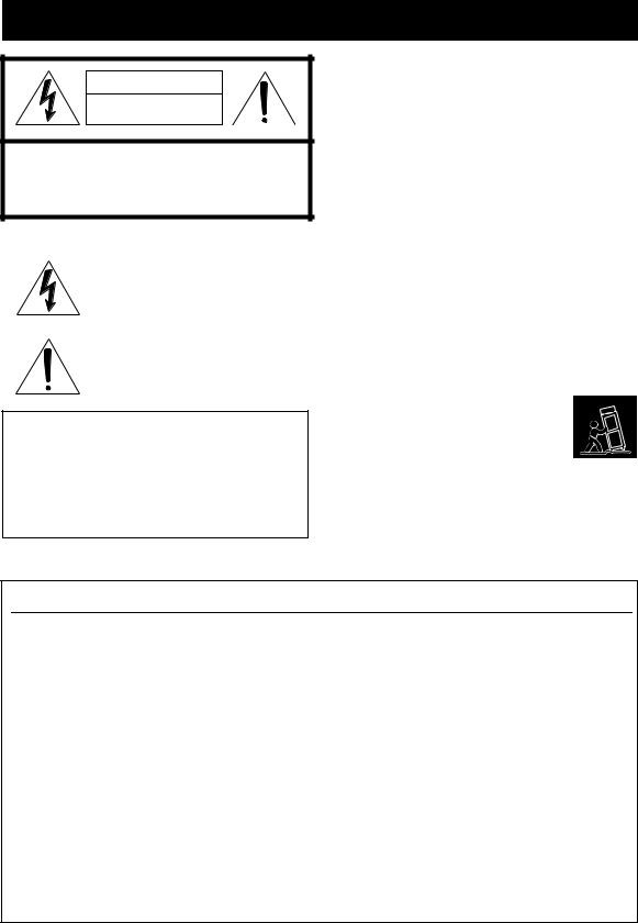
IMPORTANT SAFETY INSTRUCTIONS
CAUTION |
RISK OF ELECTRIC SHOCK |
DO NOT OPEN |
CAUTION: TO REDUCE THE RISK OF |
ELECTRIC SHOCK, DO NOT REMOVE |
COVER (OR BACK). NO USER-SERVICEABLE |
PARTS INSIDE. REFER SERVICING TO |
QUALIFIED SERVICE PERSONNEL. |
•Explanation of Graphical Symbols
The lightning flash with arrowhead symbol, within an equilateral triangle, is intended to alert you to the presence of uninsulated “dangerous voltage” within the product’s enclosure that may be of sufficient magnitude to constitute a risk of electric shock to persons.
The exclamation point within an equilateral triangle is intended to alert you to the presence of important operating and maintenance (servicing) instructions in the literature accompanying the appliance.
Note to CATV system installer:
This reminder is provided to call the CATV system installer’s attention to Article 820-40 of the NEC that provides guidelines for proper grounding and, in particular, specifies that the cable ground shall be connected to the grounding system of the building, as close to the point of cable entry as practical.
1Read these instructions.
2Keep these instructions.
3Heed all warnings.
4Follow all instructions.
5Do not use this apparatus near water.
6Clean only with dry cloth.
7Do not block any ventilation openings. Install in accordance with the manufacturer’s instructions.
8Do not install near any heat sources such as radiators, heat registers, stoves, or other apparatus (including amplifiers) that produce heat.
9Do not defeat the safety purpose of the polarized or grounding-type plug. A polarized plug has two blades with one wider than the other. A grounding type plug has two blades and a third grounding prong. The wide blade or the third prong are provided for your safety. If the provided plug does not fit into your outlet, consult an electrician for replacement of the obsolete outlet.
10Protect the power cord from being walked on or pinched particularly at plugs, convenience receptacles, and the point where they exit from the apparatus.
11Only use attachments/accessories specified by the manufacturer.
12Use only with the cart, stand, tripod, bracket, or table specified by the manufacturer, or sold
with the apparatus. When a cart is used, use caution when moving the cart/apparatus combination to avoid injury from tip-over.
13Unplug this apparatus during lightning storms or when unused for long periods of time.
14Refer all servicing to qualified service personnel. Servicing is required when the apparatus has been damaged in any way, such as power-supply cord or plug is damaged, liquid has been spilled or objects have fallen into the apparatus, the apparatus has been exposed to rain or moisture, does not operate normally, or has been dropped.
FCC INFORMATION (for US customers)
1IMPORTANT NOTICE: DO NOT MODIFY THIS UNIT!
This product, when installed as indicated in the instructions contained in this manual, meets FCC requirements. Modifications not expressly approved by Yamaha may void your authority, granted by the FCC, to use the product.
2IMPORTANT: When connecting this product to accessories and/or another product use only high quality shielded cables. Cable/s supplied with this product MUST be used. Follow all installation instructions. Failure to follow instructions could void your FCC authorization to use this product in the USA.
3NOTE: This product has been tested and found to comply with the requirements listed in FCC Regulations, Part 15 for Class “B” digital devices. Compliance with these requirements provides a reasonable level of assurance that your use of this product in a residential environment will not result in harmful interference with other electronic devices.
This equipment generates/uses radio frequencies and, if not installed and used according to the instructions found in the users manual, may cause interference harmful to the operation of other electronic devices.
Compliance with FCC regulations does not guarantee that interference will not occur in all installations. If this product is found to be the source of interference, which can be determined by turning the unit “OFF” and “ON”, please try to eliminate the problem by using one of the following measures:
Relocate either this product or the device that is being affected by the interference.
Utilize power outlets that are on different branch (circuit breaker or fuse) circuits or install AC line filter/s.
In the case of radio or TV interference, relocate/reorient the antenna. If the antenna lead-in is 300 ohm ribbon lead, change the lead-in to coaxial type cable.
If these corrective measures do not produce satisfactory results, please contact the local retailer authorized to distribute this type of product. If you can not locate the appropriate retailer, please contact Yamaha Electronics Corp., U.S.A. 6660 Orangethorpe Ave, Buena Park, CA 90620.
The above statements apply ONLY to those products distributed by Yamaha Corporation of America or its subsidiaries.
Caution-i En

Caution: Read this before operating your unit.
1To assure the finest performance, please read this manual carefully. Keep it in a safe place for future reference.
2Install this sound system in a well ventilated, cool, dry, clean place – away from direct sunlight, heat sources, vibration, dust, moisture, and/or cold. Allow ventilation space of at least 30 cm on the top, 20 cm on the left and right, and 20 cm on the back of this unit.
3Locate this unit away from other electrical appliances, motors, or transformers to avoid humming sounds.
4Do not expose this unit to sudden temperature changes from cold to hot, and do not locate this unit in an environment with high humidity (i.e. a room with a humidifier) to prevent condensation inside this unit, which may cause an electrical shock, fire, damage to this unit, and/or personal injury.
5Avoid installing this unit where foreign objects may fall onto this unit and/or this unit may be exposed to liquid dripping or splashing. On the top of this unit, do not place:
–Other components, as they may cause damage and/or discoloration on the surface of this unit.
–Burning objects (i.e. candles), as they may cause fire, damage to this unit, and/or personal injury.
–Containers with liquid in them, as they may fall and liquid may cause electrical shock to the user and/or damage to this unit.
6Do not cover this unit with a newspaper, tablecloth, curtain, etc. in order not to obstruct heat radiation. If the temperature inside this unit rises, it may cause fire, damage to this unit, and/or personal injury.
7Do not plug in this unit to a wall outlet until all connections are complete.
8Do not operate this unit upside-down. It may overheat, possibly causing damage.
9Do not use force on switches, knobs and/or cords.
10When disconnecting the power cable from the wall outlet, grasp the plug; do not pull the cable.
11Do not clean this unit with chemical solvents; this might damage the finish. Use a clean, dry cloth.
12Only voltage specified on this unit must be used. Using this unit with a higher voltage than specified is dangerous and may cause fire, damage to this unit, and/or personal injury. Yamaha will not be held responsible for any damage resulting from use of this unit with a voltage other than specified.
13To prevent damage by lightning, keep the power cord and outdoor antennas disconnected from a wall outlet or the unit during a lightning storm.
14Do not attempt to modify or fix this unit. Contact qualified Yamaha service personnel when any service is needed. The cabinet should never be opened for any reasons.
15When not planning to use this unit for long periods of time (i.e. vacation), disconnect the AC power plug from the wall outlet.
16Install this unit near the AC outlet and where the AC power plug can be reached easily.
17Be sure to read the “Troubleshooting” section on common operating errors before concluding that this unit is faulty.
18Before moving this unit, press KMAIN ZONE ON/OFF to set this unit to the standby mode, and disconnect the AC power plug from the wall outlet in the main room.
19VOLTAGE SELECTOR (Asia and General models only) The VOLTAGE SELECTOR on the rear panel of this unit must be set for your local main voltage BEFORE plugging into the AC wall outlet. Voltages are:
..... AC 110/120/220/230-240 V, 50/60 Hz (General model)
.........................AC 220/230-240 V, 50/60 Hz (Asia model)
20The batteries shall not be exposed to excessive heat such as sunshine, fire or like.
21Excessive sound pressure from earphones and headphones can cause hearing loss.
22When replacing the batteries, be sure to use batteries of the same type. Danger of explosion may happen if batteries are incorrectly replaced.
WARNING
TO REDUCE THE RISK OF FIRE OR ELECTRIC SHOCK, DO NOT EXPOSE THIS UNIT TO RAIN OR MOISTURE.
As long as this unit is connected to the AC wall outlet, it is not disconnected from the AC power source even if you turn off this unit by KMAIN ZONE ON/OFF. In this state, this unit is designed to consume a very small quantity of power.
FOR CANADIAN CUSTOMERS
To prevent electric shock, match wide blade of plug to wide slot and fully insert.
This Class B digital apparatus complies with Canadian ICES-003.
POUR LES CONSOMMATEURS CANADIENS
Pour éviter les chocs électriques, introduire la lame la plus large de la fiche dans la borne correspondante de la prise et pousser jusqu’au fond.
Cet appareil numérique de la classe B est conforme à la norme NMB-003 du Canada.
IMPORTANT
Please record the serial number of this unit in the space below.
MODEL:
Serial No.:
The serial number is located on the rear of the unit. Retain this Owner’s Manual in a safe place for future reference.
Caution-ii En

Contents
INTRODUCTION |
|
Features.................................................................... |
2 |
About this manual................................................... |
3 |
Supplied accessories................................................ |
3 |
Part names and functions....................................... |
4 |
Front panel ................................................................. |
4 |
Rear panel .................................................................. |
5 |
Front panel display..................................................... |
6 |
Remote control........................................................... |
7 |
Quick start guide..................................................... |
8 |
PREPARATION |
|
Preparing remote control....................................... |
9 |
Installing batteries in the remote control ................... |
9 |
Using the remote control............................................ |
9 |
Connections ........................................................... |
10 |
Placing speakers....................................................... |
10 |
Connecting speakers ................................................ |
11 |
Information on jacks and cable plugs ...................... |
13 |
Connecting a TV monitor or projector .................... |
14 |
Connecting other components ................................. |
15 |
Connecting a Yamaha iPod universal dock or |
|
Bluetooth™ wireless audio receiver.................... |
17 |
Connecting a USB storage device ........................... |
17 |
Using the VIDEO AUX jacks.................................. |
17 |
Connecting the FM and AM antennas ..................... |
18 |
Connecting the power cable..................................... |
18 |
Turning this unit on and off ..................................... |
18 |
Optimizing the speaker setting for your |
|
listening room (YPAO)..................................... |
19 |
Using Auto Setup..................................................... |
19 |
When an error message is displayed during |
|
measurement........................................................ |
21 |
When a warning message is displayed after |
|
measurement........................................................ |
21 |
BASIC OPERATION |
|
Playback................................................................. |
22 |
Basic procedure........................................................ |
22 |
Using the SCENE function ...................................... |
22 |
Selecting an input source on the GUI screen........... |
23 |
Muting audio output................................................. |
23 |
Adjusting high/low frequency sounds |
|
(tone control) ....................................................... |
23 |
Enjoying pure hi-fi sound ........................................ |
23 |
Using your headphones............................................ |
24 |
Displaying input signal information ........................ |
24 |
Changing information on the front panel display .... |
24 |
Enjoying the sound field programs ..................... |
25 |
Selecting sound field programs................................ |
25 |
Enjoying unprocessed input sources |
|
(Straight decode mode)........................................ |
28 |
Enjoying sound field programs without surround |
|
speakers (Virtual CINEMA DSP) ....................... |
28 |
Enjoy sound field programs with headphones |
|
(SILENT CINEMA™) ........................................ |
28 |
Using CINEMA DSP 3D mode ............................... |
28 |
FM/AM tuning ...................................................... |
29 |
Tuning in to the desired FM/AM station |
|
(Frequency tuning) .............................................. |
29 |
Registering FM/AM stations and tuning in |
|
(Preset tuning)...................................................... |
29 |
Using HD Radio™ features |
|
(U.S.A. model only) ........................................... |
31 |
Selecting HD Radio™ audio programs ................... |
31 |
Using the iTunes Tagging feature............................ |
31 |
Displaying HD Radio™ information....................... |
32 |
XM® Satellite Radio tuning |
|
(U.S.A. model only) ........................................... |
33 |
Connecting XM Mini-Tuner Home Dock ............... |
33 |
Activating XM Satellite Radio ................................ |
33 |
XM Satellite Radio® operations ............................. |
34 |
Registering XM Satellite Radio channels................ |
35 |
Displaying the XM Satellite Radio™ information .. |
36 |
SIRIUS Satellite Radio™ tuning |
|
(U.S.A. model only)........................................... |
37 |
Connecting the SiriusConnect™ tuner .................... |
37 |
Activating SIRIUS Satellite Radio™ |
|
subscription.......................................................... |
37 |
SIRIUS Satellite Radio™ operations...................... |
37 |
Registering SIRIUS Satellite Radio™ channels..... |
39 |
Setting the Parental Lock......................................... |
40 |
Displaying the SIRIUS Satellite Radio™ |
|
information .......................................................... |
41 |
Using iPod™.......................................................... |
42 |
Controlling iPod™................................................... |
42 |
Using Bluetooth™ components ........................... |
44 |
Pairing the Bluetooth™ wireless audio receiver |
|
and your Bluetooth component............................ |
44 |
Playback of the Bluetooth™ component ................. |
44 |
Using USB storage devices................................... |
45 |
Playback of the USB storage device........................ |
45 |
Other functions ..................................................... |
46 |
Using the sleep timer ............................................... |
46 |
Using the HDMI™ control function........................ |
46 |
ADVANCED OPERATION |
|
Setting the option menu for each input source |
|
(Option menu)................................................... |
47 |
Option menu items................................................... |
47 |
Selecting a video signal to be output during a |
|
multi-channel audio reproduction........................ |
49 |
Editing surround decoders/sound field |
|
programs ........................................................... |
50 |
Setting sound field parameters................................. |
50 |
Sound field parameters ............................................ |
50 |
Operating various settings for this unit |
|
(Setup menu) ..................................................... |
54 |
Basic operation of the Setup menu .......................... |
55 |
Speaker Setup .......................................................... |
55 |
Sound Setup ............................................................. |
57 |
Function Setup ......................................................... |
58 |
DSP Parameter......................................................... |
60 |
Memory Guard......................................................... |
60 |
Using multi-zone configuration........................... |
61 |
Connecting Zone2.................................................... |
61 |
Controlling Zone2.................................................... |
62 |
Controlling other components with the remote |
|
control................................................................ |
63 |
Setting remote control codes.................................... |
63 |
Resetting all remote control codes........................... |
63 |
Advanced setup..................................................... |
64 |
APPENDIX |
|
Troubleshooting.................................................... |
66 |
Glossary................................................................. |
77 |
Sound field program information ....................... |
80 |
Information on HDMI™...................................... |
81 |
Specifications......................................................... |
82 |
Index ...................................................................... |
83 |
(at the end of this manual) |
|
List of remote control codes................................... |
i |
INTRODUCTION
English
1 En

INTRODUCTION
Features
■Built-in 7-channel power amplifier
•Minimum RMS Output Power (20 Hz to 20 kHz, 0.08% THD, 8 Ω)
•FRONT L/R: 105 W + 105 W
•CENTER: 105 W
•SURROUND L/R: 105 W + 105 W
•SURROUND BACK L/R: 105 W + 105 W
■Speaker/Preout outputs
•Speaker terminals (7-channel), extra speaker terminals (2-channel for presence or Zone2), preout jacks (7.1- channel)
■Input/Output terminals
Input terminals
•HDMI input x 4
•Audio/Visual input
[Audio] Digital input (coaxial) x 2, digital input (optical) x 2, analog input x 2
[Video] Component video x 2, Video x 4
•Audio input (analog) x 2
•Phono input (analog) x 1
•Multi-channel audio input (7.1-channel)
•V-AUX input
[Audio] Analog x 1
[Video] Video x 1
•DOCK terminal to connect a Yamaha iPod universal dock (such as YDS-11, sold separately) or Bluetooth wireless audio receiver (such as YBA-10, sold separately)
•USB port to connect a USB storage device
Output terminals
•Monitor output [Audio/Video] HDMI x 1
[Video] Component video x 1, Video x 1
•Audio/Visual output
[Audio] Analog x 1
[Video] Video x 1
•Audio output Analog x 1
•Zone2 output Analog x 1
Other terminals
Remote input x 1, Remote output x 1
Trigger output x 1
■Proprietary Yamaha technology for the creation of sound fields
•CINEMA DSP 3D
•Compressed Music Enhancer mode
•Virtual CINEMA DSP
•SILENT CINEMA
■Digital audio decoders
• Dolby TrueHD, Dolby Digital Plus decoder
•DTS-HD Master Audio, DTS-HD High Resolution Audio, DTS Express
•Dolby Digital/Dolby Digital EX decoder
•DTS, DTS 96/24 decoder, DTS-ES Matrix 6.1, DTS-ES Discrete 6.1
•Dolby Pro Logic/Dolby Pro Logic II/Dolby Pro Logic IIx decoder
•DSD decoder
•DTS NEO:6 decoder
•Neural Surround decoder (U.S.A. model only)
■Radio tuners
•FM/AM tuning capability
•HD Radio digital broadcast reception capability (U.S.A. model only)
•XM Satellite Radio tuning capability, using XM MiniTuner and Home Dock, sold separately (U.S.A. model only)
•SIRIUS Satellite Radio tuning capability, using SiriusConnect tuner, sold separately (U.S.A. model only)
■ HDMI™ (High-Definition Multimedia Interface)
•HDMI interface for standard, enhanced or highdefinition video as well as multi-channel digital audio.
–Automatic audio and video synchronization (lip sync) information capability
–Deep Color video signal (30/36 bit) transmission capability
–“x.v.Color” video signal transmission capability
–High refresh rate and high resolution video signals capability
–High definition digital audio format signals capability
•Analog to analog and HDMI digital video upconversion (video ↔ component video → HDMI) capability for monitor out
•Analog video input up-scaling for HDMI digital video output 480i(576i) or 480p(576p) → 720p, 1080i or 1080p
•HDMI control function supported
■Automatic speaker setup features
•“YPAO” (Yamaha Parametric Room Acoustic Optimizer) for automatically optimizing speaker outputs suitable for listening environments.
■Other features
•192-kHz/24-bit D/A converter
•GUI (graphic user interface) menus to optimize this unit to suit individual audiovisual system
•iPod and USB file browsing and album art display capability
•Pure Direct mode for pure hi-fi sound for all sources
•Adaptive dynamic range controlling capability
•SCENE function for changing input sources and sound field programs with one key
•Bi-amplification connection capability
•Sleep timer
•Multi-zone function
•iTunes Tagging function (U.S.A. model only)
2 En

|
About this manual |
|
|
|
|
|
|
• |
Some operations can be performed by using either the keys on the front panel or the ones on the remote control. In case the key names differ between |
|
|
|
the front panel and the remote control, the key name on the remote control is given in parentheses. |
|
|
• |
This manual is printed prior to production. Design and specifications are subject to change in part as a result of improvements, etc. In case of |
|
INTRODUCTION |
|
differences between the manual and product, the product has priority. |
|
|
|
|
|
|
• |
For better viewing, we increase the size of characters used in example screen images in this manual. Therefore the size ratio of characters to other |
|
|
|
objects (such as icons) may be different from that of the actual display image. |
|
|
• |
“KMAIN ZONE ON/OFF” or “dHDMI 1” (example) indicates the name of the parts on the front panel or the remote control. Refer to the |
|
|
|
attached sheet or “Part names and functions” (page 4).for the information about each position of the parts. |
|
|
• |
indicates the page describing the related information. |
|
|
• |
yindicates a tip for your operation. |
|
|
|
|
|
|
|
|
|
|
Manufactured under license from Dolby Laboratories.
Dolby, Pro Logic and the double-D symbol are trademarks of Dolby Laboratories
“HDMI”, the “HDMI” logo and “High-Definition Multimedia Interface” are trademarks, or registered trademarks of HDMI Licensing LLC.
Manufactured under license under U.S. Patent No’s: 5,451,942;5,956,674;5,974,380;5,978,762;6,226,616;6,487,535 & other U.S. and worldwide patents issued & pending. DTS is a registered trademark and the DTS logos, Symbol, DTS-HD and DTSHD Master Audio are trademark of DTS, Inc. © 1996-2007 DTS, Inc. All Rights Reserved.
Neural Surround™ name and related logos are trademarks owned by Neural Audio Corporation.
iPod™
“iPod” is a trademark of Apple Inc., registered in the U.S. and other
countries.
Bluetooth™
Bluetooth is a registered trademark of Bluetooth SIG and is used by
Yamaha in accordance with a license agreement.
x.v.Color
“x.v.Color” is a trademark of Sony Corporation.
“SILENT CINEMA” is a trademark of Yamaha Corporation.
SIRIUS, XM and all related marks and logos are trademarks of Sirius XM Radio Inc. and its subsidiaries. All rights reserved. Service not
available in Alaska and Hawaii.
HD Radio™ Technology Manufactured Under License From iBiquity Digital Corp. U.S. and Foreign Patents. HD Radio™ and the HD Radio logo are proprietary trademarks of iBiquity Digital Corp.
Supplied accessories
Check that you received all of the following parts.
•Remote control (page 7)
•Batteries (2) (AAA, R03, UM-4) (page 9)
•Optimizer microphone (page 19)
•AM loop antenna (page 18)
•Indoor FM antenna (page 18)
English
3 En
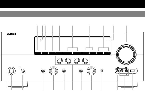
Part names and functions
Front panel
A BC D E |
F |
G |
H I |
J |
|
HDMI THROUGH |
|
|
|
|
|
|
|
|
|
|
|
|
|
|
|
|
|
|
|
|
VOLUME |
|
ZONE2 |
ZONE2 |
|
|
|
|
|
FM |
AM |
|
|
|
ON/OFF |
CONTROL |
INFO |
MEMORY |
l |
PRESET |
h |
l |
CATEGORY h |
l TUNING/CH h |
|
|
|
|
|
|
|
SCENE |
|
|
|
|
|
|
|
|
|
BD/DVD |
TV |
|
CD |
RADIO |
|
|
|
|
MAIN ZONE |
|
PROGRAM |
|
|
|
|
|
INPUT |
|
|
|
|
|
|
|
|
|
|
|
|
|
|
|
PHONES |
TONE CONTROL |
|
|
STRAIGHT |
|
|
PURE DIRECT |
|
OPTIMIZER MIC |
VIDEO AUX |
USB |
|
|
|
|
|
|
|
|||||
ON/OFF |
|
|
|
|
|
|
|
|
|
|
|
SILENT CINEMA |
|
|
|
EFFECT |
|
|
|
|
VIDEO |
AUDIO |
|
|
|
|
|
|
|
|
|
|
|
K L M N O P Q R S T U V
AZONE2 ON/OFF
Switches the zone function on and off (page 62).
BHDMI THROUGH
Lights up in the following cases while this unit is on standby.
•when the HDMI control function is on
•when the HDMI signal standby-through function is currently working
CZONE2 CONTROL
Enables operation of a receiver set in Zone2, including input source switching, volume control and tuner operation, with the main amplifier or remote control after this key is pressed (page 62).
DINFO
Changes information (input, DSP program, audio decoder, etc) displayed on the front panel display (page 24).
EMEMORY
Registers FM/AM stations as preset stations (page 30) or XM/ SIRIUS channels as preset channels (pages 35 and 39).
FPRESET l/ h
Selects an FM/AM preset station (page 30) or an XM/SIRIUS preset channel (pages 35 and 39).
GFM/AM (CATEGORY l/ h)
Change the tuner bands between FM and AM. Select a channel category for a XM/SIRIUS.
HTUNING/CH l/ h
Changes FM/AM frequencies or XM/SIRIUS tuner channels.
IFront panel display
Displays information on this unit (page 6).
JVOLUME control
Controls the volume of this unit (page 22).
KMAIN ZONE ON/OFF
Turns this unit on and off (page 18).
LPHONES jack
For plugging headphones (page 24).
MTONE CONTROL
Adjusts high-frequency/low-frequency output of speakers (page 23).
NPROGRAM selector
Changes sound field programs (page 25).
OSTRAIGHT
Toggles between the selected sound field program and straight decode mode (page 28).
PSCENE
Switches between linked sets of input sources and sound field programs (page 22).
QPURE DIRECT
Changes mode to Pure Direct mode (page 23). This key lights up when Pure Direct mode is on.
RINPUT selector
Selects an input source (page 22).
SOPTIMIZER MIC jack
For connecting the supplied optimizer microphone and adjusting output characteristics of speakers (page 19).
TVIDEO (VIDEO AUX) jack
For connecting the video output cable of a camcorder or game console (page 17).
UAUDIO L/R (VIDEO AUX) jack
For connecting the audio output cable of a camcorder or game console (page 17).
VUSB port
For connecting a USB memory device or USB portable audio player (page 17)
4 En

Part names and functions
Rear panel
a |
b c d e |
|
|
f |
|
|
g |
|
h |
i |
||
SIRIUS |
DOCK |
XM |
HDMI OUT |
HDMI 1 |
HDMI 2 |
HDMI 3 |
HDMI 4 |
ANTENNA |
GND |
AM |
|
|
|
|
|
|
(BD/DVD) |
|
|
|
HD Radio FM |
|
|
||
|
|
|
|
|
|
|
|
UNBAL. |
|
|
|
|
|
|
PHONO |
|
MONITOR OUT |
|
|
SPEAKERS |
|
EXTRA SP ZONE2/PRESENCE |
|
||
|
|
|
|
|
|
SINGLE |
CLASS 2 WIRING |
|
||||
|
COMPONENT |
|
|
COMPONENT |
|
|
|
|
|
|
||
|
VIDEO |
|
|
VIDEO |
|
REMOTE |
|
|
|
|
|
|
|
|
|
|
|
|
|
|
|
|
|
|
|
PR |
|
|
|
|
|
|
|
PR |
|
IN |
|
|
|
|
|
|
|
|
|
|
|
GND |
|
|
|
|
|
|
OUT |
|
|
|
|
|
|
|
|
PB |
|
|
|
|
|
|
|
PB |
VIDEO |
|
|
|
|
|
|
|
|
|
|
|
VIDEO |
|
|
|
|
|
|
|
|
|
|
|
|
|
|
|
|
Y |
|
|
|
|
|
|
|
Y |
|
|
12V |
|
|
|
|
|
|
|
|
|
|
|
|
|
|
|
|
|
|
|
|
|
|
|
SURROUND BACK/ |
||
|
|
|
|
|
|
|
|
|
|
0.1A MAX. |
FRONT |
CENTER |
SURROUND |
|
||||
|
|
|
|
|
|
|
|
|
|
|
BI-AMP |
|
||||||
|
|
|
|
|
|
|
|
|
|
TRIGGER OUT |
|
|
|
|
|
|
|
|
|
|
|
|
|
|
|
|
|
|
|
|
CENTER |
|
|
|
SINGLE |
CENTER |
|
OPTICAL |
COAXIAL |
COAXIAL |
OPTICAL |
|
|
|
|
|
FRONT |
SURROUND |
SUR.BACK |
SUBWOOFER |
|
FRONT |
SURROUND |
SUR. BACK |
1 SUBWOOFER |
2 |
( TV ) |
|
(CD) |
|
|
|
AV |
|
|
ZONE2 |
|||||||||
|
|
|
|
|
|
|
MULTI CH INPUT |
AUDIO |
|
|
PRE OUT |
|
|
|||||
AV 1 |
AV 2 |
AV 3 |
AV 4 |
AV 5 |
AV 6 |
OUT |
AUDIO1 |
AUDIO2 |
|
OUT |
OUT |
|
|
|
|
|||
|
j |
k l |
m |
n o |
p |
|
a |
SIRIUS jack |
|
|
k |
AV OUT jacks |
|
|
For connecting a SiriusConnect tuner (sold separately) |
|
|
Outputs audio/visual signals from a selected analog input source |
||
|
(page 37). |
|
|
|
to an external component (page 15). |
|
b |
DOCK terminal |
|
|
l |
AUDIO 1/2 jacks |
|
|
For connecting an optional Yamaha iPod universal dock (YDS- |
|
For connecting external components for audio inputs 1-2 |
|||
|
11) or Bluetooth wireless audio receiver (YBA-10) (page 17). |
|
(page 15). |
|
||
c |
XM jack |
|
|
m MULTI CH INPUT jacks |
||
|
For connecting XM Mini-Tuner in XM Mini-Tuner Home Dock |
|
For connecting a player that supports a multi-channel output |
|||
|
(sold separately) (page 33). |
|
|
|
(page 16). |
|
d |
PHONO jacks |
|
|
n |
AUDIO OUT jacks |
|
|
For connecting a turntable (page 15). |
|
|
Outputs audio signals from a selected analog input source to an |
||
e |
MONITOR OUT jacks |
|
|
|
external component (page 15). |
|
|
Outputs visual signals from this unit to a video monitor, such as |
o |
ZONE2 OUT jacks |
|||
|
a TV (page 14). |
|
|
|
Outputs sound of this unit to an external amplifier set in a |
|
|
REMOTE IN/OUT jacks |
|
|
|
different zone (page 61). |
|
|
For connecting an external component that supports the remote |
p |
PRE OUT jacks |
|||
|
control function (page 17). |
|
|
|
Outputs multi-channel signals from up to 7.1 channels to an |
|
|
TRIGGER OUT jack |
|
|
|
external amplifier (page 16). |
|
For connecting an external terminal with a trigger input terminal to operate it linked with operation of this unit. For example, when an electric screen that supports a trigger input is connected, it opens and closes linked with operation of an input source selected in this unit.
fHDMI OUT/HDMI 1-4 jacks
For connecting an HDMI-compatible video monitor or external components for HDMI inputs 1-4 (pages 14 and 15).
gANTENNA terminals
For connecting supplied FM and AM antennas (page 18).
hSPEAKERS terminals
For connecting front, center, surround and surround back speakers (page 11). Connect the presence speakers (page 11) or the speakers for Zone2 (page 61) to EXTRA SP terminals.
iPower cable
Connect this cable to an AC wall outlet (page 18).
jAV 1-6 jacks
For connecting external components for audio/visual inputs 1-6
(page 15).
INTRODUCTION
English
5 En
Part names and functions
Front panel display
a b c |
d e f g h |
i j k |
l |
SIRIUS |
HD TAG |
|
SLEEP |
VOL. |
XM |
3 |
STEREO |
ZONE |
MUTE |
|
TUNED |
2 |
PL |
SW |
PR |
|
C |
|||
L |
R |
||
|
|||
SL |
|
SR |
|
SBL |
SB SBR |
||
m n m o
aHDMI indicator
Lights up during normal communication when HDMI is selected as an input source.
bXM indicator
Lights up when an XM tuner is selected as an input source.
cSIRIUS indicator
Lights up when a SiriusConnect tuner is selected as an input source.
dHD indicator
iZONE2 indicator
Lights up when Zone2 is turned on.
jSLEEP indicator
Lights up when the sleep timer is activated (page 46).
kMUTE indicator
Flashes when audio is muted.
lVOLUME indicator
Displays volume levels.
mCursor indicators
Lights up when this unit is tuned into the HD Radio reception band (page 31).
eTAG indicator
Lights up when the selected HR Radio program (or song being played) supports the iTunes Tagging feature (page 31).
fCINEMA DSP indicator
Lights up when a sound field program that uses CINEMA DSP is selected.
gCINEMA DSP 3D indicator
Lights up when CINEMA DSP 3D is activated.
hTuner indicator
Lights up during receiving radio broadcast signals from an FM/ AM station (page 29).
Light up if corresponding cursors on the remote control are available for operations.
nMulti information display
Displays menu items and settings for the current operation.
oSpeaker indicators
Indicate speaker terminals from which signals are currently output.
Subwoofer |
PL |
SW |
PR |
Center |
|
Presence L |
Presence R |
||||
C |
|||||
Front L |
L |
R |
Front R |
||
|
|||||
Surround L |
SL |
|
SR |
Surround R |
|
Surround back L |
SBL |
SB SBR |
Surround back R |
||
|
|
|
|
Surround back |
|
6 En
|
|
|
|
|
|
|
|
Part names and functions |
Remote control |
|
|
|
|
|
|
|
|
a |
|
|
|
|
n |
e |
Tuner keys |
|
|
|
|
|
|
FM/AM |
|
||
|
|
|
|
|
|
|
Switches a band between FM and AM. |
|
|
MAIN ZONE2 |
|
CODE SET |
|
|
(CATEGORY l/ h) Select a channel category for XM/ |
||
b |
|
TRANSMIT |
o |
|
||||
|
|
|
|
|
|
SIRIUS. |
||
|
POWER |
|
|
POWER |
|
|
||
c |
|
|
p |
|
MEMORY |
Presets radio stations. |
||
SOURCE |
SLEEP |
|
|
|||||
|
|
HDMI |
|
|
|
PRESET k/ n |
Selects a preset station. |
|
|
1 |
2 |
3 |
4 |
q |
|
TUN./CH k/ n |
Changes FM/AM frequencies or |
|
|
|
AV |
|
|
|||
|
|
|
|
|
|
|
XM/SIRIUS tuner channels. |
|
|
1 |
2 |
3 |
4 |
|
|
|
|
d |
|
|
AUDIO |
|
f |
INFO |
|
|
5 |
6 |
1 |
2 |
|
|
|||
|
|
Changes the information shown on the front panel display |
||||||
|
|
|
|
|
|
|
||
|
V-AUX |
PHONO |
USB |
DOCK |
|
|
(page 24). |
|
|
TUNER |
SIRIUS |
XM |
MULTI |
|
g |
Sound selection keys |
|
e |
CATEGORY |
|
|
|
|
Selects sound field programs (page 25). |
||
FM |
AM |
|
|
|
h |
SCENE |
|
|
f |
|
|
PRESET |
TUN./CH |
|
|
||
INFO |
MEMORY |
|
|
|
|
Switches between linked sets of input sources and sound field |
||
|
|
|
|
|
|
|||
|
|
|
ENHANCER SUR. DECODE |
|
|
programs (page 22). |
|
|
g |
MOVIE |
MUSIC |
STEREO |
|
|
i |
ON SCREEN |
|
|
|
STRAIGHT PURE DIRECT |
|
|
||||
Displays the GUI screen (page 23).
|
|
SCENE |
|
|
j |
Cursors k/ n/ l/ h Select menu items or change |
||
h |
BD |
TV |
CD |
RADIO |
|
|||
DVD |
|
|
|
|
|
|
settings. |
|
|
ON SCREEN |
|
OPTION |
|
r |
|
|
|
i |
|
|
|
ENTER |
Confirms a selected item. |
|||
|
|
|
|
|
|
|||
|
|
|
|
|
|
|
RETURN |
Returns to the previous screen or |
j |
|
ENTER |
|
VOLUME |
s |
|
|
ends the menu display. |
|
RETURN |
|
DISPLAY |
|
|
k External component operation keys |
||
|
|
|
|
|
t |
|
Operate recording, playback etc. of external components |
|
|
MENU |
|
MENU |
MUTE |
|
(page 63). |
|
|
|
TOP |
|
|
|
|
|
|
|
k |
REC |
|
|
|
u |
l |
Numeric keys |
|
|
|
|
|
|
|
Enter numbers. |
|
|
|
|
TAG |
PRG SELECT |
v |
|
|
||
|
|
|
|
|
m |
TV control keys |
|
|
|
|
|
|
|
|
|
||
|
1 |
2 |
3 |
4 |
|
|
Enables operations of a TV or a projector (page 63). |
|
l |
5 |
6 |
7 |
8 |
n |
TRANSMIT |
|
9 |
0 |
10 |
ENT |
|
Lights up when a signal is output from the remote control. |
|
|
|
||||
|
|
TV |
|
|
o |
CODE SET |
|
INPUT |
|
|
POWER |
|
Sets remote control codes for external component operations |
m |
|
TV VOL |
TV CH |
|
|
|
|
|
|
(page 63). |
|||
|
MUTE |
|
|
|
|
|
|
|
|
|
|
p |
POWER |
|
|
|
|
|
|
Switches this unit on and standby (page 18). |
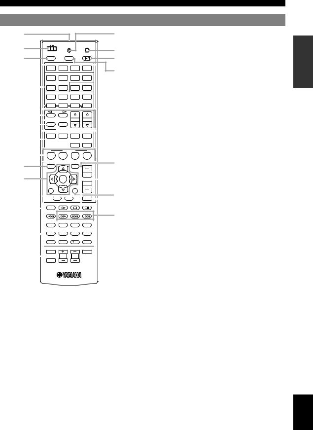
aRemote control signal transmitter
Transmits infrared signals.
bMAIN/ZONE2
Switches amplifiers (Main or Zone2) to be operated by the remote control (page 62).
cSOURCE POWER
Switches an external component on and off.
dInput selection keys
HDMI 1-4 Selects HDMI inputs 1 through 4. AV 1-6 Selects AV inputs 1 through 6.
AUDIO 1/2 |
Selects AUDIO inputs 1 and 2. |
V-AUX |
Selects a signal input from the VIDEO AUX jacks. |
PHONO |
Selects a signal input from the PHONO jacks. |
USB |
Selects a USB device connected to the USB port. |
DOCK |
Selects a Yamaha iPod universal dock/Bluetooth |
|
wireless audio receiver connected to the DOCK terminal. |
TUNER |
Selects the FM/AM tuner. |
SIRIUS |
Selects a SiriusConnect tuner as an input source. |
XM |
Selects an XM tuner as an input source. |
MULTI |
Selects a signal input from the MULTI CH |
|
INPUT jacks. |
qSLEEP
Switches the sleep timer operations (page 46).
rOPTION
Displays the Option menu (page 47).
sVOLUME +/–
Adjust the volume of this unit (page 22).
tDISPLAY
Displays the play information on the video monitor.
When an iPod is connected: Changes the operation mode of the iPod connected to the Yamaha iPod universal dock (page 42).
uMUTE
Turns the mute function on and off (page 23).
vHD Radio keys
TAG |
Stores “tag” data to the iPod or internal |
|
memory of this unit (page 31). |
PRG SELECT Selects an HD Radio audio program (page 31).
7 En
INTRODUCTION
English
Quick start guide
When you use this product for the first time, perform setup following the steps below. See the related pages for details on operations and settings.
Step 1: Prepare items for setup
Prepare speakers, DVD player, cables, and other items necessary for setup.
For example, prepare the following items for setting up a 7.1-channel sound system.
Front right speaker |
|
Video monitor |
Subwoofer |
|
|
Front left |
|
speaker |
Surround right speaker |
|
Center speaker
Surround Back Components right speaker
(such as DVD player)
Surround Back left speaker
Surround left speaker
Requirements |
qty. |
|
|
|
|
Speakers |
Front speaker |
2 |
|
|
|
|
Center speaker |
1 |
|
|
|
|
Surround speaker |
2 |
|
|
|
|
Surround back |
2 |
|
speaker |
|
|
|
|
Active subwoofer |
|
1 |
|
|
|
Speaker cable |
|
7 |
|
|
|
Subwoofer cable |
|
1 |
|
|
|
Reproduction component such as DVD player |
1 |
|
|
|
|
Video monitor such as TV |
1 |
|
|
|
|
Video cable or HDMI cable |
2 |
|
|
|
|
Audio cable |
|
2 |
|
|
|
y
•Prepare two magnetically shielded speakers (for front). The priority of the requirement of other speakers is as follows:
1 Two surround speakers
2 One center speaker
3 One (or two) surround back speaker(s)
•If your video monitor is a CRT, we recommend that you use magnetically shielded speakers.
•Video and audio cables are unnecessary if you use HDMI cables.
Step 2: Set up your speakers
Place your speakers in the room and connect them to this unit.
• |
Placing speakers |
P. 10 |
• |
Connecting speakers |
P. 11 |
y
•This unit has a YPAO (Yamaha Parametric Room Acoustic Optimizer) that automatically optimizes this unit based on room acoustic characteristics (audio characteristics of the speakers, speaker positions, and room acoustics, etc.).
You can enjoy good balanced sound without special knowledge by using the YPAO technology ( P. 19).
Step 3: Connect your components
Connect your TV, DVD player, or other components.
• Connecting a TV monitor or projector |
P. 14 |
• Connecting other components |
P. 15 |
• Connecting a multi-format player or an |
|
external decoder |
P. 16 |
• Connecting an external amplifier |
P. 16 |
• Connecting a USB storage device |
P. 17 |
• Connecting a Yamaha iPod universal dock or |
|
Bluetooth wireless audio receiver |
P. 17 |
• Connecting the FM and AM antennas |
P. 18 |
• Connecting an XM Mini-Tuner Home Dock |
P. 33 |
• Connecting a SiriusConnect tuner |
P. 37 |
|
|
Step 4: Turn on the power
Connect the power cable and turn on this unit.
• |
Connecting the power cable |
P. 18 |
• |
Turning this unit on and off |
P. 18 |
|
|
|
Step 5: Select the input source and start playback
Select the component connected in step 3 as an input source and start playback.
• |
Basic procedure |
P. 22 |
• |
Selecting sound field programs |
P. 25 |
y
•This unit supports the SCENE function (page 22) that changes the input source and sound field program at one time. Four scenes are preset for different purposes for Blu-ray disc, DVD and CD, and you can select from a scene from those just by pressing a remote control key.
8 En
PREPARATION
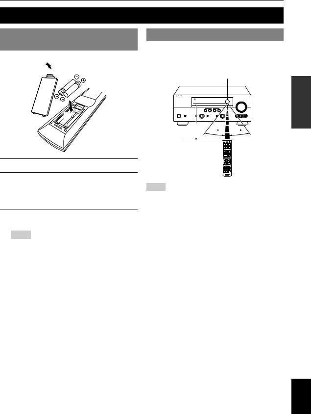
Preparing remote control
Installing batteries in the remote control
1  3
3
2
1Take off the battery compartment cover.
2Insert the two supplied batteries (AAA, R03, UM-4) according to the polarity markings (+ and –) on the inside of the battery compartment.
3Snap the battery compartment cover back into place.
Notes
•Change all batteries if you notice the following conditions:
–the operation range of the remote control narrows
–the transmit indicator does not flash or is dim
•Do not use old batteries together with new ones.
This may shorten the life of the new batteries or cause old batteries to leak.
•Do not use different types of batteries (such as alkaline and manganese batteries) together. Specification of batteries may be different even though they look the same.
•If you find leaking batteries, discard the batteries immediately, taking care not to touch the leaked material. If the leaked material comes into contact with your skin or gets into your eyes or mouth, rinse it away immediately and consult a doctor. Clean the battery compartment thoroughly before installing new batteries.
•Dispose of the old batteries correctly in accordance with your local regulations.
•If the remote control is without batteries for more than 2 minutes, or if exhausted batteries remain in the remote control, the contents of the memory may be cleared. In such a case, install new batteries and set the remote control code.
Using the remote control
The remote control transmits a directional infrared ray. Be sure to aim the remote control directly at the remote control sensor on this unit during operation.
Remote control sensor window
within 6 m (20 ft) |
30 |
30 |
|
Notes
•Do not spill water or other liquids on the remote control.
•Do not drop the remote control.
•Do not leave or store the remote control in the following conditions:
–places of high humidity, such as near a bath
–places of high temperatures, such as near a heater or stove
–places of extremely low temperatures
–dusty places
y
•You can operate external components with this remote control by setting the remote control code (page 63).
PREPARATION
English
9 En
Connections
Placing speakers
This unit supports up to 7.1-channel surround. We recommended the following speaker layout in order to obtain the
optimum surround effect.
7.1-channel speaker layout
|
C |
FL |
FR |
SW |
SW |
|
30˚ |
SL |
|
SR |
|
|
60˚ |
SL |
80˚ |
SR |
|
SBL |
SBR |
30 cm (12 in) or more
Speaker channels
■Front left and right speakers (FL and FR)
The front speakers are used for the front channel sounds (stereo sound) and effect sounds. Place these speakers at an equal distance from the ideal listening position. When using a screen, the appropriate top positions of the speakers are about 1/4 of the screen from the bottom.
■Center speaker (C)
The center speaker is for the center channel sounds (dialog, vocals, etc.). Place it halfway between the left and right speakers. When using a TV, place the speaker just above or just under the center of the TV with the front surfaces of the TV and the speaker aligned. When using a screen, place it just under the center of the screen.
6.1-channel speaker layout
|
|
C |
FL |
|
FR |
SW |
|
SW |
|
|
30˚ |
SL |
|
SR |
|
|
60˚ |
SL |
80˚ |
SR |
|
|
SB |
5.1-channel speaker layout
|
|
C |
FL |
|
FR |
SW |
|
SW |
|
|
30˚ |
SL |
|
SR |
|
|
60˚ |
SL |
80˚ |
SR |
■Surround left and right speakers (SL and SR)
The surround speakers are used for effect and surround sounds. Place them at the rear left and rear right facing the listening position. To obtain a natural sound flow in the 5.1-channel speaker layout, place them slightly further back than in the 7.1-channel speaker layout.
■Surround back left and right speakers (SBL and SBR) / Surround back speaker (SB)
The surround back left and right speakers are used for rear effect sounds. Place them at the rear of the room facing the listening position at least 30 cm (1 ft) away from each other, ideally at the same distance as that between the front left and right speakers.
In the 6.1-channel speaker layout, surround back left and right channel sound signals are mixed down and output from the single surround back speaker.
In the 5.1-channel speaker layout, surround back left and right channel sound signals are output from the surround left and right speakers.
■Subwoofer (SW)
The subwoofer speaker is used for bass sounds and lowfrequency effect (LFE) sounds included in Dolby Digital and DTS signals. Use a subwoofer with a built-in amplifier, such as the Yamaha Active Servo Processing Subwoofer System. Place it exterior to the front left and right speakers facing slightly inward to reduce reflections from a wall.
10 En

Connections
■ Presence left and right speakers (PL and PR) |
0.5 to 1 m (1 to 3 ft) |
0.5 to 1 m (1 to 3 ft) |
|
The presence speakers supplement the sound from the front speakers with extra ambient effects produced by the sound field programs (page 25). We recommend that you use the presence speakers especially for the CINEMA DSP sound field programs. To use the presence speakers, connect the speakers to EXTRA SP terminals and then set “Extra Speaker Assignment” to “Presence” (page 56).
PL |
FL
1.8 m (6 ft)
PR |

 FR
FR
1.8 m (6 ft)
C |
Connecting speakers
Connect your speakers to the respective terminals as follows, according to your speaker layout.
y
•Connect optional presence speakers or Zone2 speakers (page 61) to the EXTRA SP terminals.
•You can connect up to two subwoofers. When two subwoofers are connected, the same sound is output from them.
|
b |
a |
|
e |
d |
k |
j |
|
|
|
|
||||
HDMI 3 |
HDMI 4 |
ANTENNA |
|
GND |
AM |
|
|
|
|
HD Radio |
FM |
|
|
||
|
|
|
UNBAL. |
|
|
|
|
|
|
SPEAKERS |
EXTRA SP |
ZONE2/PRESENCE |
|||
|
|
SINGLE |
CLASS 2 WIRING |
||||
|
|
|
|
|
|||
E |
|
|
|
|
|
|
|
2V |
|
|
|
|
SURROUND BACK/ |
|
|
MAX. |
FRONT |
CENTER |
|
SURROUND |
|
|
|
|
BI-AMP |
|
|
||||
T |
|
|
|
|
|
|
|
|
|
|
|
|
|
|
|
|
CENTER |
|
|
|
SINGLE CENTER |
|
|
SUR.BACK |
SUBWOOFER |
FRONT |
SURROUND |
SUR. BACK |
1 |
SUBWOOFER |
2 |
INPUT |
AUDIO |
ZONE2 |
|
PRE OUT |
|
|
|
OUT |
OUT |
|
|
|
|
c |
g |
f |
h i |
|
|
■7.1-channel (with presence speakers)
Speakers |
Jacks on this unit |
a Front speaker L |
FRONT (L) |
b Front speaker R |
FRONT (R) |
c Center speaker |
CENTER |
d Surround speaker L |
SURROUND (L) |
e Surround speaker R |
SURROUND (R) |
f Surround back speaker L |
SURROUND |
|
BACK/BI-AMP (L) |
g Surround back speaker R |
SURROUND |
|
BACK/BI-AMP (R) |
■6.1-channel (with Zone2 speakers)
Speakers |
Jacks on this unit |
|
|
a Front speaker L |
FRONT (L) |
|
|
b Front speaker R |
FRONT (R) |
|
|
c Center speaker |
CENTER |
|
|
d Surround speaker L |
SURROUND (L) |
|
|
e Surround speaker R |
SURROUND (R) |
|
|
f Surround back speaker |
SURROUND |
|
BACK/BI-AMP (SINGLE) |
|
|
h Subwoofer 1 |
SUBWOOFER 1 |
|
|
i Subwoofer 2 (optional) |
SUBWOOFER 2 |
|
|
j Zone2 speaker L (optional) |
EXTRA SP (L) |
|
|
k Zone2 speaker R (optional) |
EXTRA SP (R) |
|
|
■5.1-channel (with Zone2 speakers)
Speakers |
Jacks on this unit |
|
|
a Front speaker L |
FRONT (L) |
|
|
b Front speaker R |
FRONT (R) |
|
|
c Center speaker |
CENTER |
|
|
d Surround speaker L |
SURROUND (L) |
|
|
e Surround speaker R |
SURROUND (R) |
|
|
h Subwoofer 1 |
SUBWOOFER 1 |
|
|
i Subwoofer 2 (optional) |
SUBWOOFER 2 |
|
|
j Zone2 speaker L (optional) |
EXTRA SP (L) |
|
|
k Zone2 speaker R (optional) |
EXTRA SP (R) |
|
|
h Subwoofer 1 |
SUBWOOFER 1 |
i Subwoofer 2 (optional) |
SUBWOOFER 2 |
j Presence speaker L (optional) |
EXTRA SP (L) |
k Presence speaker R (optional) |
EXTRA SP (R) |
PREPARATION
English
11 En
Connections
Caution
•A speaker cable is a pair of insulated cables running side by side in general. One of the cables is colored differently or striped to indicate a polarity. Connect one end of the colored/striped cable to the “+” (red) terminal of this unit and the other end to that of your speaker, and connect one end of the other cable to the “–” (black) terminal of this unit and the other end to that of your speaker.
•Before connecting the speakers, be sure to disconnect the power cable.
•Do not let the bare speaker wires touch each other or any metal part of this unit. This could damage this unit and/or speakers. If the circuit shorts out, “CHECK SP WIRES!” appears on the front panel display when this unit is turned on.
•If images on the monitor (CRT) are distorted, place the speakers away from the video monitor. If it does not work, use magnetically shielded speakers.
•Use speakers with an impedance of 6-ohm or larger. Set speaker impedance in the advanced setup menu before
connecting the speakers (page 64). You can also use 4-ohm speakers as the front speakers when you set “SP IMP.” to “6ΩMIN”.
■Connecting speaker cables
1Remove approximately 10 mm (0.4 in) of insulation from the end of each speaker cable and then twist bare wires of the cable together so that they will not cause a short circuits.
10 mm (0.4 in)
2Loosen the knob, insert the twisted bare wires into the hole and then tighten the knob.
2 
1
Red: positive (+)
Black: negative (–)
3
Connecting the banana plug (Except Korea, U.K., Europe, Russia and Asia models)
Tighten the knob and then insert the banana plug into the end of the terminal.
■Using bi-amplification connections
You can make bi-amplification connections to one speaker system which supports bi-amplification connection as shown below. To activate the connections, set “BI-AMP” to “ON” in the advanced setup menu (page 64).
Front speakers
Right Left
This unit
FRONT |
SURROUND BACK/ |
|
BI-AMP |
Caution
Before making bi-amplification connections, remove any brackets or cables that connect a woofer with a tweeter. Refer to the instruction manuals of speakers for details.
When not making bi-amplification connections, make sure that the brackets or cables are connected before connecting the speaker cables.
Note
•You cannot use surround back speakers or extra speakers (presence and Zone2 speakers) when bi-amplification connections are made.
Banana plug
12 En
Connections
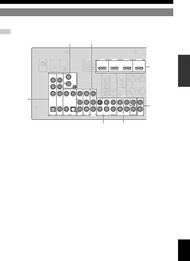
Information on jacks and cable plugs
This unit has the following input and output jacks. Use jacks and cables appropriate for components that you are connecting.
■Audio jacks
Jack and cables |
Description |
|
Analog audio jacks |
To transmit conventional analog |
|
(white) |
stereo audio signals. Use stereo pin |
|
cables. Connect red plugs to red |
||
|
||
L |
jacks (R) and white plugs to white |
|
|
jacks (L). |
|
R |
|
|
(red) |
|
|
COAXIAL jacks |
To transmit coaxial digital audio |
|
(orange) |
signals. Use pin cables for digital |
|
audio signals. |
||
|
||
C |
|
|
COAXIAL |
|
|
OPTICAL jacks |
To transmit optical digital audio |
|
|
signals. Use optical fiber cables for |
|
O |
optical digital audio signals. |
|
OPTICAL |
|
■Video jacks
Jack and cables |
Description |
VIDEO jacks |
To transmit conventional |
VIDEO |
composite video signals. Use video |
|
|
V |
pin cables. |
|
|
(yellow) |
|
■Video/audio jacks
Jack and cables |
Description |
HDMI jacks |
To transmit digital video and |
|
digital audio signals. Use HDMI |
HDMI |
cables. |
HDMI |
|
y
•We recommend that you use a commercially available 19-pin HDMI cable no longer than 5 meters (16 feet) with the HDMI logo printed on it.
•Use a conversion cable (HDMI jack ↔ DVI-D jack) to connect this unit to other DVI components.
•You can check the potential problem about the HDMI connection (page 48).
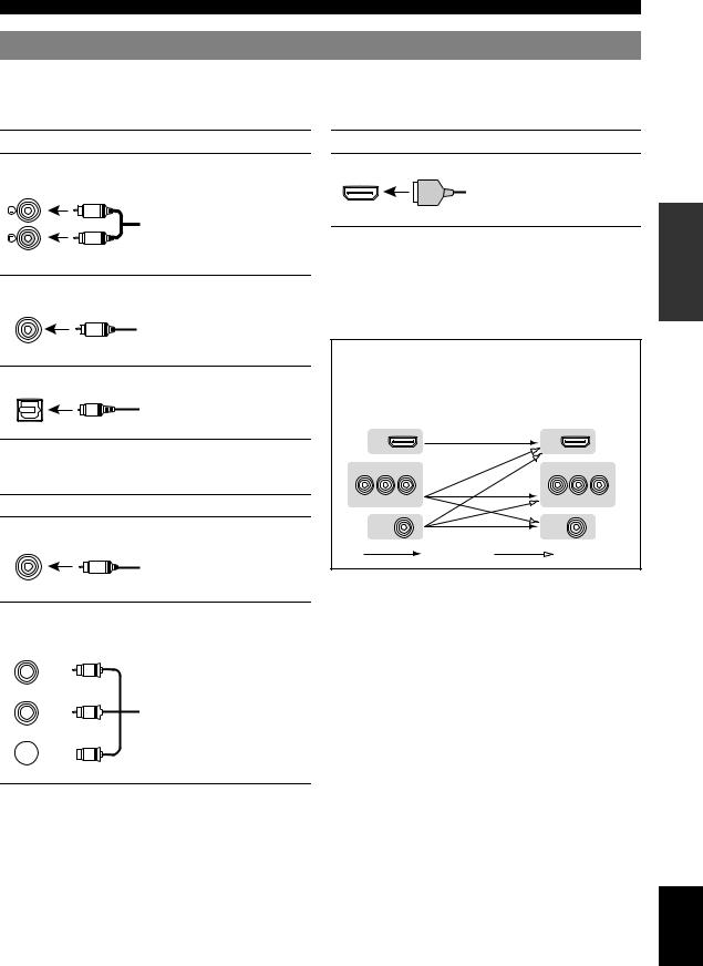
This unit automatically converts input video signals and outputs the signals to the HDMI OUT jack and MONITOR OUT (COMPONENT VIDEO and VIDEO) jacks (video conversion).
Input |
Output |
|
|
HDMI |
|
HDMI |
|
COMPONENT VIDEO |
|
COMPONENT VIDEO |
|
PR PB |
Y |
PR PB |
Y |
VIDEO |
|
VIDEO |
|
|
Through |
Converted |
|
COMPONENT VIDEO jacks
COMPONENT
VIDEO
PR 

 PR
PR
(red)
PB 

 PB
PB
(blue)
Y 


 Y
Y
(green)
To transmit component video signals that include luminance (Y), chrominance blue (PB) and chrominance red (PR) components. Use component video cables.
PREPARATION
English
13 En
Connections
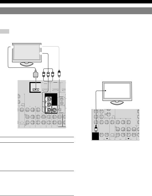
Connecting a TV monitor or projector
According to the types of video input jacks available on your video monitor (such as a TV or projector), choose one of the connection methods as shown below. When you connect video players such as a DVD player to this unit with an HDMI connection, connect your video monitor to this unit with an HDMI connection.
Note
• Make sure that this unit and other components are unplugged from the AC wall outlets.
TV, or projector |
Outputting TV sounds from this unit |
|
|
ac b
HDMI |
Y PB PR |
V |
To output sound of a TV from this unit, make connection between one of the AV 1-6 jacks of this unit and an audio output jack of the TV.
If the TV supports an optical digital output, we recommend that you use the AV 1 jack. Connecting to the AV 1 jack allows you to switch an input source to the AV 1 jack with a just a single key operation using the SCENE function (page 22).
|
|
|
TV |
HDMI OUT |
HDMI 1 |
HDMI 2 |
HDM |
|
(BD/DVD) |
|
|
|
|
|
Digital output |
|
|
|
(optical) |
PHONO |
MONITOR OUT |
|
|
|
COMPONENT |
|
|
|
VIDEO |
|
REMOTE |
|
|
|
|
|
PR |
|
IN |
GND |
|
|
OUT |
|
PB |
VIDEO |
|
Y |
|
|
12V |
PR |
PR |
0.1A MAX. |
|
|
TRIGGER OUT
GND
PB |
PB |
VIDEO
|
|
|
|
|
|
|
|
Y |
Y |
L |
OPTICAL |
|
|
|
|
FRONT |
SURROUND |
SUR.B |
|
|
|
|
|
AV |
|
|
|||
|
AV 4 |
AV 5 |
AV 6 |
AUDIO1 |
AUDIO2 |
MULTI CH INP |
|
||
|
OUT |
|
|||||||
|
|
|
|
|
|
|
|
|
O |
■To connect an HDMI video monitor
Jacks on components |
Jacks on this unit |
OPTICAL COAXIAL COAXIAL OPTICAL
( TV ) |
(CD) |
|
AV |
AV 1 |
AV 2 |
AV 3 |
AV 4 |
AV 5 |
AV 6 |
OUT |
AUDIO1 |
AUD |
a HDMI input |
HDMI OUT |
|
|
y
•This unit supports the HDMI control function (page 46). If your TV supports the HDMI control function, you can control this unit with the remote control of your TV.
■To connect component video monitor
Jacks on components |
Jacks on this unit |
|
|
b Component video output |
MONITOR OUT |
|
(COMPONENT VIDEO) |
|
|
■To connect composite video monitor
Jacks on components |
Jacks on this unit |
|
|
c Video input (composite) |
MONITOR OUT (VIDEO) |
|
|
14 En
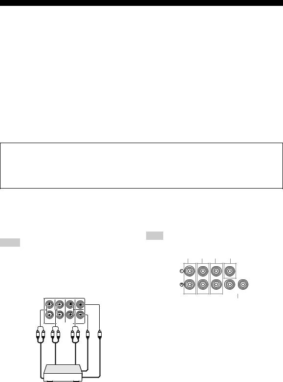
Connections
Connecting other components
This unit has input and output terminals for respective input and output sources. You can reproduce sound and movies from input sources selected with the front panel display or remote control.
Note
• Make sure that this unit and other components are unplugged from the AC wall outlets.
Audio input (PHONO) |
Audio / video output (AV OUT) |
Audio / video input (AV 1-6)
SIRIUS |
DOCK |
XM |
HDMI OUT |
HDMI 1 |
HDMI 2 |
(BD/DVD)
PHONO |
|
MONITOR OUT |
COMPONENT |
COMPONENT |
|
VIDEO |
|
VIDEO |
PR |
PR |
|
GND |
|
|
PB |
PB |
VIDEO |
VIDEO |
|
|
Y |
Y |
|
|
COAXIAL |
COAXIAL |
|
|
|
|
|
|
|
|
|
OPTICAL |
OPTICAL |
|
|
|
|
|
FRONT |
||||
( TV ) |
|
(CD) |
|
|
|
|
|
AV |
|
|
|
AV 2 |
AV 4 |
AV 5 |
AV 6 |
AUDIO1 |
AUDIO2 |
|
|||||
AV 1 |
AV 3 |
OUT |
|
||||||||
HDMI 3 HDMI 4
|
|
HDMI input |
|
|
(HDMI 1-4) |
REMOTE |
|
|
IN |
|
|
OUT |
|
|
12V |
|
|
0.1A MAX. |
FRONT |
|
TRIGGER OUT |
|
|
|
CENTER |
|
|
|
Audio output |
|
|
(AUDIO OUT) |
SURROUND SUR.BACK |
SUBWOOFER |
ZO |
MULTI CH INPUT |
AUDIO |
|
OUT |
O |
Audio input (AUDIO 1/2) Multi channel audio input (MULTI CH INPUT)
■Audio and video player / Set-top box
Output jacks on the connected external component |
Input sources/jacks of this unit |
||||
|
|
|
|
|
|
External |
Signal |
Output jack |
Input source |
Input jack |
|
component |
|||||
|
|
|
|
||
|
|
|
|
|
|
External component |
Audio/Video |
HDMI output |
HDMI 1 (BD/DVD) |
HDMI 1 |
|
with HDMI output |
|
|
|
|
|
|
|
HDMI 2 |
HDMI 2 |
||
|
|
|
|||
|
|
|
|
|
|
|
|
|
HDMI 3 |
HDMI 3 |
|
|
|
|
|
|
|
|
|
|
HDMI 4 |
HDMI 4 |
|
|
|
|
|
|
|
External component |
Audio |
Optical digital output |
AV 1 (TV) |
OPTICAL |
|
with component video |
Video |
Component video |
|
COMPONENT VIDEO |
|
output |
|
||||
|
|
|
|
||
Audio |
Coaxial digital output |
AV 2 |
COAXIAL |
||
|
|||||
|
Video |
Component video output |
|
COMPONENT VIDEO |
|
|
|
|
|
|
|
External component |
Audio |
Coaxial digital output |
AV 3 (CD) |
COAXIAL |
|
with composite video |
Video |
Composite output |
|
VIDEO |
|
output |
|
||||
|
|
|
|
||
Audio |
Optical digital output |
AV 4 |
OPTICAL |
||
|
|||||
|
Video |
Composite output |
|
VIDEO |
|
|
|
|
|
|
|
|
Audio |
Analog audio output |
AV 5 |
Analog audio |
|
|
Video |
Composite output |
|
VIDEO |
|
|
|
|
|
|
|
|
Audio |
Analog audio output |
AV 6 |
Analog audio |
|
|
Video |
Composite output |
|
VIDEO |
|
|
|
|
|
|
|
y
•Input sources in parentheses are recommended to connect to the respective jacks. If your Yamaha component has the remote in/out terminal, you can switch the input source to that component with a single key operation using the SCENE function (page 22).
•You can change the name of the input source displayed on the front panel display as necessary (page 60).
•See page 61 on how to use the ZONE2 OUT jacks.
PREPARATION
English
15 En
Connections
■ Audio player
Output jacks on the connected external component |
Input sources/jacks of this unit |
||
|
|
|
|
External component |
Output jack |
Input source |
Input jack |
|
|
|
|
External component with optical digital |
Optical digital output |
AV 1 (TV) |
OPTICAL |
output |
|
|
|
|
AV 4 |
OPTICAL |
|
|
|
||
|
|
|
|
External component with coaxial digital |
Coaxial digital output |
AV 2 |
COAXIAL |
output |
|
|
|
|
AV 3 (CD) |
COAXIAL |
|
|
|
||
|
|
|
|
External component with analog audio |
Analog audio output |
AV 5 |
Analog audio |
output |
|
|
|
|
AV 6 |
Analog audio |
|
|
|
||
|
|
|
|
|
|
AUDIO 1 |
Analog audio |
|
|
|
|
|
|
AUDIO 2 |
Analog audio |
|
|
|
|
Turntable |
Analog audio output |
PHONO |
Analog audio |
|
|
|
|
y
•We recommend connecting the coaxial digital output terminal of a CD player to the AV3 jack.
•When connecting a turntable with a low-output MC cartridge to the PHONO jacks, use an in-line boosting transformer or MC-head amplifier.
•Connect your turntable to the GND terminal of this unit to reduce noise in the signal.
About audio/video output terminals
Among the analog audio and analog video signals input to this unit via input terminals, the audio/video signals of the selected input sources are output from the AV OUT jacks and AUDIO OUT jacks. An HDMI input signal, COMPONENT VIDEO input signal or digital audio input signal cannot be output.
When using the AV OUT jacks: connect an external component to the VIDEO or analog audio terminal. When using the AUDIO OUT jacks: connect an external component to the analog audio terminal.
■Connecting a multi-format player or an
external decoder
This unit is equipped with 8 additional input jacks (Front L/R, Center, Surround L/R, Surround Back L/R and Subwoofer) for analog multi-channel input from a multiformat player, external decoder, etc.
Notes
•When you select “MULTI CH” as the input source, the digital sound field processor is automatically disabled.
•Since this unit does not redirect signals input at the MULTI CH INPUT jacks to accommodate for missing speakers, connect at least a 5.1- channel speaker system when using this feature.
•You can specify a video signal to be output during a multi-channel audio reproduction (page 49). If your DVD player has analog multi-channel output jacks, connect them to the MULTI CH INPUT jacks while making a video connection (component video or composite).
■Connecting an external amplifier
If you want to use another amplifier, connect an external amplifier to the PRE OUT jacks. Each PRE OUT jack outputs the same channel signals as the corresponding speaker terminals.
Note
•When you make connections to the PRE OUT jacks, do not make any connections to the speaker terminals.
a b c d
SINGLE CENTER
|
|
|
|
|
|
|
|
|
|
|
|
|
|
|
|
|
|
|
|
|
|
|
|
|
|
|
|
|
|
|
|
|
|
|
|
|
|
|
|
|
|
|
|
|
|
|
|
|
|
|
|
|
|
|
|
|
|
|
|
|
|
|
|
|
|
|
|
|
|
|
|
FRONT SURROUND SUR. BACK |
|
1 SUBWOOFER 2 |
|||||
PRE OUT
CENTER
|
|
FRONT |
SURROUND |
SUR.BACK |
SUBWOOFER |
|
|
|
|
MULTI CH INPUT |
|
|
|
L |
R |
L |
R |
R |
L |
|
out Front |
|
Surround out |
|
Surround out back |
Subwoofer |
out Center |
|
|
|
|
|
out |
|
Multi-format player or external decoder (7.1-channel output)
e
aFRONT PRE OUT jacks
Front channel output jacks.
bSURROUND PRE OUT jacks
Surround channel output jacks.
cSUR.BACK PRE OUT jacks
Surround back output jacks. When you only connect one external amplifier for the surround back channel, connect it to the left SUR.BACK (SINGLE) jack.
y
•To output surround back channel signals at these jacks, set “Surround Speaker” to any parameter except “None” (page 56).
dCENTER PRE OUT jack
Center channel output jack.
eSUBWOOFER PRE OUT 1/2 jack
Connect a subwoofer with a built-in amplifier.
16 En
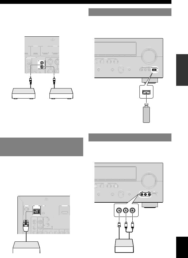
■ Transmitting/receiving remote control signals
When the components have the capability of the transmission of the remote control signals, connect the REMOTE IN and REMOTE OUT jacks to the remote control input and output jack with the monaural analog mini cable as follows.
Connections
Connecting a USB storage device
Connect a USB memory device or USB portable audio player to the USB port on the front panel of this unit. For information about USB storage devices supported by this unit, see page 45.
DMI 1 |
HDMI 2 |
HDMI 3 |
HDMI 4 |
BD/DVD) |
|
|
VOLUME |
FM |
AM |
EMORY |
l |
PRESET |
h |
l CATEGORY |
h |
l TUNING/CH |
h |
MONITOR OUT |
|
|
|
|
COMPONENT |
|
|
SCENE |
|
VIDEO |
REMOTE |
|
|
|
|
|
|
|
|
|
BD/DVD |
TV |
CD |
RADIO |
PR |
IN |
|
|
|
|
|
|
INPUT |
|
|
|
OUT |
PURE DIRECT |
OPTIMIZER MIC |
VIDEO AUX |
USB |
PB |
STRAIGHT |
|
|
||
VIDEO |
|
|
|
|
|
|
EFFECT |
|
VIDEO |
AUDIO |
|
Y
Remote |
Remote |
control out |
control in |
USB
PREPARATION
Infrared signal |
IR flasher or Yamaha |
receiver or Yamaha |
component |
component |
(CD or DVD player, etc.) |
y
•If connecting a Yamaha component that supports the SCENE control signal reception to the REMOTE OUT jack of this unit, you can start playback on the Yamaha component by using the SCENE function (page 22).
•If connecting a component other than Yamaha products to the REMOTE OUT jack of this unit, set “SCENE IR” to “OFF” in the advanced setup menu (page 64).
Connecting a Yamaha iPod universal dock or Bluetooth™ wireless audio receiver
This unit has the DOCK terminal, to which you can connect a Yamaha iPod universal dock (YDS-11, sold separately) or a Bluetooth wireless audio receiver (YBA10, sold separately). You can play an iPod or a Bluetooth component with this unit by connecting it to the DOCK terminal.
Use a dedicated cable for connection between the dock/ receiver and this unit.
USB memory device or
USB portable audio player
Using the VIDEO AUX jacks
Use the VIDEO AUX jacks on the front panel to connect a game console or a video camera to this unit. Be sure to turn down the volume of this unit and other components before making connections.
VOLUME
FM |
AM |
EMORY |
l |
PRESET |
h |
l CATEGORY |
h |
l TUNING/CH |
h |
SCENE
BD/DVD |
TV |
CD |
RADIO |
INPUT
VIDEO AUX |
USB |
STRAIGHT |
PURE DIRECT |
OPTIMIZER MIC |
EFFECT
VIDEO AUDIO
SIRIUS |
DOCK |
XM |
|
HDMI OUT |
PHONO
COMPONENT
VIDEO
PR
GND
PB
VIDEO
Y
Yamaha iPod universal dock or
Bluetooth wireless audio receiver
VIDEO |
L AUDIO R |
outputVideo |
V |
L |
R |
output |
audioAnalog |
English
Game console or video camera
17 En
Connections
Connecting the FM and AM antennas
An indoor FM antenna and an AM loop antenna are supplied with this unit. Connect these antennas properly to the respective jacks.
Indoor FM antenna |
Outdoor AM antenna |
AM loop |
||
|
|
Connect a 5 to 10 m (16 to |
antenna |
|
|
|
33 ft) vinyl-covered wire, |
|
|
|
|
and extend it outdoors |
|
|
|
|
(use the AM loop antenna |
|
|
|
|
together with this |
|
|
|
|
antenna). |
|
|
HDMI 3 |
HDMI 4 |
ANTENNA |
GND AM |
|
|
|
HD Radio FM |
|
|
|
|
UNBAL. |
|
|
|
|
SPEAKERS |
EXTRA SP |
ZONE2/PRESENCE |
|
|
SINGLE |
CLASS 2 WIRING |
|
|
|
|
||
REMOTE |
|
|
|
|
IN |
|
|
|
|
|
Ground (GND terminal) |
|
||
|
The GND terminal is not for earth grounding. |
|||
|
To reduce noises, connect a ground bar or a |
|||
|
vinyl-covered wire with a copper plate at its tip, |
|||
|
and place it in the moist ground. |
|
||
Connecting the power cable
After all connections are complete, plug the power cable of this unit into an AC wall outlet.
To the AC wall outlet
NE2/PRESENCE
CLASS 2 WIRING
 Power cable
y
•The supplied antennas are normally sensitive enough to obtain good reception.
•Position the AM loop antenna away from this unit.
•If you cannot get good reception, we recommend that you use an outdoor antenna. For details, consult the nearest authorized Yamaha dealer or service center.
•Always use the AM loop antenna even when the outdoor antenna is connected.
Assembling the AM loop antenna
Connecting the AM loop antenna
The wires of the AM loop antenna have no polarity. You can connect either wire to the AM terminal and the other to the GND terminal.
Turning this unit on and off
1Press KMAIN ZONE ON/OFF on the front panel (or pPOWER on the remote control) to turn on this unit.
2Press KMAIN ZONE ON/OFF (or pPOWER) again to turn off this unit
(standby mode).
y
•The unit needs a few seconds until ready to play back.
•You can also turn on this unit by pressing PSCENE (or hSCENE).
•This unit consumes a small amount of electricity even in the standby mode. We recommend disconnecting the power cable from the AC wall outlet.
Caution
Do not unplug this unit while it is turned on. Doing so may damage this unit or cause the settings of this unit to be saved incorrectly.
Press and hold |
|
Insert |
Release |
||||||||||||||||
|
|
|
|
|
|
|
|
|
|
|
|
|
|
|
|
|
|
|
|
18 En
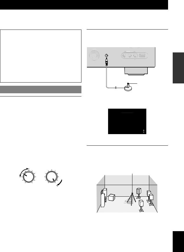
Optimizing the speaker setting for your listening room (YPAO)
This unit has a Yamaha Parametric Acoustic Optimizer (YPAO). With the YPAO, this unit automatically adjusts the output characteristics of your speakers based on speaker position, speaker performance, and the acoustic characteristics of the room. We recommend that you first adjust the output characteristics with the YPAO when you use this unit.
Caution
•Be advised that it is normal for loud test tones to be output during the “Auto Setup” procedure. Do not allow small children to enter the room during the procedure.
•To achieve the best results, make sure the room is as quiet as possible while the “Auto Setup” procedure is in progress. If there is too much ambient noise, the results may not be satisfactory.
y
•You can manually adjust the output characteristics of your speakers with “Manual Setup” in the Setup menu (page 55).
Using Auto Setup
1Check the following points.
Before starting the automatic setup, check the following.
•All speakers and subwoofer are connected properly.
•Headphones are disconnected from this unit.
•The video monitor is connected properly.
•This unit and the video monitor are turned on.
•This unit is selected as the video input source of the video monitor.
•The connected subwoofer is turned on and the volume level is set to about half way (or slightly less).
•The crossover frequency controls of the connected subwoofer are set to the maximum.
|
CROSSOVER/ |
VOLUME |
HIGH CUT |
2Connect the supplied optimizer microphone to the SOPTIMIZER MIC jack on the front panel.
INPUT
OPTIMIZER MIC |
VIDEO AUX |
USB |
|
|
|
VIDEO |
AUDIO |
|
Optimizer microphone
“MIC ON. View GUI MENU” appears on the front panel display.
The GUI screen appears on the video monitor.
Auto Setup
Extra Speaker Assignment
Zone2 Presence None
EQ Type
Flat Front Natural
Start
Move focus 
Start 
y
• You can bring up the above menu screen from the Setup menu (page 55).
3Place the optimizer microphone at your normal listening position on a flat level surface with the omni-directional microphone heading upward.
Optimizer microphone
MIN |
MAX |
MIN |
MAX |
Subwoofer
y
•It is recommended that you use a tripod or something similar to fix the optimizer microphone at the same height as your ears would be when seated in your listening position. You can fix the optimizer microphone to the tripod with the attaching screw of the tripod.
PREPARATION
English
19 En
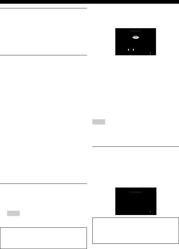
Optimizing the speaker setting for your listening room (YPAO)
4When the speakers are connected to EXTRA SP terminals, press jCursor krepeatedly to select “Extra Speaker Assignment” and then press jCursor l/ hto select how to use EXTRA SP terminals from “Zone2”, “Presence” or “None”.
If this unit does not work when you press jCursor, press iON SCREEN once and then operate this unit.
5To select sound characteristics for adjustment, press jCursor nto select “EQ Type” and then press jCursor l/ h.
If this unit does not work when you press jCursor, press iON SCREEN once and then operate this unit.
This unit has a parametric equalizer that adjusts the output levels for each frequency range. The equalizer is adjusted to produce a cohesive sound field based on automatically measured speaker characteristics.
In “EQ Type”, you can select the following parametric equalizer characteristics suitable for the desired sound characteristics.
Natural
This adjusts all speakers to achieve natural sound. Select this if sounds in the high frequency range seem too strong when “EQ Type” is set to “Flat”.
Flat
This adjusts each speaker to obtain the same characteristics. Select this if your speakers have similar qualities.
Front
This adjusts each speaker to obtain the same characteristics as the front left and right speakers. Select this if your front left and right speakers have significantly better qualities than the other speakers.
6Press jCursor nto select “Start” and then press jENTER to start the setup procedure.
A countdown starts and a measurement starts in 10 seconds. A loud test tone is output during measurement.
Notes
•During the automatic setup procedure, do not perform any operation on this unit.
•Press jCursor kto cancel the automatic setup procedure.
Measurement takes about 3 minutes. To obtain precise results, stay where you will not disturb the measurement, such as to the side of or behind the speakers or outside the room.
When measurement is successfully completed, “YPAO Complete” appears on the front panel display and the measurement result appears on the GUI screen.
Auto Setup
Result
Speaker Config : 3 /4 / 0.1
Distance (Min / Max) : 8.0ft / 8.5ft
Level (Min / Max) : -3.5dB / +4.5dB
Set |
Cancel |
Finish
Select items
Speaker Config
Displays the number of speakers connected to this unit in the following order:
Total of Front and Center/Total of Surround and Surround Back/Subwoofer
Distance (Min / Max)
Displays the speaker distance from the listening position in the following order:
Closest speaker distance/Farthest speaker distance
Level (Min / Max)
Displays the speaker output levels in the following order: Lowest speaker output level/Highest speaker output level
Notes
•If “Error” appears on the GUI screen during “Auto Setup”, measurement is canceled and the type of error is displayed. For details, see “When an error message is displayed during measurement” (page 21).
•If problems occur during measurement, “Check xx warning(s)” (xx indicates the number of warnings) appears in red. For details, see “When a warning message is displayed after measurement” (page 21).
7Press jENTER to confirm the settings.
The speaker characteristics are adjusted according to measurement results.
To cancel the operation, press jCursor l/ hto select “Cancel” and press jENTER.
When the following screen appears, remove the optimizer microphone. “Auto Setup” is now complete.
Auto Setup
Auto Setup Completed !
Please disconnect the micorphone (Then this screen will automatically disappear)
Return
The optimizer microphone is sensitive to heat. Store it in a cool place and away from direct sunlight after measurement. Do not leave it in a place where it will be subjected to high temperatures such on an AV component.
y
•If you do not want to apply the measurement results, select “Cancel”.
•Perform “Auto Setup” again if you change the number or positions of speakers.
•If you press jENTER before removing the optimizer microphone, “Auto Setup” of “Speaker Setup” in the Setup menu (page 55) is displayed.
20 En

Optimizing the speaker setting for your listening room (YPAO)
When an error message is displayed during measurement
If an error is detected during measurement, the measurement is canceled and “Error” appears on the GUI screen. Check the error and solve the problem. For details on each error message, see page 75.
Press jCursor nonce, press jCursor l/ h to select “Retry” or “Exit” and then press jENTER.
Error
E-1 : No Front Speakers
FrontL/R channel signals are not detected.
Check wiring and connections of the front L/R speakers.
Retry Exit
Move focus
Retry
Performs “Auto Setup” again.
Exit
Terminates the measurement and “Auto Setup”.
y
•When “E-5:NOISY” appears, you can continue measurement. To continue measurement, select “Proceed”. However, we recommend that you solve the problem first and then perform measurement again.
When a warning message is displayed after measurement
If a problem occurs during measurement, “Check xx warning(s)” appears on the GUI screen. Check the warning and solve the problem. For details on each warning message, see page 76.
Auto Setup
Result
Speaker Config : 3 /4 / 0.1
Distance (Min / Max) : 8.0ft / 8.5ft
Level (Min / Max) : -3.5dB / +4.5dB
 Check 2 warnings
Set Cancel
See details
Select items
y
•Optimization will not be performed while a warning message is displayed. We recommend that you solve the problem and perform “Auto Setup” again.
1Press jCursor n/ kto select “Check xx warning(s)” and then press jENTER.
Details of the warning message are displayed. If there are multiple warning messages, you can display the next message using jCursor h.
2To return to the top result display, press jENTER again.
PREPARATION
English
21 En
BASIC OPERATION
Playback
Basic procedure
1Turn on external components (TV, DVD player, etc.) connected to this unit.
2Rotate the RINPUT selector (or press dInput selection key) to select an input source.
The name of the selected input source is displayed for a few seconds.
Input source name
VOL.
AV1
y
•You can also select an input source from the GUI screen (page 23).
•You can change the input source name displayed on the front panel display or GUI screen as necessary (page 60).
3Play the external component that you have selected as the source input, or select a radio station on the tuner.
Refer to the operating instructions of the external component for details on playback. For selecting radio stations or playback of an iPod, Bluetooth component or USB storage device using this unit, see the following.
•FM/AM radio tuning (page 29)
•iPod playback (page 42)
•Bluetooth component playback (page 44)
•USB storage device playback (page 45)
4Turn the JVOLUME control (or press sVOLUME +/–) to adjust the volume.
Volume
VOL.
SW
Volume -18.5dB L C R
SL SR
Note
When you play back a DTS-CD, noise may be output in some conditions, which may cause a speaker malfunction. Make sure that the volume is set to low before starting playback. If noise is output, do the following.
1) When only noise is output
If a DTS bitstream signal is not properly input to this unit, only noise is output. Connect the playback component to this unit by digital connection and play back the DTS-CD. If the condition is not improved, the problem may results from the playback component. Consult the manufacturer of the playback component.
2) When noise is output during playback or skip operation Before playing back the DTS-CD, display the Option menu after selecting the input source and set “Decoder Mode” to “DTS” (page 48).
Using the SCENE function
This unit has a SCENE function that allows you to change input sources and sound field programs with one key. Four scenes are available for different usages, such as playing movies or music. The following input sources and sound field programs are provided as the initial factory settings.
Keys |
Input source |
Sound field program |
|
|
|
BD/DVD |
HDMI 1 |
Straight |
|
|
|
TV |
AV 1 |
Straight |
|
|
|
CD |
AV 3 |
Straight |
|
|
|
RADIO |
TUNER |
7ch Enhancer |
|
|
|
y
•When this unit is on standby, you can turn on this unit by pressing
PSCENE (or hSCENE).
•If you connect a Yamaha DVD/CD player that has the capability of the SCENE control signals to the REMOTE OUT jack of this unit, you can start playback on the player by using the SCENE function.
Selecting a SCENE
Press PSCENE (or hSCENE).
y
• You can also select a SCENE from the GUI screen (page 23).
22 En
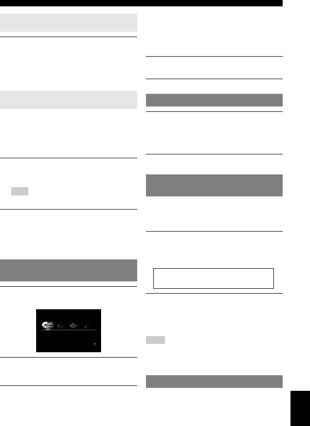
Registering input source/sound field program
Select the desired input source/sound field program and then press and hold PSCENE (or hSCENE) key to edit until “SET Complete” appears on the front panel display.
y
•If you change the input source setting, register the remote control code of an external component to the input source (page 63).
Switching remotely controlled external components linked to scene selections
You can operate an external component with the remote control of this unit by setting a remote control code for the external component for each input source. Setting remote control codes for desired input sources allows you to switch between external components linked to scene selections.
1Register the remote control code of an external component to the desired input source (page 63).
Note
•This feature is not available for TUNER, SIRIUS and XM input sources.
2While holding down the desired hSCENE key, press and hold the dInput selection key to which you registered a remote control code in step 1.
From now on the external component can be remotely controllable just by selecting a scene.
Selecting an input source on the GUI screen
1Press iON SCREEN on the remote control.
The GUI screen appears on the video monitor.
Select Scene
BD/DVD TV CD RADIO
2Use jCursor k/ nrepeatedly to switch the page and jCursor l/ hrepeatedly to select the desired input source.
Category |
Input source |
|
|
Select Scene |
BD/DVD, TV, CD, RADIO |
|
|
|
Playback |
|
|
Category |
Input source |
|
|
Select Media |
USB, DOCK, SIRIUS, XM, |
|
TUNER, PHONO, V-AUX, |
|
MULTI CH |
|
|
Select Input |
HDMI1-4, AV1-6, AUDIO1/2 |
y
•If an input source you want to select is available in “Select Scene”, you can select the desired input source and sound field program at once.
3 Press jENTER.
Muting audio output
1Press uMUTE on the remote control to mute the audio output.
The MUTE indicator on the front panel display flashes while audio output is muted.
2Press uMUTE again to resume audio output.
Adjusting high/low frequency sounds (tone control)
You can adjust the balance of the high frequency range (Treble) and low frequency range (Bass) of sounds output from the front left and right speakers to obtain desired tone.
1Press MTONE CONTROL on the front panel repeatedly to select “Treble” or “Bass”.
The current setting is displayed on the front panel display.
Treble 0.0dB
2Rotate the NPROGRAM selector to adjust the frequency range.
Control range: –10.0 dB to +10.0 dB The display returns to the previous screen automatically in few seconds.
Notes
•The tone control settings are not effective when this unit is in the Pure Direct mode or “MULTI CH” is selected as an input source.
•If you set the balance extremely off, sounds may not match those from other channels well.
Enjoying pure hi-fi sound
Use Pure Direct mode to enjoy the pure high fidelity sound of the selected source. When Pure Direct mode is activated, this unit plays back the selected source with the least circuitry.
OPERATION |
BASIC |
|
|
English
23 En
Playback
Press QPURE DIRECT (or gPURE DIRECT) to turn the Pure Direct mode on or off.
QPURE DIRECT lights up when you set Pure Direct mode on.
The following features are disabled in the Pure Direct mode.
–sound field program, tone control
–display and operation of the Option menu and Setup menu
–multi-zone function
y
•The font panel display automatically turns off while this unit in the Pure Direct mode.
Using your headphones
Plug your headphones in the LPHONES jack on the front panel.
When you select a sound field program while using the headphones, the mode is automatically set to SILENT CINEMA mode.
Notes
•When you connect headphones, no signals are output at the speaker terminals.
•When multi-channel signals are processed, sounds in all channels are divided to left and right channels. When “MULTI CH” is selected as the input source, only front L/R sounds are output from the headphones.
Displaying input signal information
When HDMI 1-4 or AV1-4 is selected as the input source, you can display audio/video signal information.
y
•Input signal information is displayed on both the GUI screen and front panel display.
1Select the desired input source and then press rOPTION on the remote control.
The Option menu for the selected input source is displayed (page 47).
2Press jCursor k/ nto select “Signal Info” and then press jENTER.
Information on the input signal is displayed. See page 48 for details about each information.
Signal Info
<Audio> |
Dolby TrueHD + Dolby EX |
Format |
|
Channel |
3 / 2 / 0.1 |
Sampling Frequency |
96.0kHz |
Bitrate |
--- |
<Video> |
|
Video In |
HDMI 480p |
Video Out |
HDMI 1080p |
Message |
HDCP Error |
Input HDMI 1 |
|
DSP Straight |
|
Note
•If an HDMI related error occurs, error information is displayed at the bottom of the screen.
3 To exit the Option menu, press rOPTION.
Changing information on the front panel display
Press DINFO (or fINFO) repeatedly.
Available information differs depending on the selected input source.
For example, if you select HDMI1 input and display “DSP Program”, the following screen appears on the front panel display.
Input source
Straight
Sound field program
Input source |
Information |
|
|
HDMI1-4 |
Input |
AV1-6 |
DSP Program |
AUDIO1/2 |
Audio Decoder |
V-AUX |
|
PHONO |
|
iPod (DOCK) (simple |
|
remote mode) |
|
BLUETOOTH (DOCK) |
|
|
|
USB |
(on play information display) |
iPod (DOCK) (menu |
DSP Program, Audio Decoder, |
browse mode) |
Song, Artist, Album |
|
(on GUI screen) |
|
List |
|
|
TUNER |
Frequency, DSP Program, |
|
Audio Decoder |
|
(for HD Radio information) |
|
Call Sign*, Category*, Artist / |
|
Song*, Album*, Tag Info, DSP |
|
Program, Audio Decoder, |
|
Frequency |
|
|
SIRIUS |
Channel, Category, Artist / |
|
Song, Composer, Antenna, DSP |
|
Program, Audio Decoder |
|
|
XM |
Channel, Category, Artist / |
|
Song, Antenna, DSP Program, |
|
Audio Decoder |
|
|
MULTI CH |
Input |
|
|
Note
•Information marked with “*” is not available when analog HD Radio station is selected.
24 En
Enjoying the sound field programs
This unit is also equipped with a Yamaha digital sound field processing (DSP) chip. You can enjoy multi-channel sounds for almost all input sources using various sound field programs stored on the chip and a variety of surround decoders.
Selecting sound field programs
■Selecting a sound field program on the front panel
Rotate the NPROGRAM selector to select a desired sound field program.
■Selecting a sound field program with the remote control
Perform the following operations depending on the category of the sound field programs.
Sound field programs for movies/TV programs............................... |
Press gMOVIE repeatedly. |
Sound field programs for music ....................................................... |
Press gMUSIC repeatedly. |
Stereo reproduction .......................................................................... |
Press gSTEREO repeatedly. |
Multi-channel stereo reproduction ................................................... |
Press gSTEREO repeatedly. |
Compressed music enhancer ............................................................ |
Press gSTEREO repeatedly. |
Surround decoder ............................................................................. |
Press gSUR.DECODE repeatedly. |
For example, if you select “Sci-Fi”, the following screen appears on the front panel display.
Sound field program category
Sci-Fi
Program name
Notes
•Sound field programs are stored for each input source. When you change the input source, the sound field program previously selected for that input source is applied again.
•When you play back the Dolby Digital Plus, Dolby TrueHD, DTS Express, DTS-HD Master Audio, DTS-HD High Resolution Audio sources or audio signals with sampling frequency of higher than 96 kHz, the straight decode mode (page 28) is automatically selected.
Sound field program descriptions
This unit provides sound field programs for multiple categories including music, movies and stereo reproduction. Select a sound field program based on your listening preference, not merely on the name of the program, etc.
y
•You can check what speakers are currently outputting signals with the speaker indicators on the front panel display (page 6).
•Each program can adjust sound field elements (sound field parameters). For details, see page 50.
•  in the table indicates the sound field program with CINEMA DSP.
For movie/TV program sources (MOVIE)
Program |
Descriptions |
|
|
Standard |
This program creates a sound field emphasizing the surrounding feeling without disturbing the original acoustic |
|
positioning of multi-channel audio such as Dolby Digital and DTS. It has been designed with the concept of “an |
|
ideal movie theater”, in which the audience is surrounded by beautiful reverberations from the left, right and rear. |
|
|
Spectacle |
This program represents the spectacular feeling of large-scale movie productions. |
|
It reproduces a broad theater sound field matching the cinemascope and wider-screen movies with an excellent |
|
dynamic range from very small to extremely large sound. |
|
|
Sci-Fi |
This program clearly reproduces the finely elaborated sound design of the latest science fiction and special effects- |
|
featuring movies. You can enjoy a variety of cinematographically created virtual spaces reproduced with clear |
|
separation between dialog, sound effects and background music. |
|
|
Adventure |
This program is ideal for precisely reproducing the sound design of action and adventure movies. |
|
The sound field restrains reverberations but puts emphasis on reproducing a powerful space expanded widely to |
|
the left and right. The reproduced depth is also restrained relatively to ensure the separation between audio |
|
channels and the clarity of the sound. |
|
|
OPERATION |
BASIC |
|
|
English
25 En
Enjoying the sound field programs
Program |
Descriptions |
|
|
Drama |
This sound field features stable reverberations that match a wide range of movie genres from serious dramas to |
|
musicals and comedies. The reverberations are modest but offer an optimum 3D feeling, reproducing effects tones |
|
and background music softly but cubically around clear words and center positioning in a way that does not fatigue |
|
the listener even after long hours of viewing. |
|
|
Mono Movie |
This program is provided for reproducing monaural video sources such as a classic movie in an atmosphere of a |
|
good old movie theater. The program produces the optimum expansion and reverberation to the original audio to |
|
create a comfortable space with a certain sound depth. |
|
|
Sports |
This program allows the listeners to enjoy stereo sport broadcasts and studio variety programs with enriched live |
|
feeling. In sports broadcasts, the voices of the commentator and sportscaster are positioned clearly at the center |
|
while the atmosphere of the stadium expands in an optimum space to offer the listeners with a feeling of presence |
|
in the stadium. |
|
|
Action Game |
This sound field has been suitable for action games such as car racing and FPS games. It uses the reflection data |
|
that limits the effects range per channel in order to offer a powerful playing environment with a being-there feeling |
|
by enhancing various effects tones while maintaining a clear sense of directions. |
|
|
Roleplaying Game |
This sound field has been suitable for role-playing and adventure games. It combines the sound field effects for |
|
movies and the sound field designs for “Action Game” to represent the depth and 3D feeling of the field during |
|
play, while offering movie-like surround effects in the movie scenes in the game. |
|
|
For audio music sources (MUSIC)
Program |
Descriptions |
|
|
Hall in Munich |
This sound field simulates a concert hall with approximately 2500 seats in Munich, using stylish wood for the |
|
interior finishing as normal standards for European concert halls. Fine, beautiful reverberations spread richly, |
|
creating a calming atmosphere. The listener’s virtual seat is at the center left of the arena. |
|
|
Hall in Vienna |
This is an approximately 1700-seated, middle-sized concert hall with a shoebox shape that is traditional in Vienna. |
|
Pillars and ornate carvings create extremely complex reflections from all around the audience, producing a very |
|
full, rich sound. |
|
|
Chamber |
This program creates a relatively wide space with a high ceiling like an audience hall in a palace. It offers pleasant |
|
reverberations that are suitable for courtly music and chamber music. |
|
|
Cellar Club |
This program simulates a live house with a low ceiling and homey atmosphere. A realistic, live sound field |
|
features powerful sound as if the listener is in a row in front of a small stage. |
|
|
The Roxy Theatre |
This is the sound field of a rock music live house in Los Angeles, with approximately 460 seats. The listener’s |
|
virtual seat is at the center left of the hall. |
|
|
The Bottom Line |
This is the sound field at stage front in The Bottom Line, that was a famous New York jazz club once. The floor |
|
can seat 300 people to the left and right in a sound field offering real and vibrant sound. |
|
|
Music Video |
This sound field offers an image of a concert hall for live performance of pop, rock and jazz music. The listener |
|
can indulge oneself in a hot live space thanks to the presence sound field that emphasizes the vividness of vocals |
|
and solo play and the beat of rhythm instruments, and to the surround sound field that reproduces the space of a |
|
big live hall. |
|
|
For stereo reproduction (STEREO)
Program |
Descriptions |
|
|
2ch Stereo |
Use this program to mix down multi-channel sources to 2 channels. |
|
|
y
• When multi-channel signals are input, they are downmixed to 2 channels and output from the front left and right speakers.
26 En

Enjoying the sound field programs
For multi-channel stereo reproduction (STEREO)
Program |
Descriptions |
|
|
7ch Stereo |
Use this program to output sound from all speakers. When you play back multi-channel sources, this unit |
|
downmixes the source to 2 channels and then outputs the sound from all speakers. This program creates a larger |
|
sound field and is ideal for background music at parties, etc. |
|
|
Compressed Music Enhancer (ENHANCER)
Program |
Descriptions |
|
|
Straight Enhancer |
Use this program to enhance the sound nearest to the original depth and width of the 2-channel or multi-channel |
|
compression artifacts. |
|
|
7ch Enhancer |
Use this program to play back compression artifacts in 7-channel stereo. |
|
|
Surround decode mode (SUR. DECODE)
Select this program to playback sources with selected decoders. You can playback 2-channel sources on multi-channels.
Decoder |
|
Descriptions |
|
|
|
Pro Logic |
Dolby Pro Logic decoder suitable for all kinds of sources. |
|
|
|
|
PLIIx Movie / |
Dolby Pro Logic IIx (or Dolby Pro Logic II) decoder suitable for movies. If your listening environment is as |
|
PLII Movie |
follows, you cannot select the Dolby Pro Logic IIx decoder. |
|
|
• |
When the surround back speakers are not connected |
|
• |
When headphones are connected |
|
|
|
PLIIx Music / |
Dolby Pro Logic IIx (or Dolby Pro Logic II) decoder suitable for music. If your listening environment is as |
|
PLII Music |
follows, you cannot select the Dolby Pro Logic IIx decoder. |
|
|
• |
When the surround back speakers are not connected |
|
• |
When headphones are connected |
|
|
|
PLIIx Game / |
Dolby Pro Logic IIx (or Dolby Pro Logic II) decoder suitable for games. If your listening environment is as |
|
PLII Game |
follows, you cannot select the Dolby Pro Logic IIx decoder. |
|
|
• |
When the surround back speakers are not connected |
|
• |
When headphones are connected |
|
|
|
Neo:6 Cinema |
DTS decoder suitable for movies. |
|
|
|
|
Neo:6 Music |
DTS decoder suitable for music. |
|
|
|
|
Neural Sur. |
Neural Surround processing for any sources. |
|
(U.S.A. model only) |
The Neural Surround decoder supports PCM (sampling rate of 96 kHz or lower), Dolby Digital, DTS Digital |
|
|
Surround (except for DTS 96/24), DSD and analog 2-channel input sources. When Neural Surround-incompatible |
|
|
signals are being input while the Neural Surround decoder is selected, multi-channel sources are decoded straight |
|
|
into the appropriate channels without any additional effect processing and the Neural Surround-incompatible PCM |
|
|
signals are reproduced in stereo. The Neural Surround decoder is especially suitable for the XM HD Surround |
|
|
program of XM Satellite Radio. |
|
|
|
|
y
• An input source is played back in straight decode mode (page 28) when “MULTI CH” is selected as the input source.
OPERATION |
BASIC |
|
|
English
27 En
 Loading...