


 Loading...
AB
Network Receiver
Owner’s Manual
•The R-N303 and R-N303D network receivers allow you to play back sound in high-quality stereo at your own home.
EN
• This manual explains preparations and operations for everyday users of the unit.

PRECAUTIONS
PLEASE READ CAREFULLY BEFORE USE. BE SURE TO FOLLOW THESE INSTRUCTIONS.
The precautions listed below are to prevent risk of harm to the user and others, as well as to prevent property damage, and to help the user use this unit properly and safely. Be sure to follow these instructions.
After reading this manual, be sure to keep it in a safe place where it can be referenced at any time.
•Be sure to request inspections or repairs from the dealer where you purchased the unit or from qualified Yamaha service personnel.
•Yamaha cannot be held responsible for damage caused by improper use or modifications to the unit.
•This product is for ordinary homes. Do not use for applications requiring high reliability, such as managing lives, health care or high-value assets.
 WARNING
This content indicates “risk of serious injury or death.”
■ Power supply/power cord
•Do not do anything that could damage the power cord.
-Do not place it near a heater.
-Do not bend it excessively or alter it.
-Do not scratch it.
-Do not place it under a heavy object.
Using the power cord with the core of the cord exposed could cause electric shocks or a fire.
•Do not touch the power plug or cord if there is a chance of lightning. Failure to observe this may cause electric shocks.
•Use this unit with the power supply voltage printed on it. Failure to connect to an appropriate AC outlet may cause a fire, electric shocks, or malfunctions.
•Check the electric plug periodically and remove any dirt or dust which may have accumulated on it. Failure to observe this may cause a fire or electric shocks.
•When setting up the unit, make sure that the AC outlet you are using is easily accessible. If some trouble or malfunction occurs, immediately turn off the power switch and disconnect the plug from the AC outlet. Even when the power switch is turned off, as long as the power cord is not unplugged from the wall AC outlet, the unit will not be disconnected from the power source.
•If you hear thunder or suspect approaching lightning, quickly turn off the power switch and pull the power plug from the AC outlet. Failure to observe this may cause a fire or malfunctions.
•If not using the unit for long periods of time, be sure to pull the power plug from the AC outlet. Failure to observe this may cause a fire or malfunctions.
■ Do not disassemble
•Do not disassemble or modify this unit. Failure to observe this may cause a fire, electric shocks, injury, or malfunctions. If you notice any irregularities, be sure to request an inspection or repair from the dealer where you purchased the unit or from qualified Yamaha service personnel.
■ Water warning
•Do not expose the unit to rain, use it near water or in damp or wet conditions, or place on it any containers (such as vases, bottles or glasses) containing liquids which might spill into any
openings. A liquid such as water getting into the unit may cause a fire, electric shocks, or malfunctions. If any liquid such as water seeps into the device, turn off the power immediately and unplug the power cord from the AC outlet. Then, request an inspection from the dealer where you purchased the unit or from qualified Yamaha service personnel.
•Never insert or remove an electric plug with wet hands. Do not handle this unit with wet hands. Failure to observe this may cause electric shocks or malfunctions.
■ Fire warning
•Do not place any burning items or open flames near the unit, since they may cause a fire.
■ Maintenance and care
•Do not use aerosols or spray-type chemicals that contain combustible gas for cleaning or lubrication. The combustible gas will remain inside the unit, which may cause explosion or fire.
■ Battery use
•Do not disassemble a battery. If the contents of the battery get on your hands or in your eyes, it can cause blindness or chemical burns.
•Do not dispose of batteries in fire. Doing so may result in the battery bursting, causing a fire or injury.
•Do not expose a battery to high temperatures, such as direct sunlight or a fire. The battery may burst, causing a fire or injury.
•Do not attempt to recharge batteries that are not intended to be charged. Charging could cause the battery to burst or leak, which can cause blindness, chemical burns, or injury.
•If the batteries do leak, avoid contact with the leaked fluid. If the battery fluid should come in contact with your eyes, mouth, or skin, wash immediately with water and consult a
doctor. Battery fluid is corrosive and may possibly cause loss of sight or chemical burns.
■ Wireless unit
•Do not use this unit near medical devices or inside medical facilities. Radio waves from this unit may affect electromedical devices.
•Do not use this unit within 15 cm (6 in) of persons with a heart pacemaker implant or a defibrillator implant. Radio waves from this unit may affect electro-medical devices, such as a heart pacemaker implant or defibrillator implant.
■ If you notice any abnormality
•If any of the following abnormalities occur, immediately turn off the power and disconnect the power plug. If you are using batteries, remove the batteries from this unit.
-The power cord/plug is damaged.
-An unusual smell or smoke is emitted from the unit.
-Foreign material gets into the interior of the unit.
-There is a loss of sound during use.
-There is a crack or damage in the unit.
Continued use could cause electric shocks, a fire, or malfunctions. Immediately request an inspection or repair from
i En

the dealer where you purchased the unit or from qualified Yamaha service personnel.
•Be careful not to drop or apply strong impact to this unit. If you suspect the unit may have been damaged due to dropping or impact, immediately turn off the power and pull the power plug from the AC outlet. Failure to observe this may cause electric shocks, a fire, or malfunctions. Immediately request an inspection from the dealer where you purchased the unit or from qualified Yamaha service personnel.
 CAUTION
This content indicates “risk of injury.”
■ Power supply/power cord
•Do not use an AC outlet where the power plug fits loosely when inserted. Failure to observe this may cause a fire, electric shocks, or burns.
•When removing the electric plug from an AC outlet, always hold the plug itself and not the cord. Pulling by the cord can damage it and cause electric shocks or a fire.
•Insert the power plug firmly all the way into the AC outlet. Using the unit when it is not plugged in sufficiently can cause dust to accumulate on the plug, causing a fire or burns.
■ Installation
•Do not place the unit in an unstable position where it might accidentally drop or fall over and cause injuries.
•Do not block this unit's ventilation holes (cooling slits). This unit has ventilation holes on the top/bottom to prevent the internal temperature from becoming too high. Failure to observe this may trap heat inside the unit, causing a fire or malfunctions.
•When installing this unit:
-Do not cover it with any cloth.
-Do not install it on a carpet or rug.
-Make sure the top surface faces up; do not install on its sides or upside down.
-Do not use the device in a confined, poorly-ventilated location.
Failure to observe the above may trap heat inside the unit, causing a fire or malfunctions. Ensure that there is adequate space around the unit: at least 30 cm (11-3/4 in) on top, 20 cm (7-7/8 in) on the sides, and 20 cm (7-7/8 in) on the rear.
•Ensure that the top is facing upwards. Failure to observe this may cause malfunctions or for the unit to fall and cause injury.
•Do not place the unit in a location where it may come into contact with corrosive gases or salt air. Doing so may result in malfunction.
•Avoid being near the unit during a disaster, such as an earthquake. Since the unit may turn over or fall and cause injury, quickly move away from the unit and go to a safe place.
•Before moving this unit, be sure to turn off the power switch and disconnect all connection cables. Failure to observe this may damage the cables or cause you or someone else to trip and fall.
■ Hearing loss
•Do not use the unit/speakers or headphones for a long period of time at a high or uncomfortable volume level, since this can cause permanent hearing loss. If you experience any hearing loss or ringing in the ears, consult a physician.
•Before connecting the unit to other devices, turn off the power for all devices. Also, before turning the power of all devices on or off, make sure that all volume levels are set to the minimum. Failing to do so may result in hearing loss, electric shock, or device damage.
•When turning on the AC power in your audio system, always turn on the unit LAST, to avoid hearing loss and speaker damage. When turning the power off the unit should be turned off FIRST for the same reason. Failure to observe the above may cause hearing impairment or speaker damage.
■ Maintenance
•Remove the power plug from the AC outlet when cleaning the unit. Failure to observe this may cause electric shocks.
■ Handling caution
•Do not insert foreign materials such as metal or paper into the ventilation holes of this unit. Failure to observe this may cause a fire, electric shocks, or malfunctions. If foreign material gets into the unit, immediately shut off the power and pull the power plug from the AC outlet / then turn off any amplifiers and receivers and request an inspection from the dealer where you purchased the unit or from qualified Yamaha service personnel.
•Do not rest your weight on the unit or place heavy objects on it. Avoid applying excessive force to the buttons, switches or connectors. Failure to observe the above may cause injury or unit damage.
•Avoid pulling the connected cables to prevent injuries or damage to the unit by causing it to fall.
■ Battery use
•Always replace all batteries at the same time. Do not use new batteries together with old ones. Using new ones with old ones could cause a fire, burns, or inflammation due to fluid leaks.
•Do not mix battery types, such as alkaline batteries with manganese batteries, or batteries from different makers, or different types of batteries from the same maker, since this can cause a fire, burns, or inflammation due to fluid leaks.
•Keep batteries away from children. A child could accidentally swallow a battery. Failure to observe this may also cause inflammation due to battery fluid leaks.
•Do not put in a pocket or bag, carry, or store batteries together with pieces of metal. The battery could short, burst, or leak, causing a fire or injury.
•Always make sure all batteries are inserted in conformity with the +/- polarity markings. Failure to do so might result in a fire, burns, or inflammation due to fluid leaks.
•When the batteries run out, or if the unit is not to be used for a long time remove the batteries from the remote control to prevent possible leakage of the battery fluid.
•When storing or discarding batteries, insulate the terminal area by applying tape, or some other protection. Mixing them with other batteries or metal objects can cause a fire, burns, or inflammation due to fluid.
Caution
Do not touch the surface marked with this label.
The surface may become hot during operation.
English
ii En

Notice and Information
Notice
Indicates points that you must observe in order to prevent product failure, damage or malfunction and data loss, as well as to protect the environment.
■ Power
•Indicates points that you must observe in order to prevent product failure, damage or malfunction and data loss, as well as to protect the environment.
■ Installation
•Do not use this unit in the vicinity of other electronic equipment, such as a TV, radio or mobile phone. Failure to observe this may cause this unit or the TV or radio to produce noise.
•Do not use this unit in a location that is exposed to direct sunlight (such as a vehicle interior), that becomes extremely hot, such as near a heater, or extremely cold, or that is subject to excessive dust or vibration. Failure to observe this may cause the unit's panel to become deformed, the internal components to malfunction, or for operation to become unstable.
•Install this unit as far away from other electronic equipment as possible. Digital signals from this unit may interfere with other electronic equipment.
•If using a wireless network or Bluetooth, avoid installing this unit near metal walls or desks, microwave ovens, or other wireless network devices.
■ Connections
•If connecting external units, be sure to thoroughly read the manual for each unit and connect them in accordance with the instructions. Failure to properly handle a unit in accordance with the instructions could cause malfunctions.
•Do not connect this unit to industrial units. Digital audio interface standards for consumer use and industrial use are different. This unit has been designed to connect to a consumeruse digital audio interface. Connections to an industrial-use digital audio interface could not only cause this unit to malfunction, but could also damage the speakers.
■ Handling
•Do not place vinyl, plastic, or rubber products on this unit. Failure to observe this may cause discoloration or deformation in the panel of this unit.
•If the ambient temperature changes drastically (such as during unit transportation or under rapid heating or cooling) and there is a chance condensation may have formed in the unit, leave the unit for several hours without turning on the power until it is completely dry before use. Using the unit while there is condensation can cause malfunctions.
■ Maintenance
•When cleaning the unit, use a dry, soft cloth. Using chemicals such as benzine or thinner, cleaning agents, or chemical scrubbing cloths can cause discoloration or deformation.
■ Batteries
•Be sure to discard used batteries in accordance with local regulations.
Information
Indicates information of note regarding this product.
■ About content in this manual
•The illustrations and screens in this manual are for instructional purposes only.
•The company names and product names in this manual are the trademarks or registered trademarks of their respective companies.
•Software may be revised and updated without prior notice.
•Information marked by the “  WARNING” icon indicates points that may lead to death or serious injury if not observed.
•Information marked with the “  CAUTION” icon indicates points that may lead to injury if not observed.
•Information in the “Notice” sections indicates points that you must observe to prevent product failure, damage or malfunction and data loss.
•Information listed in the “Note” sections indicates supplementary information.
•This manual describes the “iPod touch”, “iPhone” and “iPad” collectively as the “iPhone”. (“iPhone” refers to the “iPod touch”, “iPhone” and “iPad”, unless otherwise specified.)
•In this manual, illustrations of English menu screens are used as examples.
iii En

Contents
INTRODUCTION |
|
What you can do with this unit ................................. |
2 |
Sources that can be played back on this unit ................. |
2 |
Supplied accessories ................................................... |
3 |
Controls and functions ............................................... |
4 |
Front panel ..................................................................... |
4 |
Front display .................................................................. |
6 |
Rear panel ...................................................................... |
7 |
Remote control............................................................... |
8 |
PREPARATION |
|
Connections ............................................................... |
10 |
Connecting audio devices ............................................ |
10 |
Connecting the speakers .............................................. |
11 |
Connecting the FM/AM antennas (R-N303) ............... |
12 |
Connecting the DAB/FM antenna (R-N303D)............ |
12 |
Connecting the network cable ..................................... |
13 |
Preparing a wireless antenna ....................................... |
13 |
Connecting power cord................................................ |
13 |
Turning on the unit ...................................................... |
13 |
Connecting to a network .......................................... |
14 |
Sharing the iOS device setting..................................... |
15 |
Configuring with the router’s WPS push button ......... |
16 |
Set the wireless network connection manually............ |
16 |
Connecting a mobile device to the unit directly |
|
(Wireless Direct) ..................................................... |
17 |
Verify the network connection status .......................... |
18 |
Configuring MusicCast................................................ |
19 |
BASIC OPERATION |
|
Playback .................................................................... |
20 |
Playing a source........................................................... |
20 |
Switching information on the front display ................. |
20 |
Using the sleep timer ................................................... |
21 |
Listening to FM/AM radio....................................... |
22 |
FM/AM tuning............................................................. |
22 |
Using preset functions ................................................. |
22 |
Radio Data System tuning |
|
(Only for U.K. and Europe models) ........................ |
25 |
Listening to DAB radio (R-N303D)......................... |
26 |
Preparing the DAB tuning ........................................... |
26 |
Selecting a DAB radio station for reception................ |
26 |
Using preset function................................................... |
27 |
Displaying the DAB information................................. |
28 |
Checking reception strength of each DAB channel |
|
label ......................................................................... |
29 |
Playing back music via Bluetooth............................ |
30 |
Connecting a Bluetooth device (pairing) ..................... |
30 |
Playing back Bluetooth device contents ...................... |
30 |
Disconnecting a Bluetooth connection ........................ |
31 |
Playing back music stored on media servers |
|
(PCs/NAS) ............................................................. |
32 |
Setting the media sharing of music files...................... |
32 |
Playback of PC music contents.................................... |
33 |
Listening to Internet radio....................................... |
34 |
Playing back music with AirPlay ............................ |
35 |
Playback of iTunes/iPhone music contents ................. |
35 |
Registering the current playback song/station |
|
(Preset function) .................................................... |
36 |
Registering to a preset ................................................. |
36 |
Recalling a preset......................................................... |
36 |
Clearing a preset .......................................................... |
36 |
ADVANCED OPERATION |
|
Configuring playback settings for different |
|
playback sources (OPTION menu)...................... |
37 |
OPTION menu items ................................................... |
37 |
Configuring various functions (SETUP menu) ...... |
39 |
SETUP menu items ..................................................... |
39 |
Network ....................................................................... |
40 |
Bluetooth ..................................................................... |
41 |
Balance ........................................................................ |
41 |
Max Volume ................................................................ |
41 |
InitialVolume............................................................... |
42 |
AutoPowerStby (Auto Power Standby)....................... |
42 |
Configuring the system settings |
|
(ADVANCED SETUP menu)............................... |
43 |
ADVANCED SETUP menu items .............................. |
43 |
Checking the firmware version (VERSION)............... |
43 |
Selecting the remote control ID (REMOTE ID).......... |
43 |
Setting tuner frequency step (TU) ............................... |
43 |
Restoring the default settings (INIT)........................... |
43 |
Updating the firmware (UPDATE) ............................. |
44 |
Updating the unit’s firmware................................... |
45 |
ADDITIONAL INFORMATION |
|
Troubleshooting......................................................... |
46 |
Supported devices and file formats ......................... |
52 |
Supported devices........................................................ |
52 |
Supported file formats ................................................. |
52 |
Specifications ............................................................. |
53 |
Trademarks ............................................................... |
55 |
Index ........................................................................... |
56 |
INTRODUCTION |
|
|
|
||
|
|
|
|
|
|
PREPARATION |
|
|
|
|
|
|
|
|
BASIC |
OPERATION |
|
|
|
|
|
|
|
ADVANCED |
OPERATION |
|
|
|
|
|
|
|
ADDITIONAL |
INFORMATION |
|
|
|
|
|
|
English
1 En
INTRODUCTION
What you can do with this unit
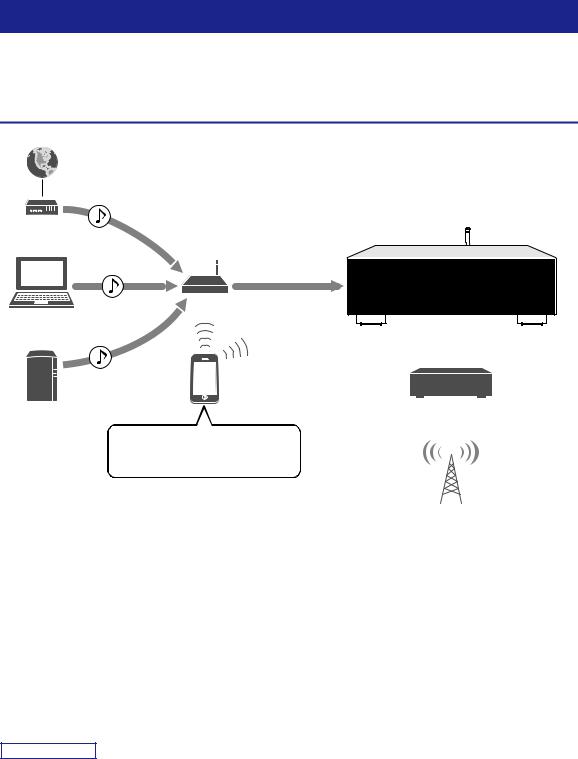
This unit is a network receiver compatible with a network source such as a media server and mobile device.
It supports playback from not only analog sources such as a CD player or AM/FM radio, but also from Bluetooth devices and network streaming services.
Sources that can be played back on this unit


 1Internet
2Streaming service
Modem
|
Router* |
3PC |
This unit |
5AirPlay (iTunes) |
|
|
Mobile |
|
device |
4NAS |
7CD player etc. |
|
|
|
5AirPlay (iPhone/iPad/iPod touch) |
|
6Bluetooth |
|
8Radio |
* You need a commercially available wireless router (access point) when you use a mobile device.
1 |
Play back the Internet radio (p. 34) |
5 |
Play back music files with AirPlay (p. 35) |
2 |
Play back the streaming service |
6 |
Play back audio content from Bluetooth |
|
(See the supplement for each service.) |
|
devices (p. 30) |
3 |
Play back music files stored on your PC (p. 32) |
7 |
Play back your external component (p. 10) |
4 |
Play back music files stored on your NAS |
8 |
Listening to radio (p. 22, 26) |
|
(p. 32) |
|
|
Note
For details on connecting the external devices, see “Connections” (p. 10).
2 En
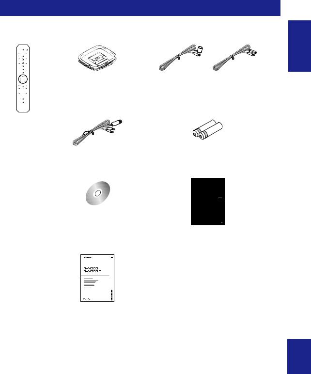
Supplied accessories
Check that the following accessories are supplied with the product.
Remote control |
AM antenna (R-N303) |
FM antenna (R-N303) |
* One of the above is supplied depending on the region of purchase.
DAB/FM antenna |
Batteries (x2) |
(R-N303D) |
(AA, R6, UM-3) |
R-N303/R-N303D Owner’s Manual |
R-N303/R-N303D Owner’s Manual |
|||||||||||||
CD-ROM (Europe model) |
(except Europe model, this book) |
|||||||||||||
|
|
|
|
Network Receiver |
||||||||||
|
|
|
|
|||||||||||
|
|
|
|
|
|
|
|
|
|
|
|
|
|
|
|
|
|
|
|
|
|
|
|
|
|
|
|
|
|
|
|
|
|
|
|
|
|
|
|
|
|
|
|
|
|
|
|
|
|
|
|
|
|
|
|
|
|
|
|
|
|
|
|
|
|
|
|
|
|
|
|
|
|
|
|
|
|
|
|
|
|
|
|
|
|
|
|
|
|
|
|
|
|
|
|
|
|
|
|
|
|
|
|
|
|
|
|
|
|
|
|
|
|
|
|
|
|
|
|
|
|
|
|
|
|
|
|
|
|
|
|
|
|
|
|
|
|
|
|
|
|
|
|
|
|
|
|
|
|
|
|
|
|
|
|
|
|
|
|
|
|
|
|
|
|
|
|
|
|
|
|
|
|
|
|
|
|
|
|
INTRODUCTION
R-N303/R-N303D Quick Start Guide
(Europe model)
Network Receiver |
Réseau Ampli-Tuner |
English
3 En
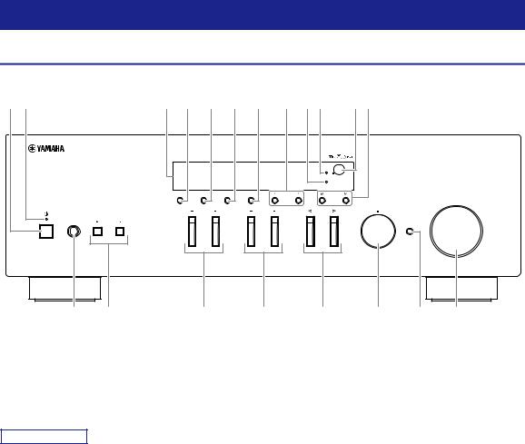
Controls and functions
Front panel
12 |
3 4 5 6 7 |
8 90 |
AB |
|
|
|
|
|
|
|
Wi Fi |
|
|
|
|
|
|
|
BLUETOOTH |
|
DISPLAY |
MODE |
MEMORY |
BAND |
PRESET |
|
TUNING |
|
|
|
|
|
|
|
VOLUME |
|
|
|
|
|
|
|
SELECT |
PHONES |
SPEAKERS |
BASS |
|
|
TREBLE |
INPUT |
PUSH ENTER |
|
|
|
|
|
|
||
|
|
|
|
|
|
|
RETURN |
|
|
|
|
|
|
|
CONNECT |
C D E F G H I J
1A (power)
Turns on/off (standby) the unit.
2STANDBY/ON indicator
Brightly lit: Power is on Dimly lit: Standby mode
Note
When not using this unit for an extended period of time, be sure to unplug it from the power outlet. This unit uses a minimal amount of power even in standby mode.
3Front display
Shows information about the operational status of this unit (p. 6).
4DISPLAY
Selects the information displayed on the front display (p. 20).
5MODE
Sets the FM band reception mode to automatic stereo or monaural (p. 22).
6MEMORY
8PRESET j / i
Recalls a preset radio station (p. 24, 22) or song/ streaming station (p. 36).
9BLUETOOTH indicator
Lights up when the unit is connecting to a Bluetooth device.
0Wi-Fi indicator
This lights when connecting to a wireless network, or when the unit is operating as an access point.
It also lights up if you register the unit with the MusicCast CONTROLLER app, even if the unit is connected to a wired network.
ARemote control sensor
Receives infrared signals from the remote control.
BTUNING jj / ii
Selects the tuning frequency (p. 22) or a DAB radio station (p. 26) when TUNER is selected as the input source.
Registers the current radio station as a preset when TUNER is selected as the input source (p. 23, 27). Registers the current playback song or streaming station as a preset when NET are selected as the input source (p. 36).
7BAND
Sets the radio tuner band when TUNER is selected as the input source. (p. 22, 26)
4 En

CPHONES jack
Outputs audio to your headphones for private listening.
DSPEAKERS A/B
Turns on or off the speaker set connected to the SPEAKERS A and/or SPEAKERS B terminals on the rear panel each time the corresponding button is pressed.
EBASS +/–
Increases or decreases the low frequency response. Control range: –10 to +10 (20 Hz)
FTREBLE +/–
Increases or decreases the high frequency response. Control range: –10 to +10 (20 kHz)
GINPUT l/ h
Selects the input source you want to listen to.
HSELECT/ENTER (jog dial)
Turn the dial to select a numeric value or setting, and press the dial to confirm.
IRETURN
Returns to the previous indication of the front display.
CONNECT
Use to control the unit using the dedicated MusicCast CONTROLLER app for mobile devices.
See MusicCast Setup Guide for details.
JVOLUME control
Increases or decreases the sound output level.
Controls and functions
INTRODUCTION
English
5 En
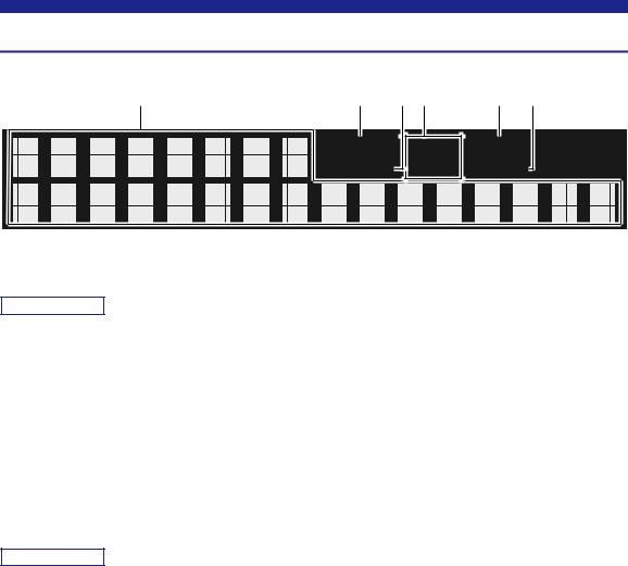
Controls and functions
Front display
1 |
2 |
3 4 |
5 |
6 |
|
STEREO SP A MUTE |
|||
|
TUNED |
SP B SLEEP |
||
Note
You can change the brightness level of the front display by pressing DIMMER (p. 8).
1Information display
Displays the current status (such as input name).
You can switch the information that is displayed when you press DISPLAY (p. 20).
2STEREO indicator
Lights up when the unit is receiving a stereo FM radio signal.
3TUNED indicator
Lights up when the unit is receiving an FM/AM radio station signal.
Note
AM radio is available only for R-N303.
4Speaker indicators
“SP A” lights up when the SPEAKERS A output is enabled and “SP B” lights up when the SPEAKERS B output is enabled.
5MUTE indicator
Blinks when audio is muted.
6SLEEP indicator
Lights up when the sleep timer is on (p. 21).
6 En
Controls and functions
Rear panel
12 |
3 |
|
|
4 |
|
|
|
5 |
SERVICE |
|
|
|
|
|
|
|
|
|
|
ANTENNA |
|
|
|
|
|
|
NETWORK |
|
FM |
|
|
|
|
|
|
|
|
AM |
|
|
|
|
|
|
|
|
75 |
|
|
|
|
|
|
|
|
|
|
SPEAKERS |
|
|
|
|
|
|
|
|
A OR B:8ΩMIN./SPEAKER |
|
|
VOLTAGE SELECTOR |
|
|
|
|
|
|
|
|
|
|
|
|
|
|
|
|
0 |
20 |
220 240 V |
DIGITAL |
|
|
|
|
|
|
|
|
OPTICAL |
PHONO |
CD |
LINE |
A |
|
|
|
|
|
GND |
|
IN |
OUT |
|
|
|
|
|
|
|
CLASS 2 WIRING |
|
|
|
|
|
COAXIAL |
|
|
|
CABLAGE CLASSE 2 |
|
|
|
|
|
|
|
|
|
|
|
|
|
|
|
|
|
B |
|
|
|
|
|
|
|
2 |
|
|
|
|
|
6 7 |
8 9 |
0 |
A |
B |
(R-N303 except Europe model) |
|||
|
|
|
||||||
INTRODUCTION
* The R-N303 Europe model and R-N303D are as shown below.
CD |
LINE |
IN OUT
2 3
9 0
1SERVICE jack
This jack is for support use, and is normally not used.
2NETWORK jack
For connecting to a network with a network cable (p. 13).
3ANTENNA terminals
For connecting to the radio antennas (p. 12).
4Wireless antenna
For connecting to a network device wirelessly (p. 13).
5Power cord
For connecting to an AC wall outlet (p. 13).
6OPTICAL jack
For connecting to audio components equipped with optical digital output (p. 10).
7COAXIAL jack
For connecting to audio components equipped with a coaxial digital output (p. 10).
8PHONO jacks (R-N303 except Europe model)
For connecting to a turntable (p. 10).
9CD jacks
For connecting to a CD player (p. 10).
0LINE 1-3 jacks (R-N303 Europe model, R-N303D)
LINE 1-2 jacks (R-N303 except Europe model)
For connecting to analog audio components (p. 10).
ASPEAKERS terminals
Used to connect speakers (p. 11).
BVOLTAGE SELECTOR (Only for General model)
English
7 En
Controls and functions
Remote control
1 |
|
|
|
|
|
|
|
|
|
|
|
|
|
|
|
|
|
|
|
|
|
|
|
|
|
|
|
|
|
||
2 |
|
|
|
|
|
|
|
|
|
|
|
|
|
|
|
|
|
|
|
|
|
|
|
|
|
|
|
|
|
||
|
|
|
|
|
|
|
|
|
|
|
|
|
|
||
3 |
|
DIMMER |
SLEEP |
|
|
|
|
|
|
||||||
4 |
|
|
|
|
|
|
|
|
|
|
|
|
|
|
|
|
|
|
|
|
|
|
|
|
|
|
|
|
|
|
|
|
|
|
|
|
|
|
|
|
|
|
|
|
|
||
5 |
|
|
|
|
A |
|
|
|
|
|
B |
|
|
||
|
|
|
|
|
|
SPEAKERS |
|
|
|
|
|
|
|||
|
|
|
|
|
|
|
|
|
|
|
|
||||
|
|
|
|
|
|
|
|
|
|
||||||
|
|
|
|
|
|
|
|
|
|
|
|
|
|
|
|
|
|
|
|
|
|
|
|
|
|
|
|
|
|
|
|
|
|
|
OPTICAL |
COAXIAL |
|
|
CD |
|
|
||||||
6 |
|
|
LINE 1 |
LINE 2 |
PHONO |
|
|
||||||||
|
|
TUNER |
NET |
BLUETOOTH |
|
|
|||||||||
|
|
|
|
||||||||||||
|
|
|
|
|
|||||||||||
|
|
|
|
|
|
|
|
|
|
|
|
|
|
|
|
|
|
|
|
|
|
|
|
|
|
|
|
|
|
|
|
|
|
|
|
|
|
|
|
|
|
|
|
|
|||
7 |
|
BAND |
|
|
TUNING |
|
|
||||||||
|
|
|
|
|
|
|
|
|
|||||||
|
|
|
|
|
|
|
|
|
|
|
|
|
|
|
|
|
|
|
|
|
|
|
|
|
|
|
|
|
|||
|
|
|
MEMORY |
|
|
|
|
|
|
|
|
|
|||
8 |
|
|
|
PRESET |
F |
||||||||||
|
|
|
|
|
|
|
|||||||||
|
|
|
|
|
|
|
|
|
|
|
|||||
|
|
|
|
|
|
|
|
|
|
|
|
|
|
|
|
|
|
|
|
|
|
|
|
|
|
|
|
|
|
|
|
9 |
CLEAR |
MODE |
DISPLAY |
|
|||
0 |
|
|
G |
|
|
|
|
A |
|
ENTER |
|
|
HOME |
|
RETURN |
B |
|
|
|
C |
SETUP |
|
OPTION |
|
VOLUME |
H |
|
|
|
|
|
|
NOW PLAYING |
|
MUTE |
D |
I |
|
J |
REPEAT |
SHUFFLE |
E
(R-N303, except Europe model)
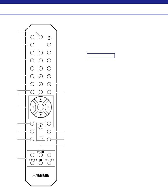
1Infrared signal transmitter
Sends infrared signals.
2A (power)
Turns on/off (standby) the unit.
3SLEEP
Sets the sleep timer (p. 21).
4DIMMER
Changes the brightness level of the front display. Choose brightness from 5 levels by pressing this key repeatedly.
5SPEAKERS A/B
Turns on and off the set of speakers connected to the SPEAKERS A and/or SPEAKERS B terminals on the rear panel of this unit when the corresponding key is pressed.
6Input selection keys
Select the input source you want to listen to.
Note
NET key is for network source. Press repeatedly to select a desired network source.
7 Radio keys
Operate the radio.
BAND Sets the radio tuner band when TUNER is selected as the input source (p. 22, 26).
TUNING jj / ii Selects the tuning frequency (p. 22) or a DAB radio station
(p. 26) when TUNER is selected as the input source.
8MEMORY
Registers the current radio station as a preset when TUNER is selected as the input source (p. 23, 27). Registers the current playback song or streaming station as a preset when NET are selected as the input source (p. 36).
9CLEAR
Deletes the preset memory (p. 24, 28, 36).
0MODE
Sets the FM band reception mode to automatic stereo or monaural (p. 22).
AMenu operation keys
Cursor keys Selects a menu, setting value or other parameter.
ENTER |
Confirms a selected item. |
RETURN |
Returns to the previous state. |
BHOME
Moves up top level when selecting music files, folders, etc.
CSETUP
Displays the “SETUP” menu (p. 39).
DNOW PLAYING
Displays music information when selecting music files, folders, etc.
8 En
EPlayback keys
Let you play back and perform other operations for network sources and Bluetooth devices.
Note
Yamaha does not guarantee the operation of all Bluetooth devices.
FPRESET j / i
Recalls a preset radio station (p. 24, 22) or song/ streaming station (p. 36).
GDISPLAY
Selects the information displayed on the front display (p. 20).
HOPTION
Displays the “OPTION” menu (p. 37).
IMUTE
Mutes the audio output.
JVOLUME +/–
Increases or decreases the sound output level.
Controls and functions
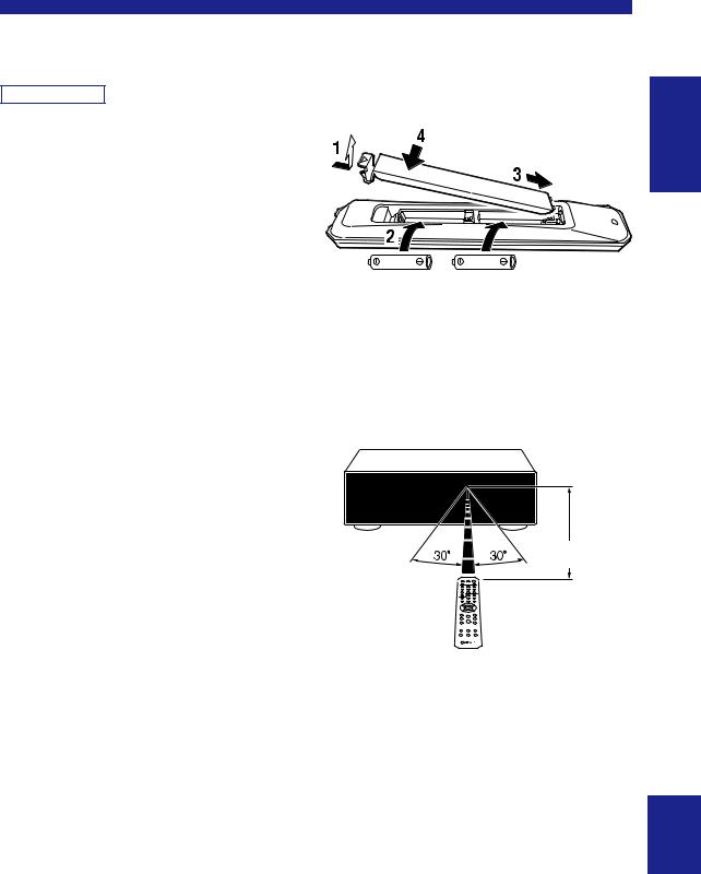
■ Installing batteries
Change all batteries if you notice the operation range of the remote control narrows. Before inserting new batteries, wipe the battery compartment clean.
AA, R6, UM-3 batteries
■ Operation range
Point the remote control at the remote control sensor on this unit and remain within the operating range shown below. The area between the remote control and this unit must be clear of large obstacles.
INTRODUCTION
Approximately 6 m (20 ft)
Remote control
English
9 En

PREPARATION
Connections
Connecting audio devices
Make sure to connect L (left) to L, R (right) to R, “+” to “+” and “–” to “–”. If the connections are faulty, no sound will be heard from the speakers, and if the polarity of the speaker connections is incorrect, the sound will be unnatural and lack bass. Refer to the owner’s manual for each of your components.
Make sure to use RCA cables to connect audio components.
 CAUTION
•Do not connect this unit or other components to the main power until all connections between components are complete.
•Do not let bare speaker wires touch each other or any metal part of this unit. This could damage this unit and/or the speakers.
CD player, etc. |
DVD player, etc. |
CD recorder, etc. |
||||||||||
|
|
|
|
|
|
|
|
|
|
|
|
|
|
|
|
|
|
|
|
|
|
|
|
|
|
|
|
|
|
|
|
|
|
|
|
|
|
|
|
|
|
|
|
|
|
|
|
|
|
|
|
|
|
|
|
|
|
|
|
|
|
|
|
|
|
|
|
|
|
|
|
|
|
|
|
|
|
Audio output C |
Audio output O |
|
Audio |
Audio |
|
|
(digital coaxial) |
(digital optical) |
|
output |
input |
(R-N303 except Europe model) |
|
|
|
|
|
|
|
|
|
|
SERVICE |
|
|
|
|
|
|
|
ANTENNA |
|
|
|
|
|
NETWORK |
FM |
|
|
|
|
|
|
AM |
|
|
|
|
|
|
75 |
|
|
|
|
|
|
|
|
|
SPEAKERS |
|
|
|
|
|
|
A OR B:8ΩMIN./SPEAKER |
|
|
DIGITAL |
|
|
|
|
|
|
OPTICAL |
CD |
LINE |
|
A |
|
|
PHONO |
|
|
||
|
|
GND |
|
IN |
OUT |
|
|
|
|
|
|
CLASS 2 WIRING |
|
|
|
COAXIAL |
|
|
|
CABLAGE CLASSE 2 |
|
|
|
|
|
|
|
|
|
|
|
|
|
B |
|
|
|
|
|
2 |
|
GND |
Audio |
|
|
|
|
|
|
output |
Audio |
|
|
|
|
|
|
|
|
|
|
|
|
|
output |
|
|
|
|
Turntable |
|
CD player |
|
|
Speakers A |
Speakers B |
Note
The input jacks are different on the R-N303 Europe model and on the R-N303D (p. 7).
Only PCM signals can be input to the digital (OPTICAL/COAXIAL) jacks of this unit.
10 En
Note
•Do not bundle audio cables and speaker cables together with the power cord. Doing so may generate noise.
•The PHONO jacks are designed for connecting a turntable with an MM cartridge.
•Connect your turntable to the GND terminal to reduce noise in the signal. However, for some turntables, you may hear less noise without the GND connection.
•On the R-N303D and R-N303 Europe models, to prevent sound loops, no sound will be outputted from the LINE 3(OUT) jack while the LINE 3 input is selected. On other models, no sound will be outputted from the LINE 2(OUT) jack while the LINE 2 input is selected.
Connecting the speakers
 CAUTION
Connect the speakers with an impedance as shown below. If you connect speakers with an excessively low impedance, this unit may overheat.
|
|
|
Speaker connection |
Speaker impedance |
|
|
|
|
SPEAKERS A or |
8 or higher |
|
SPEAKERS B |
|
|
|
|
16 or higher |
SPEAKERS A and |
||
SPEAKERS B |
(except for North America model) |
|
|
|
8 or higher |
Bi-wiring |
||
|
|
|
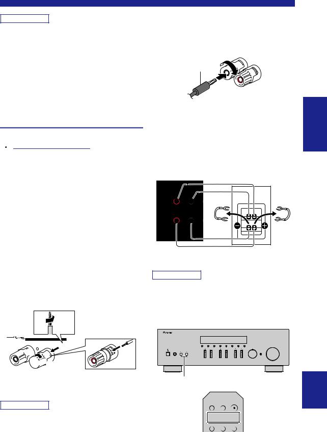
■ Connecting speaker cables
aRemove approximately 10 mm (3/8") of insulation from the ends of the speaker cable and twist the bare wires of the cable firmly together.
bLoosen the speaker terminal.
cInsert the bare wires of the cable into the gap on the side (upper right or bottom left) of the terminal.
dTighten the terminal.
a10 mm (3/8")


 c
c 

 b
b 

 d
d
Red:positive (+)
Black:negative (–)
Note
When inserting speaker cables into the speaker terminals, insert only the bare speaker wire. If insulated cable is inserted, the connection may be poor and sound may not be heard.
Connections
■Connecting via banana plug (North America, Australia,
General models only)
Tighten the knob and then insert the banana plug into the end of the corresponding terminal.
Banana plug 


■ Bi-wire connection
Bi-wire connection separates the woofer from the combined midrange and tweeter section. A bi-wire compatible speaker has four binding post terminals. These two sets of terminals allow the speaker to be split into two independent sections. With these connections, the mid and high frequency drivers are connected to one set of terminals and the low frequency driver to another set of terminals.
This unit
SPEAKER |
Speaker |
A OR B:8ΩMIN./SP |
|
A |
|
CLASS 2 WI |
|
CABLAGE CLA |
|
B
Connect the other speaker to the other set of terminals in the same way.
Note
•When making bi-wire connections, remove the shorting bridges or cables on the speaker. Refer to the speakers’ instruction manuals for more information.
•To use the bi-wire connections, press SPEAKERS A and SPEAKERS B (p. 8) so that both speaker indicators (“SP A” and “SP B”) light up on the front display.
VOLUME
SELECT
BASS |
TREBLE |
INPUT |
PHONES SPEAKERS
SPEAKERS A/B
DIMMER SLEEP
A B
SPEAKERS A/B 

 SPEAKERS

OPTICAL COAXIAL CD
PREPARATION
English
11 En
Connections
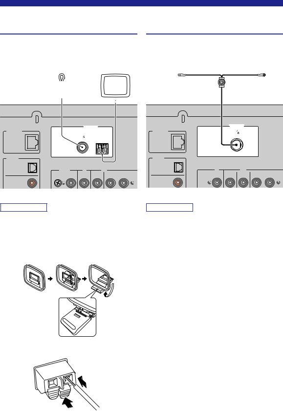
Connecting the FM/AM antennas (R-N303)
Connect the supplied FM/AM antenna to this unit.
Fix the end of the FM antenna to a wall, and place the AM antenna.
FM antenna |
AM antenna |
||||||
|
|
|
|
|
|
|
|
|
|
|
|
|
|
|
|
SERVICE
ANTENNA
NETWORK
FM
75 AM
DIGITAL
OPTICAL
PHONO |
CD |
LINE |
IN OUT
GND
COAXIAL
(except Europe model)
Note
•If you experience poor reception quality, install an outdoor antenna.
•Unwind only the length of cable needed from the AM antenna unit.
•The wires of the AM antenna have no polarity.
■ Assembling the supplied AM antenna
■ Connecting the wires of the AM antenna
2 Insert
1 Hold down
Connecting the DAB/FM antenna (R-N303D)
Connect the supplied DAB/FM antenna to this unit and fix the antenna ends to a wall.
DAB/FM antenna
SERVICE |
|
|
|
ANTENNA |
|
NETWORK |
DAB FM |
|
|
75 |
|
DIGITAL |
|
|
OPTICAL |
|
|
CD |
LINE |
|
|
IN |
OUT |
COAXIAL |
|
|
Note
•If you experience poor reception quality, install an outdoor antenna.
•The antenna should be stretched out horizontally.
12 En
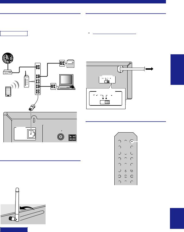
Connecting the network cable
Connect the unit to your router with a commerciallyavailable STP network cable (CAT-5 or higher straight cable).
Note
Use STP (Shielded Twisted Pair) cable to prevent electromagnetic interference.
Internet |
Network Attached |
|
Storage |
|
(NAS) |
|
WAN |
LAN
Modem
Router |
PC |
|
|
||
Mobile device |
Network cable |
|
(such as iPhone) |
||
|
SERVICE |
|
ANTENNA |
|
NETWORK |
|
FM |
AM |
75 |
This unit (rear) |
(R-N303) |
Preparing a wireless antenna
If you connect the unit wirelessly, erect the wireless antenna. For information on how to connect the unit to a wireless network, see “Connecting to network” (p. 14). For more information on using this unit with a Bluetooth device, see “Playing back music via Bluetooth” (p. 30).
Notice
Do not apply excessive force on the wireless antenna. Doing so may damage the antenna.
Connections
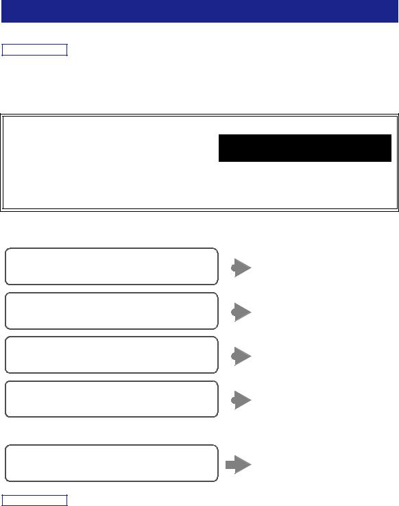
Connecting power cord
Plug the power cord into an AC wall outlet after all other connections are complete.
 WARNING
Only for General model:
Before connecting the power cord, make sure you set VOLTAGE SELECTOR of this unit according to your local voltage. Improper setting of VOLTAGE SELECTOR may cause fire and damage to this unit.
|
|
MAINS |
To the AC wall outlet |
PREPARATION |
|
|
|
||
|
VOLTAGE SELECTOR |
|
with the power cord |
|
0 |
20 220 240 V |
|
|
|
VOLTAGE SELECTOR |
|
|
|
|
0 20 |
220 240 V |
|
|
|
Turning on the unit
Press A(power) to turn on the unit.
DIMMER |
SLEEP |
|
|
|
|
|
A (power) |
||
|
|
|
|
|
|
|
|
|
|
|
|
|
|
|
|
|
|
|
|
A |
|
|
|
|
B |
||||
|
|
SPEAKERS |
|
|
|
|
|
|
|
|
|
|
|
|
|
|
|
|
|
OPTICAL |
COAXIAL |
|
|
CD |
|||||
LINE 1 |
LINE 2 |
PHONO |
|||||||
TUNER |
NET |
BLUETOOTH |
|||||||
|
|
|
|
|
|
|
|
|
|
BAND |
|
TUNING |
|||||||
|
|
|
|||||||
MEMORY |
|
|
|
|
|
|
|
|
|
|
PRESET |
||||||||
|
|
|
|||||||
|
|
|
|
|
|
|
|
|
|
CLEAR |
MODE |
|
DISPLAY |
||||||
English
13 En
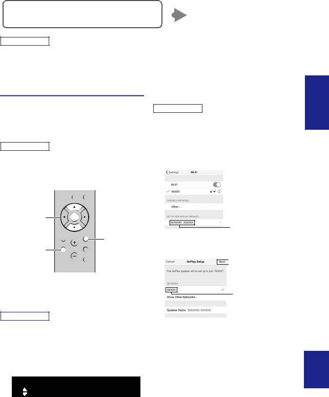
Connecting to a network
There are several methods to connect the unit to a network. Select a connection method according to your environment.
Note
•Some security software installed on your PC or the firewall settings of network devices (such as a router) may block the access of the unit to the network devices or the Internet. In these cases, configure the security software or firewall settings appropriately.
•Each server must be connected to the same subnet as the unit.
•To use the service via the Internet, broadband connection is strongly recommended.
•When playing a high-resolution audio source via the network, we recommend connecting by cable to the router for stable playback.
WAC (Wireless Accessory Configuration)
If you turn on the power to the unit right after you purchase or initialize it, the unit will automatically use the network settings of the iOS device (iPhone/iPad/iPod touch) and try to connect to a wireless LAN (unless the unit is already connected to a wired LAN).
WAC
R-N303 XXXXXX
R-N303 (example)
If you have an iOS device, follow the procedure from Step 6 in the section “Sharing the iOS device setting” (p. 15).
If you plan to connect the unit wirelessly by another method, press RETURN to exit the current screen, and then proceed to one of the sections below.
■ Connecting with a wireless router (access point)
Connect to the network with the method listed below that corresponds to your environment.
Connecting with the MusicCast CONTROLLER |
|
See “Configuring MusicCast” |
|
app |
|
|
(p. 19) for details. |
|
|||
|
|
||
Connecting using the Wi-Fi setting of the iOS |
|
Share the Wi-Fi setting of the iOS |
|
device (iPhone / iPad / iPod touch) |
|
|
device (p. 15) |
|
|||
|
|
||
Connecting using WPS push button configuration |
|
Use the WPS push button |
|
on the wireless router (or access point) |
|
|
configuration (p. 16) |
|
|||
|
|
||
Connecting with a wireless router (access point) |
|
Set the network connection |
|
without WPS push button configuration |
|
|
manually (p. 16) |
|
|||
|
|
||
■ Connecting to a router using a cable
Connecting using the DHCP server function of the router
Note
You can connect to the network by simply making a wired connection (p. 13)
•For information on how to set the IP address and other menu items, please refer to page 40.
•To switch from a wireless LAN connection to a wired LAN connection, set the “Connection” under the “Network” setup menu to “Wired” (p. 40).
14 En
|
|
|
Connecting to a network |
■ Connecting without a wired router or wireless router (access point) |
|||
Connecting wirelessly to a mobile device |
|
Connect wirelessly with Wireless |
|
(Wireless Direct) |
|
|
Direct (p. 17) |
|
|||
|
|
||
Note
When the unit is connected to the network with Wireless Direct, it cannot connect to any other wireless router (access point). To play back contents from the Internet or to update the firmware of this unit over the network, connect the unit to a network with a wired router or wireless router (access point).
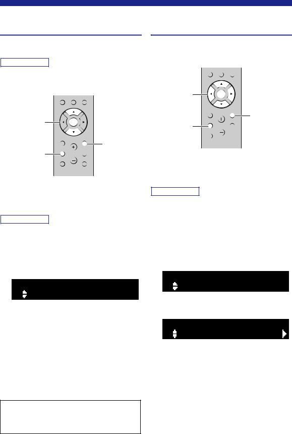
Sharing the iOS device setting
You can easily setup a wireless connection by applying the connection settings on iOS devices (iPhone/iPad/iPod touch).
Before proceeding, confirm that your iOS device is connected to a wireless router (access point).
Note
•If you perform the following procedure, all network settings will be initialized.
•This configuration does not work if the security protocol of your wireless router (access point) is WEP. In this case, use another connection method.
CLEAR MODE DISPLAY
Cursor keys / |
ENTER |
ENTER |
|
HOME |
RETURN |
|
RETURN |
SETUP |
OPTION |
SETUP |
VOLUME |
NOW PLAYING |
MUTE |
1Press SETUP.
2Use the cursor keys ( / ) to select
“Network” and press ENTER.
Note
To return to the previous state, press RETURN.
3Use the cursor keys ( / ) to select
“Connection” and press ENTER.
4Use the cursor keys ( / ) to select
“Wireless” and press ENTER.
5Use the cursor keys ( / ) to select “Share
Setting” and then press ENTER twice.
Note
When connected to a wired network, the front display will show the messages “LAN CBL” and “Pls disconnect”. Unplug the network cable from the unit, and press the ENTER key.
6On the iOS device, select the unit as the AirPlay speaker in the Wi-Fi screen.
Example (iOS 10)
The name of this unit
7Check that the “Network” field is set to your preferred network, and then tap “Next”.
 Tap here to start setup
The network currently selected
When the sharing process finishes, the unit is automatically connected to the selected network (access point).
When the setting finishes, verify whether the unit is connected to a wireless network (p. 18).
WIRELESS ¡WPS
PREPARATION
English
15 En
Connecting to a network
Configuring with the router’s WPS push button
You can easily set up a wireless connection with one push of the WPS button.
Note
This configuration does not work if the security method of your wireless router (access point) is WEP or WPA2-TKIP. In this case, use another connection method.
CLEAR MODE DISPLAY
Cursor keys / |
ENTER |
ENTER |
|
HOME |
RETURN |
|
RETURN |
SETUP |
OPTION |
SETUP |
VOLUME |
NOW PLAYING |
MUTE |
1Press SETUP.
2Use the cursor keys ( / ) to select
“Network” and press ENTER.
Note
To return to the previous state, press RETURN.
3Use the cursor keys ( / ) to select
“Connection” and press ENTER.
4Use the cursor keys ( / ) to select
“Wireless” and press ENTER.
WIRELESS ¡WPS
5Press ENTER twice.
“Connecting” appears on the front display.
6Push the WPS button on the wireless router
(access point).
When the connection process finishes, “Completed” appears on the front display. When the setting finishes, verify whether the unit is connected to a wireless network (p. 18).
If “Completed” does not appear, repeat from Step 1 or try another connection method.
7To exit from the menu, press SETUP.
About WPS
WPS (Wi-Fi Protected Setup) is a standard established by the Wi-Fi Alliance, which allows easy establishment of a wireless home network.
Set the wireless network connection manually
Before performing the following procedure, check the security method and security key on the wireless router (access point).
CLEAR MODE DISPLAY
Cursor keys |
ENTER |
ENTER |
|
HOME |
RETURN |
|
RETURN |
SETUP |
OPTION |
SETUP |
VOLUME |
NOW PLAYING |
MUTE |
1Press SETUP.
2Use the cursor keys ( / ) to select
“Network” and press ENTER.
Note
To return to the previous state, press RETURN.
3Use the cursor keys ( / ) to select
“Connection” and press ENTER.
4Use the cursor keys ( / ) to select
“Wireless” and press ENTER.
5Use the cursor keys ( / ) to select
“ManualSetting” and press ENTER.
MANUAL ¡SSID
6Use the cursor keys ( / ) to select “SSID” and press ENTER.
SSID
¡


16 En
Loading...